X-SENSORS FC 10 User manual

Measuringsystem
Measuringrange[Max]: 1kN
Overloadprotection(of[Max]): 150%
Precision(of[Max]): 0,002
Readout[d]: 1N
Testfrequency: 1000Hz
Display
Displaydigitheight: 1cm
Functions
Dataholdfunction: yes
Displayrevolving: yes
Functiontoset limits: yes
Peakfunction: yes
Visualreadysignal: yes
Environmentalconditions
Maximumoperatingtemperature: 40OC
Minimumambienttemperature: -10OC
Powersupply
Chargingtime: 4h
Inputvoltage: 100V-240V
n/a: CHEURO
Powersupply
Operatingtime(Backlightoff): 20h
Service
DAkkSCalibrationcertificate 963-262
(Pressure):
DAkkSCalibrationcertificate 963-162
(Tensile):
DAkkSCalibrationcertificate 963-362
(Tensile/Pressure):
ISOCalibrationcertificate(Tensile): 961-162
Category
Category: Forcegauges
ProductGroup: Electronicforce-measuring
device
Packaging&shipping
Delivery: 24h
Dimensionspackaging(WxDxH): 340x155x110mm
Grossweight: 1,200kg
Netweight: 940g
Shippingmethod: Parcelservice
UN number: 3496
Construction
Casingmaterial: metal
Dimensionsofdisplaydevice 145x73x34mm
(WxDxH):
X-SENSORS GmbH l Steinbrechstr. 9, 71106 –Magstadt, Deutschland l Tel: +49 7159/49697-0 l info@sensorshop.com l www.sensorshop.com
FC X-SENSORS GmbH
Magstadt, Deutschland l Tel: +49 7159/49697-0
info@sensorshop.com l www.sensorshop.com Kompetenz in Messtechnik und Kundenbetreuung

STANDARD OPTION
Model
Measuring range
[Max
] N
Readout
[d
]
N
Option ISOCalibration Certificate
Tension Compression Tension/Compression
FC
10 10 0,01 961-161 961-261 961-361
FC
50 50 0,01 961-161 961-261 961-361
FC
100 100 0,1 961-161 961-261 961-361
FC
500 500 0,1 961-161 961-261 961-361
FC
1K 1000 1 961-162 ––
Digital force gauge FC
Compact force measuring device
Features
•Turnable displaywith backlight
•Peak-Holdfunctionto capture peaks
(measure-
mentresult willbe “frozen” for a short time) or
Trackfunctionmode for acontinuous measure-
mentindication (period of timeapprox. 10s)
•Metal housingfor durable usage in harsh
environmentalconditions
•Capacity display:A bar lights up to show
how much of the measuring range is still
available
•Function tosetlimits, programming of
Max./Min., in pull and push direction,with
output of acoustic and optical signal. Ideal
mode for efficientand accurate testing of
standardparts
•Safety: If loads exceed 110 % of the measuring
range, the device will give clear acoustic and
visualsignals
•Internalmemoryfor up to 1000 measurements
•Data interfaceRS-232
(only for connection to the printer)
•Selectable: AUTO-OFF function or permanent
operation
•Delivered in a hard carrying case
•Selectable measuring units: N, kg, oz, lb
•Standard attachments:asshown below
•Can be mounted on all teststands (with
adapterplate)
Technical data
•Precision: 0,2 % of
[Max]
•Internal measuring frequency: 1000 Hz
•Overload protection: 150 % of
[Max]
•Overall dimensions WxDxH 145x73x34mm
•Thread:M6
•Net weight approx. 940 g
•Permissible ambienttemperature
-10 °C/40°C
Accessories
•Force-timedatatransfersoftwarefor
graphical representation on the PC and data
transfer to Microsoft Excel,
AFHFAST
•Force-displacementdatatransfersoftware
with graphic display of the measurement
process, AFHFD
•Standard attachments,
AC 43
•Further accessory see
www.SensorShop.com
X-SENSORS GmbH l Steinbrechstr. 9, 71106 –Magstadt, Deutschland l Tel: +49 7159/49697-0 l info@sensorshop.com l www.sensorshop.com
FC X-SENSORS GmbH
Magstadt, Deutschland l Tel: +49 7159/49697-0
info@sensorshop.com l www.sensorshop.com Kompetenz in Messtechnik und Kundenbetreuung

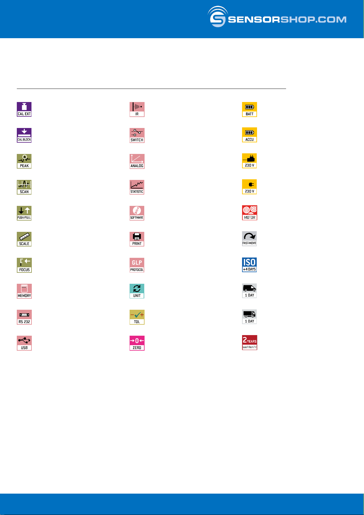
Adjusting program (CAL):
For quick setting of the balance’s accuracy.
External adjusting weight required.
Calibration block:
standard for adjusting or correcting
the measuring device.
Peakhold function:
capturing a peak value within a
measuringprocess.
Scanmode:
continuous capture and display
of measurements.
PushandPull:
the measuring device can capture tension
and compression forces.
Lengthmeasurement:
captures the geometric dimensions of
a test object or the movement during
a test process.
Focus function:
increases the measuring accuracy of a
device within a defined measuring range.
Internal memory:
to save measurements
in the device memory.
Data interface RS-232:
bidirectional, for connection
of printer and PC.
Data interface USB:
Toconnect the balance to a printer,
PC or other peripheral devices.
Datainterface Infrared:
Totransfer data from the balance to a
printer, PC or other peripheral devices.
Controloutputs
(optocoupler, digital I/O):
to connect relays, signal lamps, valves, etc.
Analogue interface:
to connect a suitable peripheral device for
analogue processing of the measurements.
Statistics:
using the saved values, the device
calculates statistical data, such as
average value,standard deviation etc.
PC Software:
to transfer the measurements from
the device to a PC.
Printer:
a printer can be connected to the
device to print out the measurements.
GLP/ISO recordkeeping:
of measurements with date, time and
serial number. Only with printers.
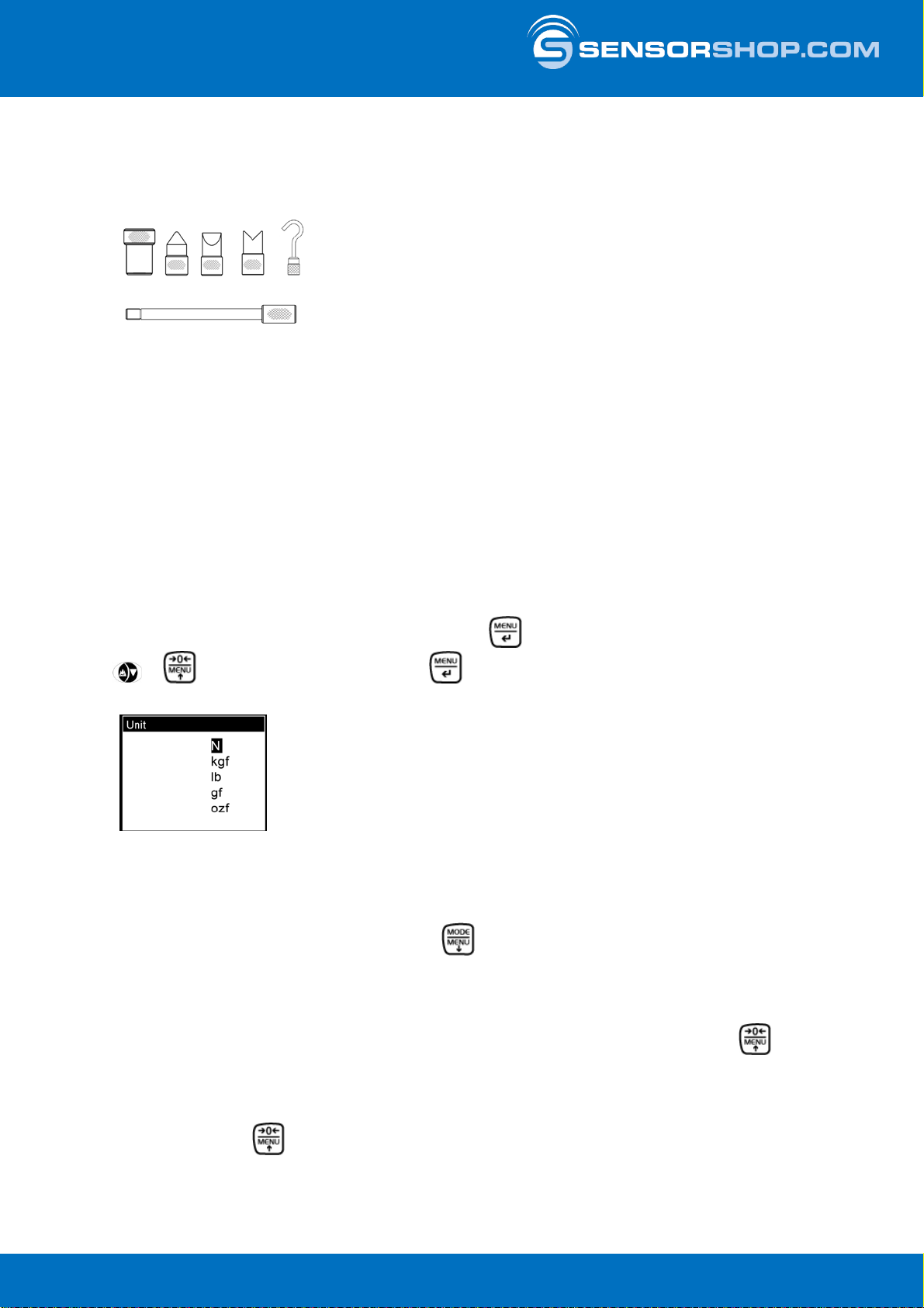
Measuringunits:
Weighing units can be switched to
e.g. non-metric at the touch of a key.
Please refer to website for more details.
Measuring with tolerance range:
Upper and lower limiting can
be programmed individually,
e.g. for sorting and dosing.
ZERO:
Resets the display to “0”.
Batteryoperation:
Ready for battery operation.
The battery type is specified
for each device.
Rechargeable battery pack:
rechargeable set.
Mainsadapter:
230V/50Hz in standard version for EU.
On request GB, AUS or USA version
available.
Powersupply:
Integrated, 230V/50Hz in EU.
More standards e.g. GB, AUS
or USA onrequest.
Motoriseddrive:
The mechanical movement is carried out
by a motorised drive.
Fast-Move:
the total length of travel can be covered
by a single lever movement.
ISO Calibration:
The time required for ISO calibration
is shown in days in the pictogram.
Packageshipment:
The time required for internal
shipping preparations is shown
in days in the pictogram.
Palletshipment:
The time required for internal
shipping preparations is shown
in days in the pictogram.
Warranty:
The warranty period is shown
in the pictogram.
Pictograms:
X-SENSORS GmbH l Steinbrechstr.9, 71106 –Magstadt, Deutschland l Tel: +49 7159/49697-0 l info@sensorshop.coml www.sensorshop.com
FC X-SENSORS GmbH
Magstadt, Deutschland l Tel: +49 7159/49697-0
info@sensorshop.com l www.sensorshop.com Kompetenz in Messtechnik und Kundenbetreuung

FC-BA-e-1410
Instruction
Manual
Digital Force
Gauge
FC
Version
1.0
02/2014
GB
X-SENSORS GmbH l Steinbrechstr.9, 71106 –Magstadt, Deutschland l Tel: +49 7159/49697-0 l info@sensorshop.coml www.sensorshop.com
FC X-SENSORS GmbH
Magstadt, Deutschland l Tel: +49 7159/49697-0
info@sensorshop.com l www.sensorshop.com Kompetenz in Messtechnik und Kundenbetreuung

2 FC-BA-e-1410
GB FC
Version 1.0 01/2014
Instruction Manual Digital Force gauge
Summarize
1General Specifications 4
1. Overview 4
2. LCD Screen 4
3. Key Functions 5
4. Specifications 5
2 Operation 5
1. Preparation 5
2. Testing 6
3. Save the measured value 7
4. Browse and printdata 7
3 Setup 7
1. Setup menu 7
2. Measurement 8
3. Memory 8
1. Browse 8
2. Print 9
3. Delete All 10
4. System 10
1. Display 10
2. AutoPower 11
3. Backlight 11
4. Key Sound 11
5. Date/time 11
6. Calibration 12
7. Default 12
5. Language 12
6. Info 12
4 Communication Port 12
1. USB/Recharge 12
2. Multifunction port 13
4.2.1 RS-232 13
4.2.2 Setpoint Output 13
5 Maintenance and Calibration 14
1. Maintenance 14
2. Charging 14
3. Calibration 14
4. Troubleshooting 15
6 Declaration of Conformity 18
X-SENSORS GmbH l Steinbrechstr.9, 71106 –Magstadt, Deutschland l Tel: +49 7159/49697-0 l info@sensorshop.coml www.sensorshop.com
FC X-SENSORS GmbH
Magstadt, Deutschland l Tel: +49 7159/49697-0
info@sensorshop.com l www.sensorshop.com Kompetenz in Messtechnik und Kundenbetreuung

FC-BA-e-1410 3
NOTICE
Please carefully read this first
1.During the test, please wear protective masks and gloves, because splashes
could injure your body.
2. DO NOT exceed the capacity of the gauge.At 110% of the capacity, the display
flashes and the alarm sounds; please remove the load immediately.
If 150% of the rated capacity is exceeded, the load cell may be damaged forever.
3. When mounting measurement adapters, tighten them by hand, DO NOT use tools.
4. FC series force gauge can only measure and bear axial forces, radial
forces are too large and would damage the instrument.
5. Do not disassemble the gauge by yourself, it may damage the instrument.
6. Please use and store it in a suitableenvironment, as not to reducethe service
life or causefailure.
7. To avoid injury, do not point the light beam of the instrument or let it reflect into the
eyes of people or animals.
8. Do not leave the deviceclose to water or any other liquid, to avoid damage.
9. If the instrument isn’t used for an extended periodof time, batteries have to be
removed. They have to be recharged every 2-3 months to prevent a potential
battery leakage and causing any product damage.
X-SENSORS GmbH l Steinbrechstr.9, 71106 –Magstadt, Deutschland l Tel: +49 7159/49697-0 l info@sensorshop.coml www.sensorshop.com
FC X-SENSORS GmbH
Magstadt, Deutschland l Tel: +49 7159/49697-0
info@sensorshop.com l www.sensorshop.com Kompetenz in Messtechnik und Kundenbetreuung

4 FC-BA-e-1410
1 General Specifications
1.1 Overview
flashesifthe
①Test mode icon:
:Track, :Peak, :Preset
②Battery icon: Indicating the battery level or charging status,
gauge needs to berecharged
:
③Preset Mode Test status mark :
The measured valuebetween the upper limit and lower limit that is OK; The
measured value between the lowerlimit and 75% of the lower limit,
which means it is below the lower limit
Fig1-1
1.2 LCDScreen
Fig1-2
X-SENSORS GmbH l Steinbrechstr.9, 71106 –Magstadt, Deutschland l Tel: +49 7159/49697-0 l info@sensorshop.coml www.sensorshop.com
FC X-SENSORS GmbH
Magstadt, Deutschland l Tel: +49 7159/49697-0
info@sensorshop.com l www.sensorshop.com Kompetenz in Messtechnik und Kundenbetreuung

FC-BA-e-1410 5
: The measured valuehigherthan the upper limit
④Test units: Displays selectedmeasuring unit (N, kgf, ozf, and lbf selectable)
⑤System time
⑥Data transmission icon
⑦Data storage icon
⑧Analogue bar
⑨Current measured value
⑩Force direction Indicator -
- for tension:
forcompression:
1.3 KeyFunctions
Power: ON/OFF Storage / Back
Zero/Up Menu/Enter
Test Mode/Down
1.4 Specifications
2Operation
2.1 Preparation
Confirm the model
This series force gauge has 5 models which can be selected, each model corre-
sponding to the capacity and resolution, shown in a table on the last page of this
manual. Select the appropriate model you needbefore use.
Accuracy
±
0.3%F.S.
Units
N,
kgf, ozf, and lbf.(Selectable)
Display
160*128matrix LCD with
Backlight
Overload
Capacity
150% of max. (LCD flashes beyond 110%
of
max.)
Measurement
mode
Track
,Peak andPreset
Data Sampling
Rate
1000
Hz
Memory
500
data
Set
Point
Programmable high and low
limits
Power
3.6VDC 450mAH Ni
-MH rechargea-
ble
batteries
Charger
/ Adaptor
USB/BM charger,
Input:110~240VAC
Temperature
Effects
<0.03% of
max per°C
Dimensions
140x 71.2x
35.5
mm
Weight
0.4 kg
(0.9lb)
X-SENSORS GmbH l Steinbrechstr.9, 71106 –Magstadt, Deutschland l Tel: +49 7159/49697-0 l info@sensorshop.coml www.sensorshop.com
FC X-SENSORS GmbH
Magstadt, Deutschland l Tel: +49 7159/49697-0
info@sensorshop.com l www.sensorshop.com Kompetenz in Messtechnik und Kundenbetreuung

6 FC-BA-e-1410
Choose the adapter
In order to complete the test work convenient, the standard force gauge is equipped
with a variety of measuring heads. According to the actual need, please select the
appropriatemeasurement adapter, shown in Fig 2-1:
2.2 Testing
After completingthe test preparation,testing can be performed.
①How to mount the measuring adapter:Install the adapterin the gauge's
measurement shaft. Tighten it by hand, not by any tools.
NOTE: Do not use tools for tighten the adapter; otherwise it will damage the
forcegauge.
②Select the appropriate units. A variety of measurement units can be chosen.
In the measure interface,press the Menu key to enter the menu interface, press
or select Measurement, press to enter, and then select Unit to enter.
Choose the unit you desired here.
can change the Test Modes one to an-
Under the measure interface, just press
other.
You can also set it in Menu, see §3.2.
and
Track: The real time measuring mode. Under this mode, press the zero key
you can remove the tare force.
Peak: In Peak mode, the maximum of force will be measured and displayed.Under
this mode, press and the force gauge will update the display immediately.
Flat Conical Chisel Notched Hook
Extension rod Fig2-1
Fig2-2
③Select the appropriate Test Mode.
This series has 3 kinds of test modes; select your appropriate test mode for meas-
urement.
X-SENSORS GmbH l Steinbrechstr.9, 71106 –Magstadt, Deutschland l Tel: +49 7159/49697-0 l info@sensorshop.coml www.sensorshop.com
FC X-SENSORS GmbH
Magstadt, Deutschland l Tel: +49 7159/49697-0
info@sensorshop.com l www.sensorshop.com Kompetenz in Messtechnik und Kundenbetreuung

FC-BA-e-1410 7
Under menu interface:Press or
The setting will be very simple:
Under measure interface:Press Menu
key can enter Menusetup.
can select the item of menu.
Press
Press will confirm a setup and return.
can cancel some settingand return or just for return.
Preset: In this mode, you can set the toleranceupper limit and lower limit of meas-
ured force value to do a GO/NG measurement. See chapter 3.2.
④Before measurement, you should zero the tare by pressing .
⑤The force gauge often is used hand-held. But mounting it on a test stand for use
may be more accurate and easier or safer. We just recommend this way of use.
3. Save the measured value
Measured results can be stored in the force gauge; you can review or print them
later.
Duringthe measurement, press the key to store a value, and the storage Icon
will be displayed.
The data stored is the one displayedcurrently. So, in Track and Preset mode it is the
current force value measured, in Peak mode it is the peak value.
4. Browse and print data
All data stored in the memory can be browsed or printedby the mini-printer.
See chapter3.3.1 and 3.3.2 for details.
3 Setup
3.1 Setup menu
This series force gauge has multi-level menu interface. Show as Table 3-1.
Table3-1
Menu
Measurement
Unit
TestMode
Memory Browse
Print
DeleteAll
System
Display
AutoPo-
wer
Backlight
Key
Sound
Date/Time
Calibration
Default
Language
Info
X-SENSORS GmbH l Steinbrechstr.9, 71106 –Magstadt, Deutschland l Tel: +49 7159/49697-0 l info@sensorshop.coml www.sensorshop.com
FC X-SENSORS GmbH
Magstadt, Deutschland l Tel: +49 7159/49697-0
info@sensorshop.com l www.sensorshop.com Kompetenz in Messtechnik und Kundenbetreuung

8 FC-BA-e-1410
3.2 Measurement
Measurement item contains the unit of measurement and measurement mode,
In Unit, N, kgf, ibf, ozf can be selected, as shown in Fig 3-1.
In Test Mode Track, Peak, Preset etc. can be chosen (see Fig 3-2, or see §2.2 also)
If Preset is selected, the Upper limit and Lower limit can be set.
Press to adjust the number and press to move the nextdigit.
3.3 Memory
Memory item contains three submenus: Browse, Print, Delete all, shown in Fig 3-3.
You can browse or print (wireless mini-printer), and delete some (in browse) or all
data inmemory.
3.3.1 Browse
Enter Browse, the data in memory can be reviewedin the order saved.
Press or to move andselect.
Maximum number of data is the one obtained recently.
Press and a small window will pop off. Here you can select Delete or Print.
SeeFig.3-4.
Fig3-1
Fig3-3
Fig3-2
X-SENSORS GmbH l Steinbrechstr.9, 71106 –Magstadt, Deutschland l Tel: +49 7159/49697-0 l info@sensorshop.coml www.sensorshop.com
FC X-SENSORS GmbH
Magstadt, Deutschland l Tel: +49 7159/49697-0
info@sensorshop.com l www.sensorshop.com Kompetenz in Messtechnik und Kundenbetreuung

FC-BA-e-1410 9
If you select Delete, a confirm window will appear to ask you confirm.
Or press to exit.
Fig3-5
3.3.2 Print
You can printthe data in memory with mini-printer;see (Fig 3-5)
Enter Print, select Selected orAll.
If Selected is chosen, enter the range of number will be needed.
If All is selected, a confirm window will appear to ask you confirm.
See Fig3-6
→
→
Fig3-6
X-SENSORS GmbH l Steinbrechstr.9, 71106 –Magstadt, Deutschland l Tel: +49 7159/49697-0 l info@sensorshop.coml www.sensorshop.com
FC X-SENSORS GmbH
Magstadt, Deutschland l Tel: +49 7159/49697-0
info@sensorshop.com l www.sensorshop.com Kompetenz in Messtechnik und Kundenbetreuung

10 FC-BA-e-1410
3.3.3 Delete All
All data can be deleted at one time to empty the memory (Fig 3-7).A confirm window
will appearto ask you confirm.
Deletionof an individual data can be done in Browse, see chapter 3.3.1.
3.4 System
Under system settings menu, the display, auto power, backlight, key sound and so
on can be set. Fig. 3-8
3.4.1 Display
There are two display modes: Obverse, Reverse, show as Figure 3-7.According to
actual needs, select the appropriate displaymode, shown in Fig 3-9
Fig3-7
Fig3-9
Obverse Reverse
Fig3-8
X-SENSORS GmbH l Steinbrechstr.9, 71106 –Magstadt, Deutschland l Tel: +49 7159/49697-0 l info@sensorshop.coml www.sensorshop.com
FC X-SENSORS GmbH
Magstadt, Deutschland l Tel: +49 7159/49697-0
info@sensorshop.com l www.sensorshop.com Kompetenz in Messtechnik und Kundenbetreuung

FC-BA-e-1410 11
3.4.2 Auto Power.
This series force gauge has an automatic power off function.
Turn on the Auto power, if any operation isn’t performed within five minutes, it will
power off automatically, shown in Fig 3-10:
3.4.3 Backlight.
The backlightcan be set to turn on or off, show in Fig 3-11. Without backlight the
consumption of battery will be reduced.
Fig.3-11:
3.4.4 Key Sound
Key sound can be turned on or off by this setting, shown in Fig 3-12.
Fig.3-12:
3.4.5 Date/time
System date and time can be adjusted under this menu.
Press to adjust the number and press to move the nextdigit.
Shown in Fig 3-13:
X-SENSORS GmbH l Steinbrechstr.9, 71106 –Magstadt, Deutschland l Tel: +49 7159/49697-0 l info@sensorshop.coml www.sensorshop.com
FC X-SENSORS GmbH
Magstadt, Deutschland l Tel: +49 7159/49697-0
info@sensorshop.com l www.sensorshop.com Kompetenz in Messtechnik und Kundenbetreuung

6. Calibration
For details, see chapter 5.3.
7. Default
With this function,the force gauge can be restored back to the factory settings. This
function should be performed under the guidanceof professionals usually.
5. Language
The force gauge can display in multi-language,set the language desired.
See Fig3-14:
3.6 Info
Here you can find out some informationabout the force gauge, such as model, ver-
sion and serialnumber.
See Fig.3-15:
Fig.3-15
4 Communication Port
The force gauge has two kinds of ports for rechargingand communicating with PC
and otherequipment.
4.1 USB/Recharge
Using this port, you can connect the gauge to the computer for transform data to PC
in accordancewith USB2.0.
12 FC-BA-e-1410
X-SENSORS GmbH l Steinbrechstr.9, 71106 –Magstadt, Deutschland l Tel: +49 7159/49697-0 l info@sensorshop.coml www.sensorshop.com
FC X-SENSORS GmbH
Magstadt, Deutschland l Tel: +49 7159/49697-0
info@sensorshop.com l www.sensorshop.com Kompetenz in Messtechnik und Kundenbetreuung

FC-BA-e-1410 13
Or rechargethe internal Ni-MH battery by connecting the recharger.
USB/
Recharge Multifunction
Port
4.2.1 RS-232
The RS232 serial port is only used to connect the mini-printerto print the memory
data.
RS-232specifications:
-Hardware Flow Control: None
-Data word length:
-Stop bit:
-Parity:
-Baud rate:
8 bits
1 bit
None
38400
4.2.2 Setpoint Output
Two setpointoutputs are NPN open collector.
The internal circuit of setpoint output is shown
Fig4-1
4.2 Multifunction port
The assignmentof pins is shown in Table 4-1
Table4-1 Pin Assignment
Pin#
Description
1
RS232
Tx
2
Rx
3
Gnd
4
SetpointOutput
B
5
6
SetpointOutput
C
(Common)
7
SetpointOutput
A
8
X-SENSORS GmbH l Steinbrechstr.9, 71106 –Magstadt, Deutschland l Tel: +49 7159/49697-0 l info@sensorshop.coml www.sensorshop.com
FC X-SENSORS GmbH
Magstadt, Deutschland l Tel: +49 7159/49697-0
info@sensorshop.com l www.sensorshop.com Kompetenz in Messtechnik und Kundenbetreuung

14 FC-BA-e-1410
Fig4-2
Pin7 with Pin6 willbe connected when an overloadalarm occurs.
In Preset Mode, Pin7 to Pin6 is connectedwhen the measured valueexceeds the
upper limit; Pin4 to Pin6 is connectedwhen the measured value is below the lower
limit.
! Maximum permissible voltage: pin 7 to 6, pin 4 to 6 must be lower than 35V ;
pin 6 to 7, pin 6 to 4 must be lower than 6V .
5 Maintenance and Calibration
1. Maintenance
After use, pleasekeep the instrument body clean, do not let oil or other substances
infiltrateinto the body and the screen, not to damage the instrument.
Please do not forget to remove the load after measurement.Applyinga load for a
long time may affect the accuracy of the instrument.
Unless there is a special need, please do not switch off the Auto Power, because it
can reduce the consumption of the battery and extend batteries life.
2. Charging
When the batteries are low, the icon “” will be displayed. The batteries should be
charged immediately.
Connect the gauge and the charger using the USB cable, and then connect the
charger with AC socket to start charging.
It takes about 3~4 hours for completely charging.
3. Calibration
Because of the sensor’s material performance or the influence of external factors,
there may be errors in a certainrange after being used a period of times.
The force gauge can be sent to us for a specialized testing and for calibration.
If you have some standardforce weights or the other standardload and some test
stand, you may calibrate it also on your own, as shown below:
❶Mount the force gauge to a test stand or fix it anywhere else
❷Remove the tare by using the key .
X-SENSORS GmbH l Steinbrechstr.9, 71106 –Magstadt, Deutschland l Tel: +49 7159/49697-0 l info@sensorshop.coml www.sensorshop.com
FC X-SENSORS GmbH
Magstadt, Deutschland l Tel: +49 7159/49697-0
info@sensorshop.com l www.sensorshop.com Kompetenz in Messtechnik und Kundenbetreuung

FC-BA-e-1410 15
❸Enter Calibrationinterface, as shown in Fig 5-1.
Fig.5-3
(a) (b)
Calibrationinterfaceis shown in
Fig5-2
(c) (d)
❹Load a standardforce. Now the value in standard inputarea is just equal to the
current measured value. Wait a moment for the force stabilization.
❺Press and to input the standard force value.
❻Press to enter the next calibration. Pressing can interruptthe calibration.
Whenthe 3 times calibrationhad been finished or been interrupted, a confirm win-
dow will pop up for asking you "Save and Exit" (YES) or “Save and Exit” (NO), (Fig 5-
3a)
Press or to select, then press .
If "YES" is selected,"Calibrate complete!" is displayed,see 5-3(b).
5.4 Troubleshooting
If the force gauge in use processes such as errors, please accord to the following
way for troubleshooting, see table 5-3. Do not disassemblethe gauge by yourself to
repair. If you cannot resolve the fault yourself, please contact our company.
5-3(a) 5-3(b)
❶Calibrationtimes
❷Current measuring value
❸Standard value input
Fig5-2
X-SENSORS GmbH l Steinbrechstr.9, 71106 –Magstadt, Deutschland l Tel: +49 7159/49697-0 l info@sensorshop.coml www.sensorshop.com
FC X-SENSORS GmbH
Magstadt, Deutschland l Tel: +49 7159/49697-0
info@sensorshop.com l www.sensorshop.com Kompetenz in Messtechnik und Kundenbetreuung

16 FC-BA-e-1410
Occuring
Error
Possible
causes
T
reatment
measures
Can not turn
on
Low
battery
Recharging
and
then
boot
Without
key
sound
Key
sound is
turn
off
Turn
on thekey
sound
No
backlight
Backlight is
turn
off
Turn
on the key
backlight
Error is
too
large
The
gauge is not
calibrated
Calibration
force
gauge
The
tare hasnot
been
removed
Zeroing
Appendix
A-1 Packing List
A-2 Dimensions
A-3 Measuring adapters
X-SENSORS GmbH l Steinbrechstr.9, 71106 –Magstadt, Deutschland l Tel: +49 7159/49697-0 l info@sensorshop.coml www.sensorshop.com
FC X-SENSORS GmbH
Magstadt, Deutschland l Tel: +49 7159/49697-0
info@sensorshop.com l www.sensorshop.com Kompetenz in Messtechnik und Kundenbetreuung

FC-BA-e-1410 17
Available FC Models
Modle
N
gf
kgf
ibf
ozf
FC
10
Capacity/
R
esoluti
on
10/0.01
1000/1
-
2.2/0.002
35.25/0.05
FC
50
Capacity/
R
esoluti
on
50/0.05
5000/5
5/0.005
11/0.01
176.2/0.2
FC
100
Capacity/
R
esoluti
on
100/0.1
-
10/0.01
22.00/0.02
352.5/0.5
FC
500
Capacity/
R
esoluti
on
500/0.5
-
50/0.05
110.0/0.1
1762/2
FC
1K
Capacity/
R
esoluti
on
1000/1
-
100/0.1
220.0/0.2
3525/5
X-SENSORS GmbH l Steinbrechstr.9, 71106 –Magstadt, Deutschland l Tel: +49 7159/49697-0 l info@sensorshop.coml www.sensorshop.com
FC X-SENSORS GmbH
Magstadt, Deutschland l Tel: +49 7159/49697-0
info@sensorshop.com l www.sensorshop.com Kompetenz in Messtechnik und Kundenbetreuung
This manual suits for next models
4
Table of contents