Wenger 100 User manual

Owner’s Manual
Self-Contained Series 100
Audio System
Model 100
©Wenger Corporation 2003 Printed in USA 12/03 Part #126C934-01
Wenger Corporation, 555 Park Drive, P.O. Box 448, Owatonna, Minnesota 55060-0448
Questions? Call.....USA: (800) 733-0393 • International (call collect): (507) 455-4100 • www.wengercorp.com
Self-Contained Series 100 Audio System with adjustable Loudspeaker Stand and Wireless
Microphone (a Transport Bag is available as an option)
CONTENTS
Safety . . . . . . . . . . . . . . . . . . . . . . . . . . . . . . . . . . . . . . . . . . .2
Usage Warnings . . . . . . . . . . . . . . . . . . . . . . . . . . . . . . .2
Warranty . . . . . . . . . . . . . . . . . . . . . . . . . . . . . . . . . . . . . . . . .2
Intended Use . . . . . . . . . . . . . . . . . . . . . . . . . . . . . . . . . . . . .2
System Setup . . . . . . . . . . . . . . . . . . . . . . . . . . . . . . . . . . . . .3
Stand Setup . . . . . . . . . . . . . . . . . . . . . . . . . . . . . . . . . .3
Batteries . . . . . . . . . . . . . . . . . . . . . . . . . . . . . . . . . . . . . . . . .4
Battery Care . . . . . . . . . . . . . . . . . . . . . . . . . . . . . . . . . .4
Battery Led Indicator . . . . . . . . . . . . . . . . . . . . . . . . . . .4
Charger Led Indicator . . . . . . . . . . . . . . . . . . . . . . . . . . .4
Charging the Batteries . . . . . . . . . . . . . . . . . . . . . . . . . .4
Battery Performance . . . . . . . . . . . . . . . . . . . . . . . . . . .4
Thank you for purchasing a Wenger Self-Contained Series 100 Audio System. This document
serves as a quick start guide. Please contact Wenger Corporation Customer Service with any
questions at 1-800-887-7145.
Note: The date of manufacture of this unit is contained in the six digit serial number. The first digit
refers to the month (A for January, B for February, etc.) and the second digit refers to the
last digit of the year (3 for 2003, 4 for 2004, etc.). Example — H30142 indicates a
manufacture date of August of 2003.
Operation . . . . . . . . . . . . . . . . . . . . . . . . . . . . . . . . . . . . . . . .5
Panel Description . . . . . . . . . . . . . . . . . . . . . . . . . . . . . .5
Audio System Operation . . . . . . . . . . . . . . . . . . . . . . . .6
Feedback . . . . . . . . . . . . . . . . . . . . . . . . . . . . . . . . . . . .6
CD Player Panel Operation . . . . . . . . . . . . . . . . . . . . . .7
Wireless System . . . . . . . . . . . . . . . . . . . . . . . . . . . . . . .8
Wireless Receiver Channel Selection . . . . . . . . . . . . . .8
Wireless Receiver Operation . . . . . . . . . . . . . . . . . . . . .8
Wireless Microphone Operation . . . . . . . . . . . . . . . . . . .8
Wireless Microphone Battery Replacement . . . . . . . . . .9
Wireless Microphone Channel Selection . . . . . . . . . . . .9
Maintenance . . . . . . . . . . . . . . . . . . . . . . . . . . . . . . . . . . . . . .9
Audio System . . . . . . . . . . . . . . . . . . . . . . . . . . . . . . . . .9
Wireless Microphone . . . . . . . . . . . . . . . . . . . . . . . . . . .9
Troubleshooting . . . . . . . . . . . . . . . . . . . . . . . . . . . . . . . . . . .10

2
Wenger Corporation will act as a contact and provide support for the Audio System. Call Wenger
Corporation Customer Service with any questions or problems at 1-800-887-7145. While Wenger
Corporation will coordinate customer service with the component manufacturer, the manufacturer of the
Audio System component is responsible for that component warranty. There is a manufacturer’s
warranty card accompanying this manual. It is important to fill out this warranty card and register it with
the manufacturer within 30 days after receipt of the system.
Save the shipping carton and packing materials. They are designed to ship the Audio System unit safely.
The warranty for each component is as follows:
WARRANTY
Component Warranty
Wenger Series 100 Sound System 3 Years
SAFETY
Throughout this manual you will find CAUTIONS and WARNINGS which are defined as follows.
••WARNING means that failure to follow the instruction may result in serious injury or death.
••CAUTION means that failure to follow the instruction may result in serious injury or damage to
property.
Note: Read all of these safety instructions before using the Series 100 Audio System.
Warning: Failure to comply with warnings and cautions in this section can result in damage to
property or serious injury.
USAGE WARNINGS
Warning! Do not remove the cover. No user-serviceable parts are behind the cover. Failure to
observe this warning can result in electrical shock.
Warning! Do not expose the Audio System to precipitation, wet conditions, or moisture. Failure
to observe this warning can result in damage, fire, or electrical shock.
Warning! Do not connect the power cord to a power source during wet or rainy conditions.
Failure to observe this warning can result in electric shock.
Warning! Never alter, modify, or use the Self-Contained Audio System in a way that does not
comply with this manual. Failure to observe this warning can result in serious injury
or damage to property.
Warning! Avoid conditions that cause feedback. Feedback can damage the Audio System and
cause serious injury (hearing)!
INTENDED USE
The Self-Contained Series 100 Audio System is intended for indoor and outdoor use in dry conditions
with the following limitations.
•The system is not intended to be permanently installed in outdoor environments.
•Do not expose the Audio System to wet conditions or precipitation.
•Microphones are not intended to be used in wet conditions and must be protected from any
precipitation.

3
SYSTEM SETUP
STAND SETUP
1. Set up the Stand as follows:
a. Loosen the Lower Collar Knob.
b. Separate the Stand Legs until the Support
Cross Braces are parallel with he floor.
c. Tighten the Lower Collar Knob.
d. Loosen the Upper Collar Knob, extend the
Center Post to the desired height, and
tighten the Upper Collar Knob.
e. Place the Self-contained Audio System onto
the Center Post.
Upper Collar and Knob
Lower Collar and Knob
Stand Legs
Support Cross Brace
Center Post
2. For best results, locate of the Self-contained Audio System
and Stand as follows.
a. Place the Audio System above the audience and
higher than the tallest obstruction.
b. Place the Audio System between the audience and the
presenter, with the Loudspeaker facing the audience.
c. Never place the Loudspeaker behind the presenter.
3. For single unit applications, place the Audio System and
Stand where there is the least amount of pedestrian traffic.
4. For two unit applications, place each unit along aisles just
off the centerline of the audience. Connect the systems
Audio System Stand
together as shown in the diagram below.
a. Connect the two Series 100 Audio Systems by connecting a cable from the LINE OUT on one
Audio System to the LINE IN connector on the second Audio System.
b. The second system must be powered from a 120 VAC source.
c. Turn the LINE IN level control on the second system to maximum (fully clockwise) so that the
volume on the second system will be controlled by the first system.
Note: There may be instances when the room or outside area has large exposed walls or patios that
create multiple reflections of the original sound. In these situations, it may be necessary to
change the direction of the sound system until the sound reflections have been reduce to an
acceptable level.
Placement of Audio System Stand
First System Second System
Line Out Connector
Line In Connector
Cable with 1/4-inch Connectors

4
BATTERY CARE
1. Before the first use of the Audio System, fully charge the batteries.
2. Always recharge the batteries after each use, even if the system is operated briefly.
3. Never store the Audio System with partially or fully discharged batteries.
a. Always store the Audio System with the batteries fully charged.
b. During extended periods of storage, connect the power cord to a 120 VAC power source. If this
is not possible, charge the system for 24-hours at least once a month.
BATTERY LED INDICATOR
1. If the Audio System is operating and is not connected to a 120 VAC power source, the Battery LED
will flash when the battery charge is low.
a. An automatic protective circuit will turn the system off when the batteries approach a critical
discharge level (about 15 to 30 minutes after reaching the pre-set discharge level).
CHARGER LED INDICATOR
1. The Charger LED Indicator turns on when the batteries are charging.
2. The Charger LED Indicator flashes when the batteries are fully charged.
CHARGING THE BATTERIES
The Audio System has an internal charging circuit that charges the batteries whenever the system is
connected to a 120 VAC power source. To charge the Batteries, do as follows.
1. Place the Power Switch into the OFF position.
2. Connect the power cord to a 120 VAC power source.
3. The CHARGER LED will light.
4. When the batteries are fully charged, the CHARGER LED will flash.
5. Disconnect from the 120 VAC power source.
BATTERY PERFORMANCE
•Battery performance is dependent upon operating volume level, tone control settings, type of
program usage, and if companion loudspeakers are used.
•The Audio System is furnished with a battery set that will provide up to eight hours of continuous
operation when using only the microphone. Battery life is less when using the CD Player (either with
or without the microphone).
BATTERIES

5
OPERATION
PANEL DESCRIPTION
Input Level Control
Input Connectors
CD Level Control
Tone Controls
Speech Projection
Switch
Line Out Connector
Battery Charger
LED
12 VDC Output
Connector
Input Connectors
Unswitched Speaker
Output Connector
Switched Speaker
Output Connector
250VAC /2 Ampere
Slow Blow Fuse
Battery Charge
Level LED
On Off Power
Switch
120 VAC Grounded
Power Connector
Wireless Channel
Selector
Wireless Level
Control
CD Player
Display Panel
CD Player Control
Push Buttons
Note: All audio connections must be made with shielded cable to avoid hum, buzzing and radio
interference.
MIC 1 MIC 2 . . . . . . . .Balanced XLR, low impedance connectors for use with balanced microphones.
They are +12 VDC condenser microphone power to use with condenser type
microphones.
Illustration is not to scale.

6
OPERATION CONTINUED
PANEL DESCRIPTION CONTINUED
LINE IN . . . . . . . . . . . .Unbalanced, high impedance input connector for playback of CD Player, musical
instruments, or other sound system or similar line-level signal sources. This input
can be used with other inputs for a mixed output.
SPEECH PROJECTION .Maintained push button that allows customization of sound output as follows:
Speech Projection OFF (push button out): flat, full range frequency response for
music or indoor voice applications.
Speech Projection ON (push button in): frequencies in the vocal range (800Hz to
12KHz) are boosted for added clarity and efficient sound projection. Use this
setting for outdoor functions, large crowds and speech applications.
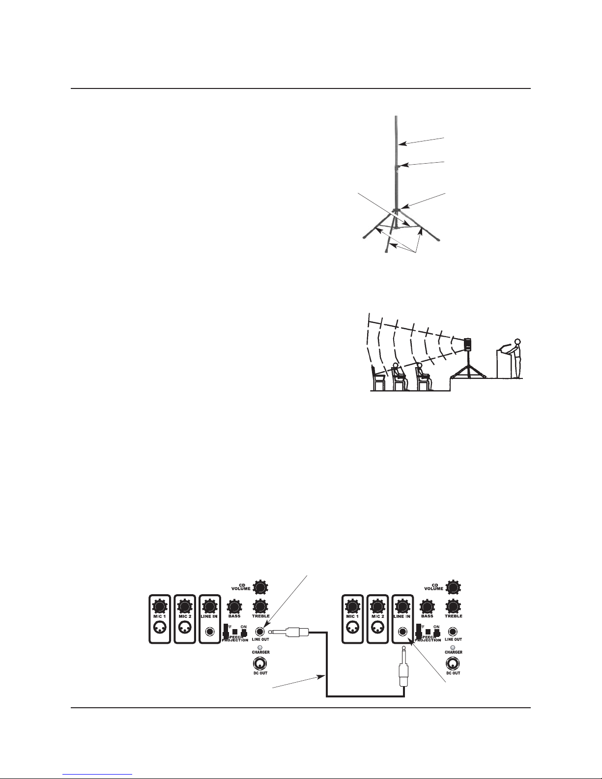
LINE OUT . . . . . . . . . .Unbalanced, mixed, Line-out connector to connect to another Audio System or
other system. The output is post source level — any input volume level
fluctuations will affect the output signal level.
DC OUTPUT . . . . . . . .12 VDC, 300 milliampere (maximum) output connector to power auxiliary
equipment such as an outboard wireless receiver, recorders, etc.
AUDIO SYSTEM OPERATION
1. Turn the MIC 1, MIC 2, WIRELESS LEVEL, CD VOLUME, and LINE IN level control knobs fully
counterclockwise (lowest output).
2. Turn the BASS and TREBLE control knobs to the mid-point (12 o’clock position).
3. If necessary, connect microphones to the MIC 1 and MIC 2 connectors.
4. If necessary, connect an audio source to the LINE IN connector.
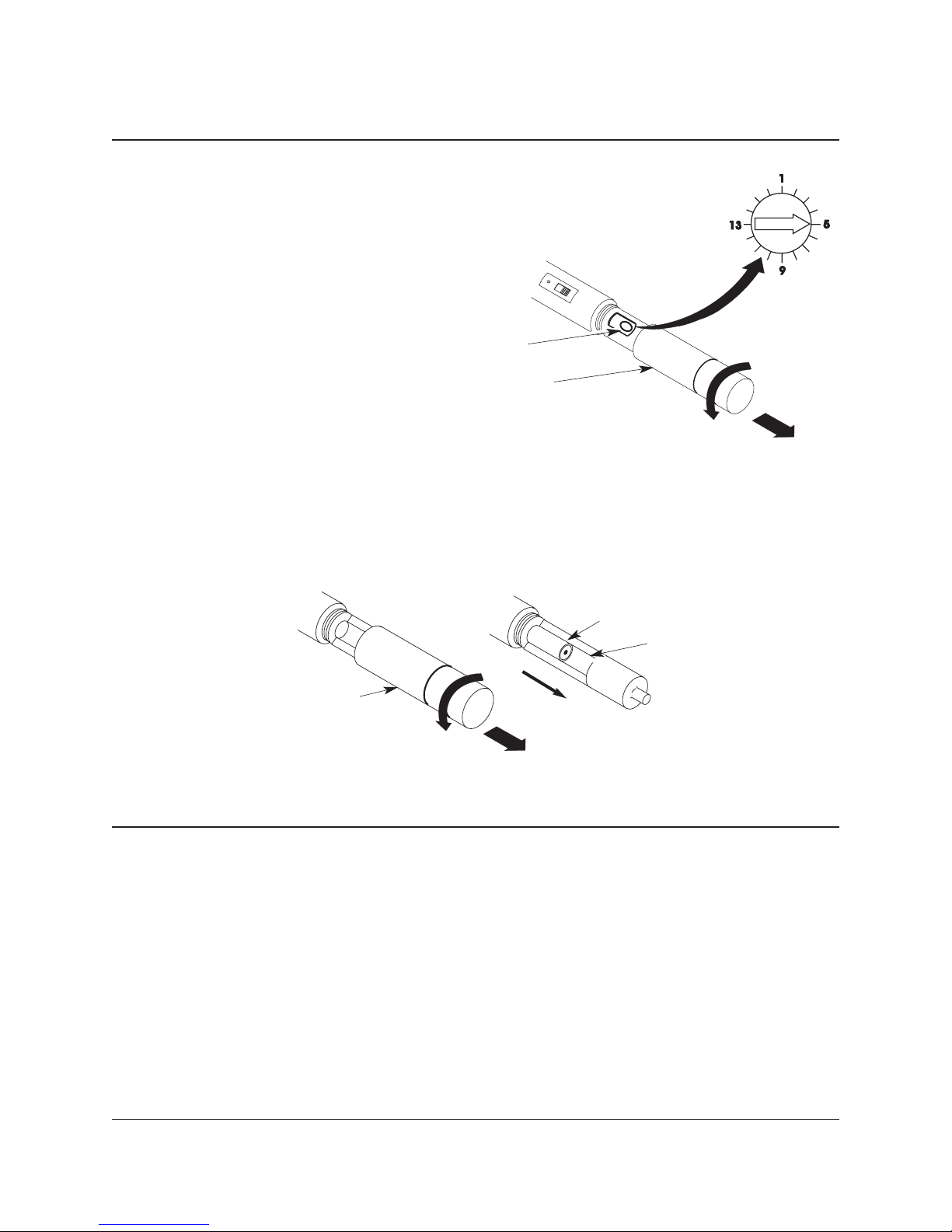
5. Make sure that the Wireless Microphone and the Wireless Receiver are set to the same channel
(refer to the paragraph Wireless Operation).
6. Place the POWER ON rocker switch into the ON position.
7. Slowly adjust the Level Input control knobs to the desired volume (turning clockwise).
8. Adjust the BASS and TREBLE controls for the desired performance quality.
9. For outdoor speech applications, press the SPEECH PROJECTION push button. For standard
applications (music and indoors), leave the SPEECH PROJECTION push button off (out position).
FEEDBACK
Warning! Avoid conditions that cause feedback. Feedback can damage the Audio System and
cause serious injury (hearing)!
Feedback is a shrill sound generated by a microphone picking up sound from a speaker and re-
amplifying the sound. Once initiated, it is a self-sustaining phenomenon.
Specific Feedback causes are:
1. Microphones too close to loudspeakers or a microphone and a loudspeaker facing each other.
2. Volume level is set too high for the performance space.
3. Loudspeaker output is reflecting from hard surfaces to the microphone.
Avoid Feedback by doing the following:
1. Point microphones away from speakers.
2. Place speakers in between the microphone and the audience, each facing away from each other.
3. Reduce output levels when Feedback occurs.
4. Use sound dampening materials over hard surfaces such as curtains and sound dampening foam.

7
CD PLAYER PANEL OPERATION
The CD Player audio output feeds directly to the Audio System internal mixing bus combining the signal
with other input signals.
Load a disc onto the CD Player by inserting it into the slot at the top of the CD Player with the disc label
facing upward.
Caution: To avoid noise at shut off, turn the CD Player off before turning off the main power
switch.
CD VOLUME . . . . . . . .Located below the CD Player Panel. Turn the knob clockwise to increase signal
output level.
OPERATION CONTINUED
CD Player Panel
POWER . . . . . . . . . . .Press the POWER push button to turn the CD Player on and off.
EJECT . . . . . . . . . . . .Press the EJECT push button to eject the disc from the Player. If the disc is not
removed, it re-enters the CD Player ten-seconds after pressing the EJECT push
button.
PLAY/PAUSE . . . . . . .Press the PLAY/PAUSE push button to initiate playback of a disc. Pressing the
PLAY/PAUSE push button when a disc is playing will pause the disc playback until
the push button is pressed again.
UP . . . . . . . . . . . . . . .Press the UP push button to select the next disc track. Press and hold the UP
push button to fast forward on the current track.
DOWN . . . . . . . . . . . .Press the DOWN push button to select the previous disc track. Press and hold the
DOWN push button to fast backward on the current track.
TOP . . . . . . . . . . . . . .Press the TOP push button once to playback the disc first track.
RANDOM . . . . . . . . . .Press the RDM push button to playback all tracks on the disc in a random order.
REPEAT . . . . . . . . . . .Press the RPT push button one time to repeat playback of the selected track
continuously. RPT will appear on the display. Press the RPT push button a second
time to stop continuous playback.

8
OPERATION CONTINUED
WIRELESS SYSTEM
Warning! Do not expose the equipment to moisture, rain, or mechanical shock (such as
dropping onto a hard surface).
The Wireless System consists of a 16-channel Wireless Receiver and a 16-channel Wireless
Microphone.
WIRELESS RECEIVER CHANNEL SELECTION
Before using the Wireless System, select a wireless frequency
channel on the Wireless Receiver Panel.
1. Locate the receiver CHANNEL selector knob on the Series
100 Panel.
2. Turn the CHANNEL selector knob to one of the 16-
channels.
WIRELESS RECEIVER OPERATION
VOLUME . . . . . . . . . .Wireless Receiver VOLUME control knob. Turn the knob clockwise to increase the
signal level.
rx . . . . . . . . . . . . . . . .LED illuminates when a wireless signal is transmitted and received.
CHANNEL . . . . . . . . .Selects one of the Wireless Receiver 16 frequency channels.
Note: Signal interference on the selected channel from other RF systems in the area may cause
problems with the selected frequency channel. Change the selected channel on both the
Receiver and Microphone if a problem develops with Wireless Microphone transmission.
WIRELESS MICROPHONE OPERATION
Warning! Do not expose the wireless microphone to moisture, rain, or mechanical shock (such
as dropping onto a hard surface).
1. Make sure that the Wireless Microphone CHANNEL SELECTOR is set to the same Wireless Receiver
frequency channel. Refer to Wireless Receiver Channel Selection.
2. Place the Wireless Microphone ON-STANDBY-OFF POWER Switch into the ON position.
a. The Red Power On LED will flash.
b. If the Red Power On LED illuminates continuously the Microphone Batteries have a low charge
and should be replaced.
3. Place the Audio System Main Power Switch into the ON position.
4. Either of the two rx Indicator LED’s on the Wireless Receiver illuminate when wireless signals are
being transmitted and received.
Caution: Harmful feedback can occur when walking in
front of a sound system or loudspeaker with a
wireless microphone. Always point the
microphone away from loudspeakers.
Wireless Receive Panel
Red Power LED
On-Standby-Off Switch
Wireless Microphone

9
MAINTENANCE
AUDIO SYSTEM
1. Clean the exterior case with a clean cotton cloth and a mild detergent. Do not use harsh detergents
or an abrasive.
2. Clean textured areas and controls with a dry bristle brush.
WIRELESS MICROPHONE
1. Clean the Wireless Microphone Windscreen as follows.
a. Unscrew the wire-mesh cap counterclockwise and remove the wire-mesh cap from the
Microphone body.
b. Remove the windscreen (foam sheet) from the wire-mesh cap.
c. Wash the windscreen in a mild detergent.
d. As soon as the windscreen has dried, replace it in the wire-mesh cap and screw the wire-mesh
cap onto the Microphone body clockwise.
WIRELESS MICROPHONE CHANNEL SELECTION
1. Unscrew and remove the Wireless Microphone Battery Cover on the lower end of
the Wireless Microphone.
2. Using a miniature electronic screwdriver, set the Wireless Microphone CHANNEL
SELECTOR to the same channel frequency selected on the Wireless Receiver.
3. Replace the Battery Cover.
Wireless Microphone
Wireless Microphone
Battery Cover
Wireless Microphone
Channel Selector
OPERATION CONTINUED
WIRELESS MICROPHONE BATTERY REPLACEMENT
1. Unscrew and remove the Wireless Microphone Battery Cover on the lower end of the Wireless
Microphone.
2. Place two AA Alkaline batteries onto the Battery Slot. The positive end of each battery must face the
bottom of the microphone.
3. Replace the Battery Cover.
Wireless Microphone
Battery Cover
Wireless Microphone
AA Alkaline Battery
Battery Slot
+

10
TROUBLESHOOTING
Condition Possible Cause
There is no sound (the Main Power
LED is not illuminated
The Main Power Switch is in the off position.
The batteries are discharged (LED flashes).
The Charge Indicator does not
illuminate.
Blown Fuse
There is no sound and the Main Power
LED illuminates.
There is no output from the signal source.
An input cable is not plugged into the jack.
The signal level control is low or set to off.
A plug is inserted into a switched loudspeaker
output but the cord is not connected to a
loudspeaker.
Short battery life There is a short circuit in an external cable or
loudspeaker.
Total external loudspeaker impedance is less than
four ohms.
Batteries are not fully charged.
Batteries need replacement.
Distorted sound There is a poor connection on an input cable.
The input signal level is too high.
Excessive hum or noise The input cable is not shielded.
System is not using a balanced microphone.
Wireless System has no sound (the rx
Indicator illuminates).
The Wireless Volume Control is set too low or off.
Wireless System has no sound (the rx
Indicator does not illuminate).
The Main Power Switch is not turned on.
The Wireless Microphone is not turned on.
The Wireless MIcrophone batteries are discharged.
The Wireless receiver and Wireless Microphone
are set to different channels.
Table of contents
Other Wenger Stereo System manuals