Wenger SoundLok VAE User manual

Contents
Overview. . . . . . . . . . . . . . . . . . . . . . . . . . . . . . . . . . . . . . . . . . 2
Black Box Installation . . . . . . . . . . . . . . . . . . . . . . . . . . . . . . . . 3
Installation Instructions
SoundLok®
VAE®Installation
©Wenger Corporation 2019 Printed in USA 2019-01 Part #270A586-03
Wenger Corporation, 555 Park Drive, P.O. Box 448, Owatonna, Minnesota 55060-0448
Questions? Call.....USA: (800) 4WENGER (493-6437) • Worldwide: +1-507-455-4100 • wengercorp.com
Important Mounting Instructions
When wall mounted, the black box containing the
VAE processor must be securely attached to the
wall in accordance with the installation instructions.
FAILURE TO FOLLOW INSTALLATION
INSTRUCTIONS MAY RESULT IN INJURY.
!CAUTION
These instructions cover the installation of Wenger’s VAE®
(Virtual Acoustic Environments) electronics package in new installations
where the room contains all necessary internal components like speakers,
microphones and VAE control panel.

2
"Black box" is the term used throughout this
manual to describe the assembled black
electronics rack containing the VAE processor
and related cables and components.
Most installations will allow the black box to be
located in its preferred position, sitting on the top
of the VAE equipped Wenger SoundLok room.
In applications where that space is not available
or desirable, the black box can be mounted to
the wall on the side of the room.
In either location, the black box will be ducted
through an 8" x 20" hole in the closure panel
and covered with a grill, providing necessary
ventilation.
If the black box must be wall mounted,
determine the best mounting location.
It can be mounted on any side of the VAE
equipped SoundLok room but only in an area
that is inaccessible to non-service personnel
behind closure panels requiring tools for removal.
Overview
Black Box mounted to
top of Ceiling Panel
(Preferred Position)
Black Box
mounted outside
of Side Panel
Closure
Panel
Closure
Panel
Closure
Panel
Black Box mounted to top of Ceiling Panels
(Preferred Position)
Black Box mounted to wall on side of room
Security
Grill

3
Black Box Installation
Attach a hanger bracket to both sides of the rack using
two #10-16 x 0.75" self drilling screws in each side.
Use the bottom set of holes in the mounting brackets for
mounting the rack to the ceiling. Use the top set of holes
in the mounting brackets to mount the rack to a side wall.
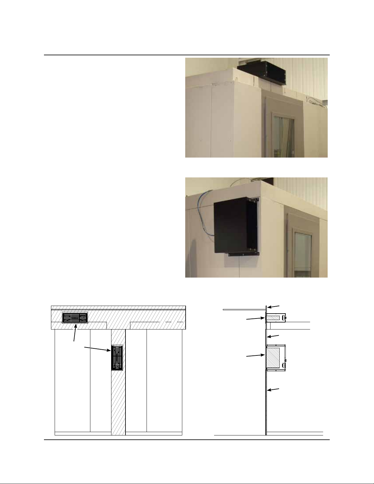
1. Mount the rack to either the ceiling or side panel
using the following methods.
Mounting Rack with Ceiling Installation
a. Position the rack on the ceiling panels. The rack
must be square with the front panels and positioned
¾" (2 cm) back from the front panels to allow
clearance for the installation of closure panels.
b. Attach the rack to the ceiling panels using one
#10-16 x 0.75" self drilling screw in both of the rear
holes and both of the middle holes of the hanger
brackets. The front two holes of the hanger brackets
are not used.
or
Mounting Rack with Side Panel Installation
a. Position the rack at the front of the side panel.
The rack must be square with the front panel and
positioned ¾" (2 cm) back from the front panel to
allow clearance for the installation of closure panels.
b. Attach the rack to the side panel using a
#10-16 x 0.75" self drilling screw in the middle hole
of the top hanger bracket. Level the rack and attach
screws in the five remaining holes in the hanger
brackets.
Bottom Set of Holes
for Ceiling Installation
Top Set of Holes for
Side Panel Installation
¾" (2 cm)
Offset from
Front Panels
¾" (2 cm)
Offset from
Front Panel

4
Black Box Installation (continued)
2. Install the flash memory card (connector end first)
into the slot in the back of the VAE processor labeled
COMPACT FLASH. It will fit into this slot in only one
orientation. The contacts will engage during the last
0.125" of insertion. When properly installed, only
about 0.125" of the card will protrude beyond the
socket.
3. Holding the VAE processor near the black box,
connect the two speaker cables found inside the
tray to the VAE processor. Connect the 4-pin
connector marked "1-2" to the jack in the
VAE processor marked "1-2". Similarly,
connect the 4-pin connector marked "3-4" to
the jack in the VAE processor marked "3-4".
4. Connect the control cable. This is the cable that
extends from the top of the power panel.
Insert the connector at the end of this cable through
the entrance clamp in the black box and plug it into
the socket labeled REMOTE KEYPAD on the back
of the VAE processor inside the black box.
The locking tab on the connector should be positioned
upward.

5
5. Connect the microphone cables. Locate the
microphone panel located toward the left-hand side
as entering the room. Connect a microphone cable
between the connector on the top of this panel and
the jack labeled "MICROPHONE 1" on the back of
the VAE processor inside the black box. Repeat for
the other microphone panel using the jack labeled
"MICROPHONE 2".
Both microphone cables should be individually
inserted through the entrance clamp in the black box
before connecting to the VAE Processor.
6. Connect the power cable provided with the
VAE processor. It installs between the IEC connector
on the back of the VAE processor and the receptacle
inside the black box. Bundle and position the excess
cable out of the way above the VAE processor.
Box cut-away is being shown for clarity.
Black Box Installation (continued)

6
7. Install four clip nuts into the four available holes in
the front panel of the black box. Install them with
the "nut" portion inside the black box. Using these
clip nuts, install the processor into the black box
with the four screws and washers provided with the
VAE processor.
Carefully guide the attached wiring into the black box.
IMPORTANT: Be sure to use the plastic washers
that are provided.
8. Connect the four speaker cables. These cables
connect each corner panel (containing the speakers)
to the black box. Locate the room corner panel
directly to the left of the door as you enter the room.
Connect one end of the first cable to the mating
connector at the top of this corner panel where it
protrudes through the ceiling rail.
Connect the other end to the left-most speaker
connector on the black box.
Move to the next corner in a clockwise direction
and connect a speaker cable between that corner
and the next speaker connector on the black box.
Continue around the top of the room in a clockwise
direction connecting the remaining two speaker cables
between the corner panels and their respective
connectors in the black box.
Black Box Installation (continued)

7
9. Be sure the VAE system power switch on the power panel is in the OFF position.
Plug the main black box power cable into the mating connector on any other
available panel. Secure this cable to the adjacent ceiling or wall panel using a
cable clip and self-drilling screw positioned within 6" (15 cm) of the power panel end.
10. Push the power switch on the VAE unit to the
"ON" position (depressed).
Black Box Installation (continued)

8
This page is intentionally blank.
Table of contents
Other Wenger Stereo System manuals