5
SETUP
BEFORE OPERATING
Refer to the Audio System Series 400 Owner’s Manual and the Spirit Series M Users Guide for
additional information regarding set up and component connections.
1. Make sure the Audio System Power Distribution Unit On-Off Switch is in the OFF Position.
2. Connect a power cord from the Power Distribution Unit to a 120 VAC power source. All components
are powered by this component.
3. Connect the QSC RMX850 Amplifier CHANNEL 1 OUTPUT connector to a Community MVP28
Monitor Loudspeaker INPUT connector and the Amplifier CHANNEL 2 OUTPUT connector to the other
Community MVP28 Monitor Loudspeaker INPUT connector.
4. Make sure that the QSC RMX850 Amplifier, the Rane ME15B Graphic Equalizer, and the Series 400
Mixer are connected as outlined above, Connection, steps 1 to 4.
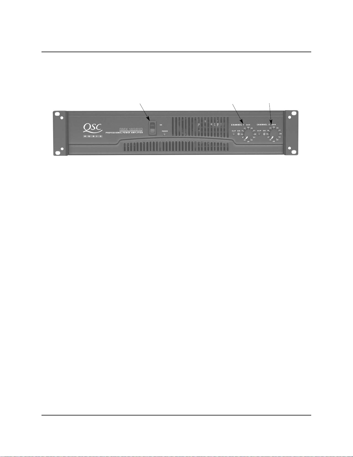
INITIAL GRAPHIC EQUALIZER SETTINGS
Refer to the Audio System Series 400 Owner’s Manual and the Spirit Series M Users Guide for
additional information regarding settings and power up procedures.
1. Make sure that all power switches are OFF.
2. Depress the CHANNEL 1 and CHANNEL 2 BYPASS switches.
3. Place the Level Slide Controls for both channels to the mid-position (0 dBA.).
4. Place the CHANNEL 1 and CHANNEL 2 LEVEL controls at the mid-position (about 12 o’clock).
Level Slide ControlsChannel 1
Bypass Switch Channel 2
Bypass Switch Power Switch
Channel 1 Level
Control Channel 2
Level Control
Channel 1
Overload Indicators Channel 2
Overload Indicators
Rane ME15B Graphic Equalizer Front Panel
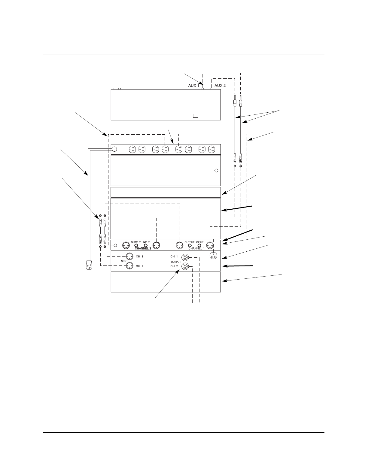
CONNECTION
1. Using a pair of Internal Cables, connect the Series 400 Mixer AUX 1 and AUX 2 to the Graphic
Equalizer CHANNEL 1 INPUT and CHANNEL 2 INPUT connectors.
2. Connect the Power Cord from the Graphic Equalizer to an unused receptacle on the Power
Distribution Unit.
3. Using a pair of Internal Cables, connect the Rane ME15B Graphic Equalizer CHANNEL 1 OUTPUT
and CHANNEL 2 OUTPUT to the Amplifier CHANNEL 1 INPUT and CHANNEL 2 INPUT connectors.
4. Connect the Power Cord from the Amplifier to an unused receptacle on the Power Distribution Unit.
5. Using the pair of Speaker Cables, connect the Amplifier CHANNEL 1 OUTPUT connector to a
Community MVP28 Monitor Loudspeaker INPUT connector and the Amplifier CHANNEL 2 OUTPUT
connector to the other Community MVP28 Monitor Loudspeaker INPUT connector.