Wentworth Technology SpeedTHRU User manual

Charge Batteries First – label up, amber light--charging, green--fully charged. You may use them
before they are fully charged.
Pull Cable – Old wire is brittle and will fail! Don't shortcut this step. One Gray spool (for the
microphone) and one Black spool (for the loop and speaker) is included.
Choose Base Station location – Power up the base, load a battery in a headset and walk around
the restaurant to insure you have good coverage of all areas, inside and outside. Stay away from
metal when mounting the base, even metal junction boxes inside the wall—metal blocks radio waves.
Refer to the laminated Quick Start Guide for instructions on installing batteries in the headsets.
Remove old equipment—if necessary. If there is a timer on site, take care to identify the timer wires
connected to the old equipment. A PHOTO of the wires is a good idea.
Mount the Base – Hardware kit is in the base station box. Center photo
(bottom to top)
Wall spacer
plate for base hinge, Zip anchors & pan head screws, Metal strike and flat head screws, Dolphin
connectors for mic, loop and speaker connections outside, strain relief mounts and small wire ties.
Mount the detector block to the lower left of the base as shown. Keep your wires neat and tidy!
If you use a drill bit to “oval out” one hole in the base hinge, (it makes it easier to get it level).
Installation Guide 10/23/2012 Page 1

Make the Base and Detector Block Connections – Tin all wires! A wiring diagram in included in
the detector kit as well as hardware to mount the block. Take care to mount it with the right side up!
•Step 1: Cut a short piece of Black cable to connect the Detector Block “Relay A” (“5” positive, “6”
ground) to the Base Station “M” (positive) and “O” (ground) terminals.
•Step 2: Connect the power supply to the detector block “1” (positive-look for ”white line” on
wire) “2” (ground).
•Step 3: Strip back about 10” of the jacket on the Black jacket cable which carries the loop
(white/green) & speaker (black/red) wires. Take care to twist the loop wires (white/green) since
these are “active” loop wires and movement between the wires may cause a false detection.
•Step 4: Attach loop (W/Gn) to detector block “8” and “7” (no polarity). Attach speaker (R/Bk) to
base terminal “K” and “L” (no polarity) Recovering the wire with the black jacket makes for a neat
job.
•Step 5: The Gray jacket cable is the microphone (W/Gn/Drain) to base terminals “P” (drain).,
“Q” and “R” (no polarity). Use a small piece of gray jacket to cover the bare drain wire.
Installation Guide 10/23/2012 Page 2

•Mount Speaker and Mic in the Speaker Post or Menu Board
•The microphone location is most important! 42” to 52” above the drive thru surface and
positioned at the point the customer will stop is best. Bascially, GET THE MICROPHONE AS
CLOSE TO THE CUSTOMER AS POSSIBLE!
•The speaker location is less important. Keep the speaker and mic at least 18” apart. The
speaker can be put in the bottom of the speaker post if space allows or hung under the menu
board, even facing straight down (which also helps weather resistance)
•Foam has been provided to “cradle” the microphone and speaker. Direct contact with the
speaker post may transmit vibration which is “sound” to a microphone.
•Keep the wire entrance at the bottom to serve as a “weep hole” to allow water to drain.
•A couple illustrations of how to mount the speaker/mic assemblies.
In situations where NO shelf is provided to hold the foam, is may be necessary to screw into the face
of the microphone and speaker boxes to hold them in place. Just stay to the outside edge of the
boxes and you will miss the microphone and speaker inside. Only do this if absolutely necessary.
Solder ALL wire connections – Microphone, Speaker and Loop. Use “grease-filled” Dolphin
connections to cover the soldered connections. Place wire connections in any “up” position so that
water does not run down the wire into the connections.
Installation Guide 10/23/2012 Page 3

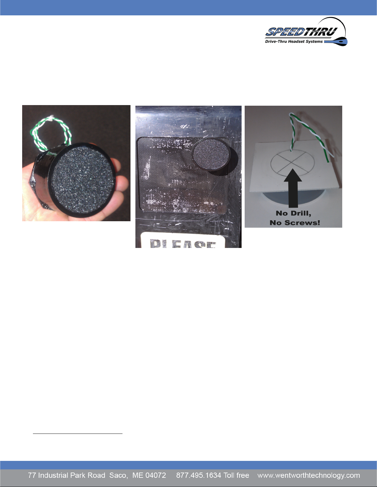
•Alternate microphone. In some situation we may have provided a small surface mount
microphone of which we have two types. One 3” round mic or a 3” by ½ by ½ mic. Both of
these are made to address menu boards where no good mounting place is available for the
standard microphone at the proper height. These can be mounted with screws in addition to a
velco pad to isolate vibration. Do not screw the microphone tightly. Keep screws to the
outside ½ inch of the circle.
Once finished with the microphone, speaker and loop, power up the system to test the detection
operation and set volumes.
We send the base stations out with a USER Password of 0000 which can be changed.The Tech
Password (permanent) is 2580 –(the only four digits in a row) but do not share this.
Normal “Inbound sound” settings range from 4 to 6 generally. Keep it as low as possible as
higher volume levels increase the noise as well.
Normal “Outbound” setting range from 6 to 10. Set Outbound Day and Outbound Night to the
same level unless the Night program is used, then adjust to preferred levels and set the clock.
Grill speaker volumes can be set to preference and there is a potentiometer behind the left front
cover to adjust the balance between the “customer/ order post” and the “order taker”
Use the laminated QUICK START TRAINING GUIDE and accompying Training Sheet to train the
team. Training support is available by calling Wentworth Technology.
Timer Connections: Call Wentworth Technology (207) 571-9744 or visit
WentworthTechnology.com and click on “Support” then select “Support Documents”.
Installation Guide 10/23/2012 Page 4

Mount the battery charger with the Velcro pads included. Remove the feet if wall mounted. Wall
mounting will protect the charger from spills. If possible, let the Velcro “cure” for 24 hours before
mounting the charger for good adhesion. Ask the team to put it in place later.
Headset hooks are included that can be mounted were the manager directs.
Other items: Give the manager the headset cushions, foam microphone covers and “listen-only”
headset markers.
Clean up anything remaining from your install. Give any old equipment to the manager. Obtain a
signature on the Installation report and return it to WT.
Installation Guide 10/23/2012 Page 5
Other manuals for SpeedTHRU
1
Table of contents
Other Wentworth Technology Headset manuals