Werner Dosiertechnik POOLKLAR Touch Basic User manual

WERNER Dosiertechnik
___________________________________________________________________________________________________________
Subject to technical modifications
-----------------------------------------------------------------------------------------------------------------------------------------------------------------------------------------------------------------------------------------------------------------------------------------------------------------
Hettlinger Strasse 17 Tel. +49 (0) 8272/ 98697- 0 www.werner-dosiertechnik.de
Measuring, control and dosing
technology
for private pools
POOLKLAR Touch Basic
As of year of mfg. 04/2021 serial no. 80487
Measuring, control and dosing technology for pH regulation and disinfectants
BA MR 007-01 POOLKLAR_Touch-basic_V1.1 EN.docx

WDT POOLKLAR Touch Basic
English translation of the original German version of the operation manual - Version 1.1 (HW CB36 –FW V1.0.0) 2021_07_09 2/38
Table of contents
1About this manual .........................................................................................................................................................................4
1.1 Scope of applicability................................................................................................................................................................4
1.2 Target group .............................................................................................................................................................................4
1.3 Storage of the manual ..............................................................................................................................................................4
1.4 Further information..................................................................................................................................................................4
1.5 Symbols used............................................................................................................................................................................4
2Safety.............................................................................................................................................................................................5
2.1 Intended use.............................................................................................................................................................................5
2.2 Safety notices............................................................................................................................................................................5
3Important facts about swimming pool water properties ..............................................................................................................6
3.1 Auxiliary hygiene parameters ...................................................................................................................................................6
3.2 pH value....................................................................................................................................................................................6
3.3 Redox voltage ...........................................................................................................................................................................6
3.4 free chlorine .............................................................................................................................................................................6
3.5 combined chlorine....................................................................................................................................................................6
4Scope of delivery –device description ..........................................................................................................................................7
4.1 Scope of delivery.......................................................................................................................................................................7
4.2 Check for transport damage.....................................................................................................................................................7
4.3 Identification of the device.......................................................................................................................................................7
4.4 Device description ....................................................................................................................................................................7
5Installation.....................................................................................................................................................................................8
5.1 Select the installation site.........................................................................................................................................................8
5.2 Mounting the device on the wall..............................................................................................................................................8
5.3 Voltage supply ..........................................................................................................................................................................8
5.4 Installation notices....................................................................................................................................................................8
5.5 Measuring water prefilter.........................................................................................................................................................8
5.6 Temperature sensor .................................................................................................................................................................8
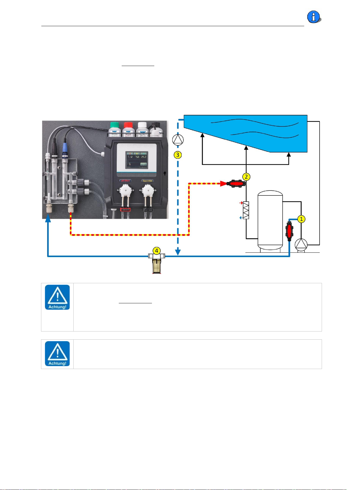
5.7 Installation suggestion..............................................................................................................................................................9
6Notices regarding commissioning and ongoing operation ..........................................................................................................10
6.1 Control parameters.................................................................................................................................................................10
6.2 pH and redox electrode ..........................................................................................................................................................10
6.3 Dosing head(s) ........................................................................................................................................................................10
6.4 Measuring cell flow.................................................................................................................................................................10
6.5 Chemicals................................................................................................................................................................................10
6.6 Disinfectants ...........................................................................................................................................................................11
6.7 Fresh water replenishment.....................................................................................................................................................11
6.8 Floor cleaning .........................................................................................................................................................................11
7Electrical connection ...................................................................................................................................................................12
7.1 Open and close the housing ...................................................................................................................................................12
7.2 Insert lines ..............................................................................................................................................................................12
7.3 Overview of the connection diagram .....................................................................................................................................13
7.3.1 The I/O board CB36............................................................................................................................................................13
7.3.2 The HMI_eDIPTFT32 V1.0 display adapter.........................................................................................................................14
7.3.3 The MV_Aptr_CB-36_V1.0 measuring amplifier................................................................................................................15
7.4 External functions...................................................................................................................................................................15
7.4.1 Input External OFF –release contact .................................................................................................................................15
7.4.2 Temperature control..........................................................................................................................................................15
8Operating the touch screen.........................................................................................................................................................16
8.1 The statuses in automatic mode.............................................................................................................................................17
8.1.1 Status 1. Dosing –dosing delay..........................................................................................................................................17
8.1.2 Status pH stop dosCL –pH priority dosing.........................................................................................................................17
8.1.3 Status Auto (automatic).....................................................................................................................................................17
8.1.4 Status standby ...................................................................................................................................................................17
8.1.5 Time Limit - Dosing time monitoring alarm .......................................................................................................................18

WDT POOLKLAR Touch Basic
English translation of the original German version of the operation manual - Version 1.1 (HW CB36 –FW V1.0.0) 2021_07_09 3/38
8.1.6 General alarm ....................................................................................................................................................................18
8.1.7 Temperature fault..............................................................................................................................................................18
8.1.8 Measuring amplifier fault ..................................................................................................................................................18
8.2 The menu structure ................................................................................................................................................................19
8.2.1 Navigating the menu..........................................................................................................................................................20
8.2.2 The header.........................................................................................................................................................................20
8.2.3 Quick Info...........................................................................................................................................................................21
8.3 Main menu..............................................................................................................................................................................21
8.3.1 Main menu Set (settings) ..............................................................................................................................................21
8.3.1.1 Main menu Set pH...............................................................................................................................................22
8.3.1.2 Main menu Set Redox mV (disinfection) .............................................................................................................22
8.3.1.3 Main menu Set Output (dosing performance) ....................................................................................................23
8.3.1.4 Main menu Set Temperature ..............................................................................................................................24
8.3.1.5 Main menu Set Delay...........................................................................................................................................24
8.3.1.6 Main menu Set System........................................................................................................................................25
8.3.1.7 Main menu Set System Date/ Time ................................................................................................................25
8.3.1.8 Main menu Set System Language...................................................................................................................25
8.3.1.9 Main menu Set System Reset .........................................................................................................................25
8.3.2 Main menu Service........................................................................................................................................................26
8.3.2.1 Main menu Service Input Input test....................................................................................................................26
8.3.2.2 Main menu Service Output (Output test)............................................................................................................26
8.3.2.3 Main menu Service Info.......................................................................................................................................27
8.2.2 Main menu Calibration..................................................................................................................................................27
8.2.2.3 Main menu Calibration pH (2-point calibration with pH electrode)....................................................................28
8.2.2.4 Main menu Calibration Phenol (manual calibration by means of tablets- or drop-measurement).....................30
8.2.2.5 Main menu Calibration mV Redox.......................................................................................................................32
8.2.3 Main menu Log .............................................................................................................................................................33
8.2.3.3 Main menu Log Event..........................................................................................................................................33
8.2.3.4 Main menu Log Calibration .................................................................................................................................33
9. Maintenance and cleaning ..........................................................................................................................................................34
9.1 Fine filter (OPTIONAL).............................................................................................................................................................34
9.2 pH and redox electrode ..........................................................................................................................................................34
9.3 Dosing valves ..........................................................................................................................................................................34
9.4 Dosing heads...........................................................................................................................................................................34
10. Decommissioning - overwintering - storage................................................................................................................................35
11. Technical data..............................................................................................................................................................................35
12. Change history - POOLKLAR Touch Basic device series................................................................................................................35
13. Commissioning protocol - default table ......................................................................................................................................36
14. Personal notes.............................................................................................................................................................................37
15. Spare parts list.............................................................................................................................................................................38

WDT POOLKLAR Touch Basic
English translation of the original German version of the operation manual - Version 1.1 (HW CB36 –FW V1.0.0) 2021_07_09 4/38
1About this manual
1.1 Scope of applicability
This manual describes the installation, commissioning and operation of the device.
The manual covers the POOLKLAR Touch Basic for the hardware and firmware versions indicated in the cover sheet and footer.
1.2 Target group
Only persons who have received proper instructions regarding the device functions may operate the device. Electrical and water-
side connection work may only be conducted by appropriately trained specialists.
1.3 Storage of the manual
All manuals for the device as well as those for the installed components must be stored in the immediate vicinity of the device and
be accessible to the operating personnel at all times.
1.4 Further information
Further information about special topics, e.g., design of the dosing performance or description of the operating parameters, is
available from your specialist dealer.
1.5 Symbols used
The following types of safety notices and general notices are used in this document.
DANGER!
“DANGER” denotes a safety notice which, if disregarded, will directly result in
death or serious injury!
WARNING!
“WARNING” denotes a safety notice which, if disregarded, may result in death or serious injury!
CAUTION!
“CAUTION” denotes a safety notice which, if disregarded, may result in minor or moderate injury!
ATTENTION!
“ATTENTION” denotes a safety notice which, if disregarded, may result in property damage!
Notice
A notice denotes information which, if disregarded, may result in operational disruptions.
Tip
A tip denotes information that may result in improvements in the operating process.

WDT POOLKLAR Touch Basic
English translation of the original German version of the operation manual - Version 1.1 (HW CB36 –FW V1.0.0) 2021_07_09 5/38
2Safety
2.1 Intended use
The POOLKLAR Touch Basic device is intended for regulating the pH value, disinfection and (optionally) the pool water temperature
control in private swimming pools.
2.2 Safety notices
The operation manual must be consulted prior to installation, commissioning and maintenance work. Following the
commissioning, the manual must be made available to the operator. In your own interest, please pay attention to the safety
notices contained in this manual.
Always handle chemicals with special care!
Please contact your chemicals supplier for information about the required safety measures when handling chemicals.
WARNING!
There is a risk of chemical burns and poisoning!
Pay attention to the relevant regulations when handling chemicals!
-Never mix different chemicals with each other.
-Only use chemicals that have been approved for the treatment of swimming pool water.
-Wear suitable protective clothing when handling chemicals.
Further safety information about the chemicals used is available from your chemicals supplier.

WDT POOLKLAR Touch Basic
English translation of the original German version of the operation manual - Version 1.1 (HW CB36 –FW V1.0.0) 2021_07_09 6/38
3Important facts about swimming pool water properties
3.1 Auxiliary hygiene parameters
The following information is meant to offer a preliminary overview about the most important auxiliary hygiene parameters in the
treatment of swimming pool water. Additional literature is available from your swimming pool dealer, the chemicals suppliers, or
the book trade. The information provided here refers to DIN EN 16713 for swimming pool water in private pools. (applicable as of
08/2016)
Devices that are operated outside of the EU should comply with the county-specific regulations and statutes.
3.2 pH value
The pH value has a decisive effect on the chemicals added to the swimming pool cycle. If the pH value is too high, it negatively
affects the germ-killing speed of disinfectants containing chlorine. There is an increased likelihood of lime precipitation and water
clouding. If the pH value drops too low for an extended period of time, leading to an increase in the water's corrosivity, there is a
risk of damage to the treatment system and the pool.
According to the standard, values below pH6.8 and above pH7.6 should be avoided. A pH value around pH7 is recommended.
3.3 Redox voltage
The redox voltage is used as a measure for assessing the hygienic pool water quality. The redox voltage indicates the ratio between
reducing substances (organic contaminations) and oxidising power (active chlorine content) in the pool water. The redox voltage is
used as a measure for assessing the hygienic pool water quality. The higher the redox voltage, the faster germs and bacteria will be
killed. To achieve a sufficiently fast germicidal effect, the redox voltage in private pools should also comply with the values
specified by the DIN (German institute for standardization). In this context, the amount of free chlorine measured with the DPD1
method should be between 0.3 and 0.6 mg/l.
The chlorine’s disinfecting power essentially depends on the pool water’s pH value. The higher the pH value, the lower the
disinfecting power and thus the redox voltage. If the pH value decreases, the disinfecting power increases at a constant chlorine
level.
If the redox voltage is far below 700 mV at a free chlorine content between 0.3 and 0.6 mg/l, the complete function of the
swimming pool water treatment must be checked.
According to the standard, a redox voltage above 650 mV should be aimed for. Values below 650 and above 800 mV should be
avoided. A redox voltage around > 700 to 750 mV is recommended.
(According to DIN 19643 for public pools, a redox voltage > 750 mV is required.)
3.4 free chlorine
The chlorine available for disinfection in the pool water is called free chlorine. Free chlorine is detected by means of the DPD1
method.
According to the standard, the free chlorine content should be kept between 0.3 and 1.5 mg/l.
Values below 0.2 and above 2.0 mg/l should be avoided.
3.5 combined chlorine
Combined chlorine is the product of a reaction between organic contaminants introduced in the pool and a chlorine-containing
disinfectant. Combined chlorine causes the characteristic indoor pool smell and may lead to skin irritation and red eyes.
Ideally, the organic chlorine compounds will be retained in the swimming pool filter system and flushed out via the regular
backwashing. If the filter system does not work correctly, or if the backwashing is not conducted in a proper fashion, combined
chlorine may accumulate in the swimming pool cycle. If the water starts smelling of chlorine, it is high time to conduct a chlorine
measurement by means of the DPD3 measuring.
The concentration of combined chlorine results from the difference between the overall chlorine content and the amount of free
chlorine in the water. Pay attention to the instructions of the analytic device's manufacturer when determining the concentration.
Combined chlorine can only be reduced by dilution, i.e., with vigorous backwashing or by a shock chlorination, if applicable.
Consult your swimming pool dealer.
According to the standard, a maximum combined chlorine content of 0.5 mg/l is permissible.
“Chlorine odours” can result above a combined chlorine content of approx. 0.3 to 0.4 mg/l. (characteristic indoor pool smell)
Tip –pH priority dosing
Since the pH value is an elementary factor in the swimming pool water treatment, the dosing of chlorine-containing
disinfectants can be blocked via the pH stop dosCL function, depending on the pH.

WDT POOLKLAR Touch Basic
English translation of the original German version of the operation manual - Version 1.1 (HW CB36 –FW V1.0.0) 2021_07_09 7/38
4Scope of delivery –device description
4.1 Scope of delivery
The POOLKLAR Touch Basic is delivered with the following standard accessories.
- Buffer solutions pH7, pH4, redox test solution
- Electrode cleaner, distilled water
- Electrolyte solution for overwintering
- 2 pc. ½” measuring water ball valve with immersion pipe
- 10 m measuring water pipe 6x1 mm in PE
Customer-specific or order-related modifications are possible.
4.2 Check for transport damage
Please check the device and all accessories immediately upon receipt for transport damage and completeness.
4.3 Identification of the device
For spare part orders and troubleshooting, it is useful to know the device serial number and firmware version. The device serial
number is located on the identification plate on the right side of the control housing. The Firmware version can be called up via the
menu item Service
Info.
4.4 Device description
⑨
1. Flow-through fitting Basic
2. Flow monitoring
3. pH electrode
4. Redox electrode
5. Dosing valve for pH value
6. Dosing valve for disinfection
7. Measuring water backflow
8. Measuring water inlet
9. Buffer solutions
10. Control unit POOLKLAR Basic
11. Dosing pumps SR10
12. Hose bracket Basic
13. Suction sets
(not shown in the
photograph)
③
④
⑩
②
①
⑤
⑥
⑪
⑫
⑧
⑦
⑬
The POOLKLAR Touch Basic is delivered as a ready-assembled unit. All parts are mounted on a plastic plate. This ensures a quick
installation of the device.
For the transport, the electrodes 3+4 are removed from the measuring cell and delivered separately in a protective packing box. In
order to avoid deformation of the dosing hoses during extended storage, the two dosing heads 11 have been pulled off the motor
shaft.
The POOLKLAR Touch Basic is equipped with a touch-sensitive touch screen. This function is activated by touching a symbol (ICON).
The calibration menus come with additional text-based instructions.
In order to eliminate the risk of confusing the two chemicals as far as possible, the dosing technology is colour-coded throughout.
The colour-coding extends from the suction set over the associated dosing pump to the dosing valve.
The parts used for pH value regulation are located to the left and coded in red. The components used for disinfection are located
on the right and coded in yellow.
CAUTION!
If the two chemicals are switched, this leads to a malfunction of the addition of chemicals to the pool water! This
may result in significant overdosing!

WDT POOLKLAR Touch Basic
English translation of the original German version of the operation manual - Version 1.1 (HW CB36 –FW V1.0.0) 2021_07_09 8/38
5Installation
5.1 Select the installation site
A freely accessible installation site should be selected to facilitate operation and subsequent maintenance tasks. The installation
site must be protected from frost and the device may not be exposed to direct sunlight.
5.2 Mounting the device on the wall
Select the installation height so that the display is located at eye level. Measure the three drill holes on the mounting plate and
mark their location on the wall.
5.3 Voltage supply
The devices' voltage supply (230 VAC) can be realised in two ways.
1. Continuous voltage:
This variant has advantages when there is a risk of condensation moisture, e.g., in a technical shaft at the head of the
pool outdoors.
2. Voltage supply parallel to the filter pump
This variant can be selected for dry installation rooms. The advantage then lies in the reduced operating hours of the
electronics.
In addition, the devices are equipped with an external OFF release contact. The dosing can be temporarily deactivated via this
contact, which is interlocked with the filter control.
5.4 Installation notices
Only good pool hydraulics can achieve a satisfactory control of the two auxiliary hygiene parameters, pH value and redox voltage.
The dosed chemicals must reach all areas of the pool within a short time. Even under stress, the concentrations measured at
different points must be approximately the same. The measuring water should be identical to the pool water and must reach the
measuring cell as quickly as possible. This is the only way to quickly detect changes in the water quality and rebalance them by
adding corrective chemicals.
If the pool water is conducted through an overflow gutter and a compensation pool (splash water), which is potentially also used
for the freshwater feed-in, only the sampling of the measuring water directly from the pool will lead to satisfactory measuring and
control results.
At very low temperatures <5°C, the touch screen may become impaired due to the stiffness of the frontal film!
5.5 Measuring water prefilter
Depending on the local conditions, it may be necessary to provide a prefilter in the measuring water supply line. Especially in
outdoor swimming pools, a higher amount of contaminants can be expected due to leaves, grass, flying seeds, etc.
Select an easily accessible installation site that allows the operator to easily recognise the degree of contamination.
5.6 Temperature sensor
A temperature sensor is included with the accessories. Due to the rather sluggish temperature changes in a swimming pool cycle,
this sensor can be attached to the filter circuit pipework as a contact sensor. If the temperature measurement is also used for
temperature control, or if a more precise measurement result is required, the use of an immersion sleeve is recommended.

WDT POOLKLAR Touch Basic
English translation of the original German version of the operation manual - Version 1.1 (HW CB36 –FW V1.0.0) 2021_07_09 9/38
5.7 Installation suggestion
The following sketch shows an example of the integration of the POOLKLAR Touch Basic in the swimming pool’s water treatment
cycle with a skimmer. As a rule, the measuring water is withdrawn between the filter pump and the filter tank ①. The water is
recirculated into the clean water line downstream of the heat exchanger ②. Two ball valves ½” with immersion pipe for the
connection to the filter piping are provided with the accessories. The immersion pipe of the two ball valves should be shortened so
that it ends approximately in the middle of the pipe.
In the case of an overflow basin, this variant can lead to greater measured value deviations. In this case, the measuring water must
be taken directly from the pool with an additional measuring water pump, dashed line ③.
In the case of an outdoor pool, a prefilter must be provided due to the expected higher contaminant load! ④
ATTENTION!
Since both chemicals are mixed in with the measuring water, the measuring water recirculation must occur in the
direction of the flow downstream of the heat exchanger in order to prevent corrosion.
If the pool is being operated with an overflow gutter and a splash water tank into which freshwater is also allowed
to enter, marked differences in the water quality on the measuring cell and in the pool can be expected. In order to
ensure perfect control quality in this case, it is recommended that the measuring water is withdrawn directly from
the pool, using a separate measuring water pump.
ATTENTION!
During automatic fresh water replenishment, the measured values can change considerably due to the addition of
fresh water. For this reason, we recommend interlocking the release of the dosing with the fresh water
replenishment to avoid overdosing. For this purpose, the controller provides the external OFF release contact.

WDT POOLKLAR Touch Basic
English translation of the original German version of the operation manual - Version 1.1 (HW CB36 –FW V1.0.0) 2021_07_09 10/38
6Notices regarding commissioning and ongoing operation
Before the device can be commissioned, the following actions must be implemented. You can find the position of the parts listed
in the following under Item 4.4 Device description.
6.1 Control parameters
The device is loaded with factory-defined control parameters; see Commissioning protocol. Please adjust the control parameters
for your pool according to the required dosing performance and the desired setpoints. The factory setting for the dosing
performance is 100%, which should be sufficient for an outdoor pool of approx. 100 m³.
6.2 pH and redox electrode
Remove the pH and redox electrode from the packing box and pull off the protective cap. Insert the two electrodes from above
into the flow-through fitting and fix them hand-tight with the union nut.
ATTENTION!
The two electrode cables must not be interchanged!
Original WDT electrode heads have colour differences; pay attention to the colour affiliation.
Black union nut on black electrode plug head (pH electrode)
Blue union nut on blue electrode plug head (redox electrode)
Tip
Following a temperature adjustment and inflow time of approx. one hour, the electrodes must be calibrated.
Tip
Keep the electrodes’ protective caps for later decommissioning or overwintering.
ATTENTION!
Please ensure that all hose screw connections of the measuring water pipes are firmly tightened. Check all pipe
unions at the device and at the two measuring water ball valves ½”. Plastic pipe unions may only be fastened hand-
tight!
6.3 Dosing head(s)
Push the dosing head(s) onto the motor shaft.
6.4 Measuring cell flow
Once all electrodes have been screwed hand-tight into the measuring cell and the measuring water pipes have been connected,
the ball valves for the measuring water withdrawal and recirculation may be opened. The flow meter float must be pushed toward
the top in order to release the dosing.
6.5 Chemicals
Place the two chemical containers under the device. In order to protect the floor, it is recommended to place the containers in a
protection tray. Please observe the proper positioning of the container; on the left red pH value correction chemical, and on
the right oyellow disinfection chemical.
ATTENTION!
Please do not use hydrochloric acid for the pH value regulation. Hydrochloric acid diffuses through the dosing hose
and corrodes the dosing motor, causing premature wear of the dosing pump.

WDT POOLKLAR Touch Basic
English translation of the original German version of the operation manual - Version 1.1 (HW CB36 –FW V1.0.0) 2021_07_09 11/38
6.6 Disinfectants
Notice
Please find out which chemical was used to disinfect the pool water prior to the commissioning.
If a different disinfectant is used from now on, the following must be observed.
If other disinfectants (e.g., organic chlorine (dichlorine) or “chlorine-free” disinfection chemicals) were used previously, this will
lead to a lower redox voltage during commissioning. Without changes to the control parameters, this results in significant
overdosing. The breakdown of the disruptive chemicals can take several weeks.
That means, if other disinfection chemicals were used prior to the installation of the POOLKLAR for the dosing of inorganic
chlorine, we recommend to run the device with removed dosing heads for about 0.5-1 hour to be able to observe the redox status.
The setpoint of the redox voltage should then be set at approx. 20-50 mV above the displayed value. The development of the
chlorine concentration and the redox voltage must be observed during the subsequent period, and the redox voltage’s setpoint
must be adjusted so that the measured chlorine concentration approximates 0.5 mg/l.
Under certain circumstances, only a sufficient exchange of the pool water will help.
6.7 Fresh water replenishment
An automated fresh water replenishment usually takes place into the skimmer or the splash water tank. If the measuring water is
now withdrawn downstream of the filter pump, a mixture of pool water and fresh water is fed to the POOLKLAR Touch Basic. The
resulting change in water quality can lead to excessive dosing.
To avoid overdosing, we recommend interlocking the dosing via the External OFF release contact.
6.8 Floor cleaning
Necessary floor cleaning can be carried out using different cleaning equipment. For this purpose, manual, hydraulic and automatic
electric cleaners are available on the market.
If floor cleaning is carried out by suction via the filter system, the measuring water line must be shut off.
The shut-off can be done manually at the ball valves or automatically via a solenoid valve.
Notice
If the measuring water is withdrawn downstream of the filter pump, floor cleaning via the filter system will result in a
higher contaminant load in the measuring water inlet. As a result, the measuring water prefilter can become clogged,
which leads to a reduced flow and the flow switch fault.
Moreover, a contaminated prefilter can be subject to a certain chlorine depletion, which leads to measuring value
falsifications and thus to overdosing.

WDT POOLKLAR Touch Basic
English translation of the original German version of the operation manual - Version 1.1 (HW CB36 –FW V1.0.0) 2021_07_09 12/38
7Electrical connection
7.1 Open and close the housing
The display lid can be rotated to the left for installation and
maintenance work. To open, press the release lever on the right-
hand side.
7.2 Insert lines
The bottom of the housing comes with factory-made free pipe
unions. Several push-outs for metric screwed cable glands with a
counter nut are available for additional insertions.
ATTENTION!
Please pay attention to the spatial separation between energy and signal lines when inserting additional lines. The
crossing of energy and signal lines must be avoided!
ATTENTION!
Upon completion of the work, the housing must be properly closed again!
Please ensure that the display lid on the bottom of the housing is firmly tightened.

WDT POOLKLAR Touch Basic
English translation of the original German version of the operation manual - Version 1.1 (HW CB36 –FW V1.0.0) 2021_07_09 13/38
7.3 Overview of the connection diagram
DANGER!
Risk of death due to high voltage.
All electrical work on the device must only be carried out by trained specialists in
accordance with the applicable safety regulations!
7.3.1 The I/O board CB36
Plug
Function
Terminal assignment
SL1
3-pin RM 5 mm
Power inlet 110 … 240 V 50-60 Hz
1 = L1 , 2 = N, 3 = PE
SL2
3-pin RM 5 mm
Reserve relay potential-free
Without function
SL3
3-pin RM 5 mm
Temperature output Triac 230 V max. 4 A
1 = L1 , 2 = N, 3 = PE
SL4
3-pin RM 3.5 mm
Alarm relay potential-free
1 = L1 , 2 = N, 3 = NO
SL5
8-pin RM 3.5 mm
Outputs pH and mV 24 VDC
5 = + mV, 6 = - mV, 7 = + pH, 8 = - pH
SL10
6-pin RM 3.5 mm
Level switch suction lances pH and mV
1 + 2 = pH, 4 + 5= mV
SL11
6-pin RM 3.5 mm
Flow switch
1 + 2 = flow switch
SL13
5-pin RM 3.5 mm
Temperature sensor
Release contact External OFF
1+ 2 = temperature sensor
4 + 5= release contact (external OFF)
SL14
10-pin red
Interface –display
Flat ribbon to the display
SL16
2-pin white
Battery –power reserve
Reverse polarity protected
SL17
22-pin black
Interface –measurement converter
Check for polarity!
Relay contact assignment NO (normally open) = NO contact, NC (normally closed) = NC contact
Status LED
Top on 24VDC ok
Centre on 5VDC ok
Bottom flashing processor ok

WDT POOLKLAR Touch Basic
English translation of the original German version of the operation manual - Version 1.1 (HW CB36 –FW V1.0.0) 2021_07_09 14/38
Fuse
Current
Function
F2
1 A
Control unit general (without F9)
F9
4 A
Triac output for temperature
LED
Normal state
Function
D2 –top
Permanently on
24 VDC –dosing pumps supply
D5 –centre
Permanently on
Processor and display supply
D10 –bottom
Flashing
Processor working
ATTENTION!
Fuses are safety-relevant components!
Only fuses in the specified current range may be used.
Non-compliance poses the risk of fire or destruction of the circuit boards!
Relay –outputs
-SL2 –Relay contacts of K1 potential-free Load capacity: 250 V 50 Hz max. 4 A
-SL3 –Triac output for temperature control Load capacity: 230 V 50 Hz max. 2 A
-SL4 –Relay contacts of alarm relay K2 potential-free Load capacity: 250 V 50 Hz max. 2 A
ATTENTION!
The maximum load per output is 450 watts ohmic load. If a higher load is to be switched, this must be realised via an
additional load relay.
The total output of all devices activated simultaneously may not exceed 900 watts (4 ampere)!
Notice
When commissioning an I/O board for the first time, the date and time must be set.
7.3.2 The HMI_eDIPTFT32 V1.0 display adapter
Socket flat ribbon line to the display
Check for polarity!

WDT POOLKLAR Touch Basic
English translation of the original German version of the operation manual - Version 1.1 (HW CB36 –FW V1.0.0) 2021_07_09 15/38
7.3.3 The MV_Aptr_CB-36_V1.0 measuring amplifier
ATTENTION!
The measuring amplifier may only be plugged in when it is disconnected from the power supply!
Non-compliance can lead to the destruction of the measurement converter or the I/O board!
7.4 External functions
7.4.1 Input External OFF –release contact
The external OFF input is used for the controlled deactivation of the POOLKLAR Touch Basic via the swimming pool filter system’s
central control. As long as the contact is open, there is no dosing, no heating of the pool water, no alarm message given.
7.4.2 Temperature control
The device is equipped with a temperature control. This temperature control can be used to regulate the pool water temperature.
If the pool is heated by means of a flow-through heat exchanger, it must be ensured that the associated heating circuit pump may
only be activated when the filter system is in operation!
Please remember that the regulation of the pool temperature can only be guaranteed if the filter operation times are set to an
appropriate duration.
In order to achieve a precise measuring result, the sensor must be installed by means of an immersion sleeve in the swimming
pool’s piping.
ATTENTION!
Immersion sleeves must be corrosion-proof!
ATTENTION!
Please pay attention to the safety notices regarding the topic of temperature control in the menu!

WDT POOLKLAR Touch Basic
English translation of the original German version of the operation manual - Version 1.1 (HW CB36 –FW V1.0.0) 2021_07_09 16/38
8Operating the touch screen
The device is fitted with a touch-sensitive touch screen. Desired parameter changes, calibrations and tests can be done simply by
lightly touching the corresponding symbol or the numeric value.
Quick Info
Red measuring
value
Alarm low
Alarm high
Current
measuring values
(actual values)
Alarm off
IN line
Start
OUT line
Menu
Status line
Date/time
Explanation of the symbols
IN line (inputs)
Chemical container empty
red = pH regulation, yellow = disinfection
No measuring cell flow, or flow too low
The dynamic dosing time monitoring has been exceeded.
(Dosing head worn, dosing valve or hose bracket blocked, chosen dosing performance too low)?
The POOLKLAR has been deactivated by an external release command from the swimming pool water treatment (filter
system). There is no dosing, no heating of the pool water, no alarm message given.
OUT line (outputs)
red = dosing pump pH regulation active
yellow = dosing pump disinfection active
Temperature control active
Alarm relay active
on the right side
Temporarily switch off the alarm relay manually (it then remains deactivated until the next alarm)
Dosing delay Cancel 1. dosing for dosing release
Open the main menu
Tip
The menu of the POOLKLAR Touch Basic controller features a timeout function. If no action is performed in the menu
for 12 minutes, the controller automatically exits the menu and returns to automatic mode.

WDT POOLKLAR Touch Basic
English translation of the original German version of the operation manual - Version 1.1 (HW CB36 –FW V1.0.0) 2021_07_09 17/38
8.1 The statuses in automatic mode
Depending on the operating state, the display shows different status displays, which are described below.
8.1.1 Status 1. Dosing –dosing delay
If the device is restarted or if the main menu is terminated, the dosing delay 1.
Dosing in x s is running. No dosing occurs during the dosing delay.
Software alarms are suppressed during this time.
The dosing delay must be set high enough to ensure that after the start of the
filter system actual pool water flows through the measuring cell.
The dosing delay can be cancelled with and the device is set to automatic
mode.
8.1.2 Status pH stop dosCL –pH priority dosing
After refilling with fresh water, the pH value is usually above the recommended
pH values of 7.0 to 7.4
Due to the reduced effectiveness of chlorine-containing disinfectants at high pH
values, the release of the disinfectant dosage can be blocked depending on the pH
value to avoid overdosing.
The status line reads pH stop dosCL, the disinfection output is blocked.
8.1.3 Status Auto (automatic)
The device is in the status Auto (Automatic mode).
The auxiliary hygiene parameters and the temperature (optional) are regulated
based on set parameters.
IN: There is no fault
OUT: The temperature output is activated
8.1.4 Status standby
If Standby is displayed in the status line, dosing is blocked.
Either the controller is blocked by the filter system via the external OFF release
contact or the flow switch measuring cell flow is too low.
External OFF is an intentional action, no alarm is issued.
For the flow switch fault there are two possible causes. Either the filter system is
switched off or the flow through measuring cells is blocked, e.g., by contamination
in the prefilter.

WDT POOLKLAR Touch Basic
English translation of the original German version of the operation manual - Version 1.1 (HW CB36 –FW V1.0.0) 2021_07_09 18/38
8.1.5 Time Limit - Dosing time monitoring alarm
The controller is equipped with an intelligent, dynamic dosing time monitoring.
If the corresponding measuring value does not reach the control range within the
selected Time Limit time, e.g., due to a malfunction, the dosing stops with an
alarm.
A is shown in the IN list, the alarm relay is activated and the dosing stops.
This alarm is automatically reset by reaching the control range, by a device restart
or a manual acknowledgement by pressing the MENU key.
The cause is usually a worn dosing head or a blocked dosing valve. The Set Output
dosing performance may be set too low.
8.1.6 General alarm
If a fault or an alarm occurs, this will be indicated by a symbol in the OUT line.
The alarm relay is activated.
A differentiation is made between alarms (software alarms, e.g., alarm high, alarm
low) and faults (chemical container empty, measuring cell flow too low).
In the event of alarms, the respective measuring value is shown in red.
In the event of faults, the corresponding symbol appears in the In line.
Tip
An alarm is automatically cancelled when the cause has been eliminated, e.g., when an empty chemical container has
been replaced by a full container or when sufficient measuring water is flowing through the measuring cell again.
8.1.7 Temperature fault
If - - - - is displayed instead of a number for the temperature, there is a fault in
the temperature measurement.
This may be caused by the following:
1. No temperature sensor connected (cable broken)
2. Defective temperature sensor; (resistance too high > 1.35 kΩ)
3. Wrong sensor type(resistance too high 1.35 kΩ)
8.1.8 Measuring amplifier fault
If - - - - is displayed instead of the two measuring values pH and mV, there is a
fault at the measuring amplifier.
This may be caused by the following:
1. No measuring amplifier plugged in
2. Polarity of the measuring amplifier incorrect (22-pin header correct?)
3. Measuring amplifier defective

WDT POOLKLAR Touch Basic
English translation of the original German version of the operation manual - Version 1.1 (HW CB36 –FW V1.0.0) 2021_07_09 19/38
8.2 The menu structure

WDT POOLKLAR Touch Basic
English translation of the original German version of the operation manual - Version 1.1 (HW CB36 –FW V1.0.0) 2021_07_09 20/38
8.2.1 Navigating the menu
With three menu levels, the menu structure is kept very simple and clear. Self-explanatory icons with short texts guarantee quick
and safe navigation through the menu.
8.2.2 The header
Four different icons (Back, Home, Forward and OK) are used in the header, which are explained below.
Back
Back is used to jump back one step
(one menu level).
If you are in the Main menu, this
switches to the Automatic mode.
Home
Home is used to jump back to the Main
menu.
If you are already in the Main menu,
this switches back to the Automatic
mode.
Back
Back is used to jump back one step
(one menu level).
Forward
In multi-page menus X/X, Forward is
used to jump to the next page.
Back
In multi-page menus X/X, Back is used
to jump back one page.
OK
In menus with settings, the OK button
is located on the final menu page, e.g.,
2/2.
Changes must be confirmed with OK!
Tip
Any changes made must be confirmed with OK. The OK icon is located on the final menu page.
The individual steps during calibrations must also be confirmed with OK.
If a menu is exited without OK, parameter changes or calibrations are not adopted!
Table of contents