6BoSS X-Series Maintenance Manual
Section 2 – Safety during
maintenance
When undertaking maintenance on a BoSS X-Series
machine with the platform elevated, always ensure that
the maintenance props are deployed as shown in the
picture below.
Section 3 – Service
engineer attributes
The BoSS X-Series service engineer should:
a. be physically fit and competent to carry out the
work being undertaken;
b. appear to be comfortable working at height
when taken up in the work platform of a MEWP;
c. have a responsible attitude;
d. demonstrate an ability to learn;
e. be able to communicate clearly with other
personnel on site;
f. be able to identify equipment;
g. be able to demonstrate an understanding
of and apply the information contained in this
Maintenance Manual;
h. be able to demonstrate that they can diagnose,
rectify and record faults;
i. be able to demonstrate an understanding
and knowledge of how to carry out inspections
(other than thorough examinations) and can
make recommendations for the continued use
of the equipment;
j. be able to demonstrate an understanding of
and apply company procedures;
k. be able to demonstrate that they can operate
the equipment safely;
l. be able to demonstrate that they can carry out
functional checks and setting procedures;
m. be able to demonstrate knowledge of how to
record all maintenance work carried out;
n. be able to demonstrate the required knowledge
and expertise of the BoSS X-Series machines
for service and maintenance purposes;
o. be undergoing a form of Continuous
Professional Development.
Section 4 – Competent
person for thorough
examination attributes
The competent person carrying out a thorough
inspection of a BoSS X-Series machine should:
a. be physically fit;
b. appear to be comfortable working at height
when taken up in the work platform of a MEWP
c. have a responsible attitude;
d. demonstrate an ability to learn;
e. be able to communicate clearly with other
personnel on site;
f. comply with EN 45004;
g. be capable of detecting defects or weaknesses
in the BoSS X-Series machine for the purpose
of the thorough examination;
h. have sufficient knowledge and experience to
assess the importance of defects or
weaknesses in the BoSS X-Series machine and
identifying what actions need to be taken in
order to rectify them. In particular they should
be able to:
iverify that the BoSS X-Series machine is
operating as it is intended to in accordance
with the User Guide;
ii. identify defects or weaknesses which could
compromise the use of the BoSS X-Series
machine;
iii. specify the appropriate timescales within
which identified defects or weaknesses need
to be rectified;
iv. establish that defects identified in the previous
report of thorough examination have received
attention;
v. assess that all safety devices are functioning
correctly;
vi. check that warning notices are correctly fixed
and legible, and where necessary specify any
limitations to the use of the BoSS X-Series
machine;
vii. carry out any testing required as part of the
thorough examination;
viii. report on the findings of the thorough
examination.
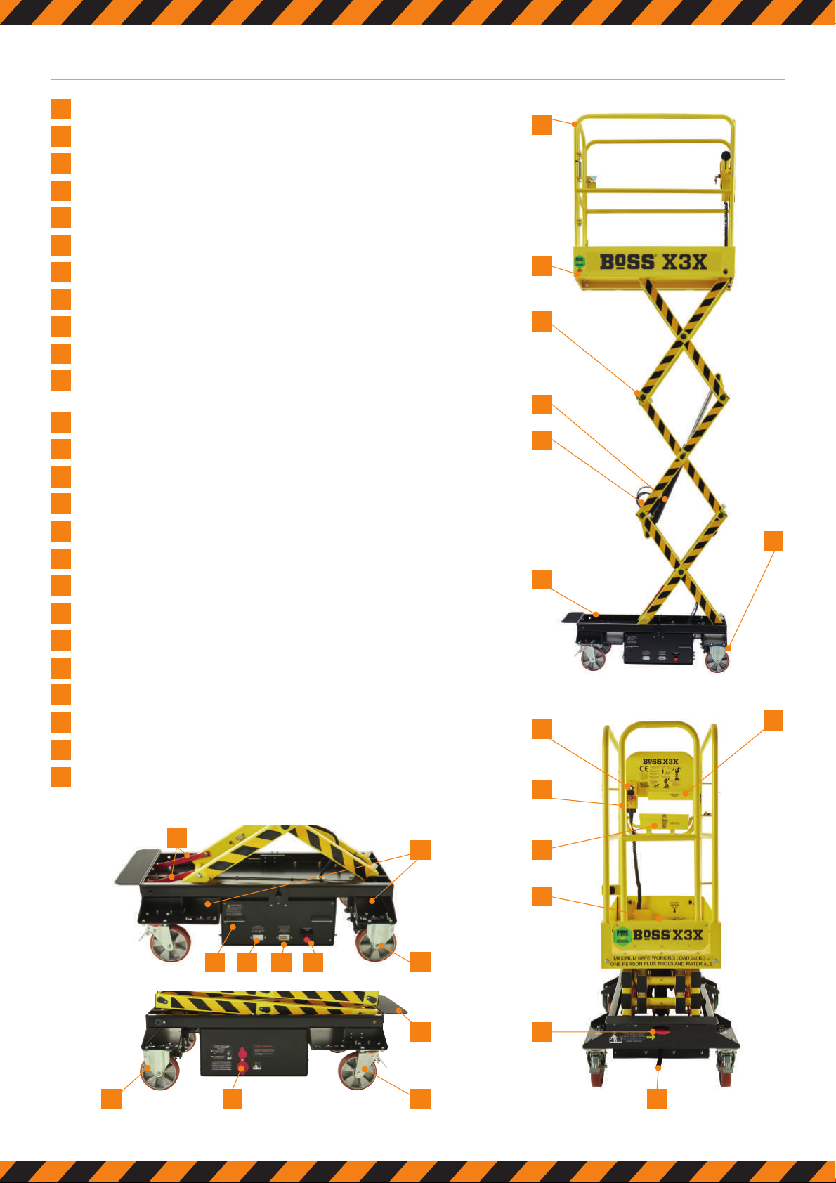
Maintenance props
BoSS X Series_Maintanence Manual Rev B 0519.indd 6 16/05/2019 14:58