Stratus SAE-MS9000X Guide
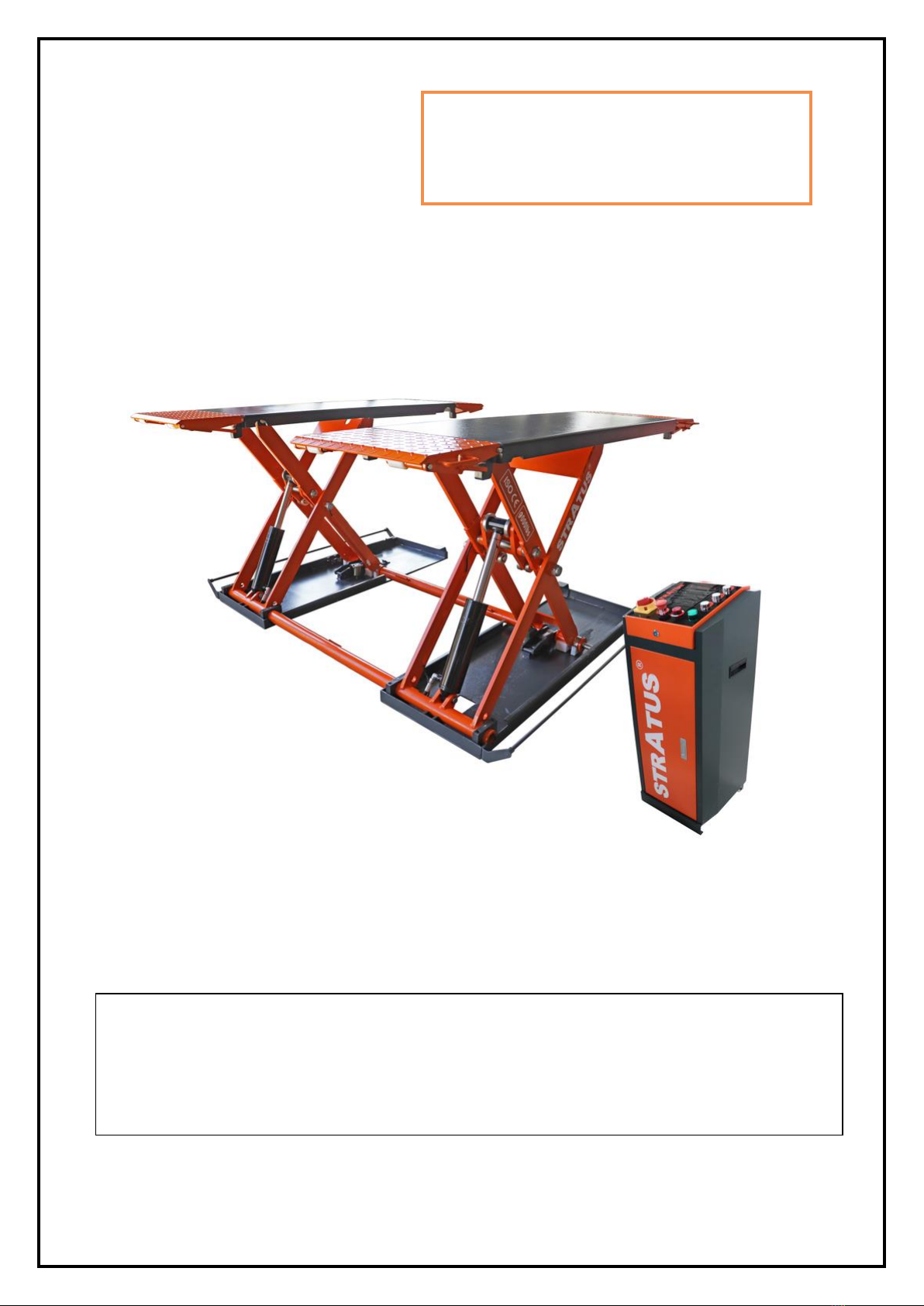
Model No. SAE-MS9000X
Mid Rise Scissor Lift
Automatic Release
Lifting Capacity 9000 lbs
Installation & Operation &
Maintenance Instructions
Important Note
1. This equipment can not be installed, operated or repaired without reading instructions.
2. Electricity must be hooked up by certified electrician.
3. Do not use this equipment beyond its rated capacity.

STRATUS Mid Rise Scissor Lift Installation & Operation & Maintenance Instructions
1
INDEX
1. Important safety instructions……………………………….….2~3
1.1 Important notices
1.2 Qualified personnel
1.3 Danger notices
1.4 Warning signs
1.5 Sound level
1.6 Training
1.7 Special reminder
2. Overview of the lift………………………………………………..3
2.1 General descriptions
2.2 Technical data
2.3 Construction of the lift
3. Installation instructions………………………………………….4~5
3.1 Preparations before installation
3.1.1 Tools and equipment needed
3.1.2 A list for parts checking
3.1.3 Ground conditions
3.2 Precautions for installation
3.3 Installation
3.4 Items to be checked after installation
4. Operation instructions……………………………………………5~8
4.1 Precautions
4.2 Descriptions of control box
4.3 Flow chart for operation
4.4 Operating instructions
4.5 Emergency lowering in case of no power
5. Trouble shooting………………….……………………………….9
6. Maintenance……………………………………………………….10
7. Annex…………………………………………………….………….11~21
Annex1. Packing list of the whole lift
Annex2. Overall diagram
Annex3. Hydraulic working system
Annex4. Diagram for pneumatic system.
Annex5. Wiring diagram
Annex6. Separate diagrams for the lift
Annex7. Spare parts list
Annex8. Size and weight requirements on vehicles

STRATUS Mid Rise Scissor Lift Installation & Operation & Maintenance Instructions
2
1. IMPORTANT SAFETY INSTRUCTIONS
1.1 Important notices
We will offer one-year's quality warranty for the whole machine,during which any quality problem will be properly solved to
the user's satisfaction. However, we will not take any responsibility for whatever bad consequence resulted from improper
installation and operation, overload running or unqualified ground condition.
This middle rise scissor lift is especially fit for tire service or other quick service around vehicles. Users must always bear in
mind that this SAE-MS9000E is specially designed for lifting cars or other vehicles, so never use it for any other purposes.
Otherwise, as well as our sales agency, will not bear any responsibility for accidents or damages of the lift.
Make sure to pay careful attention to the label of the lifting capacity attached on the lift and never try to lift cars with its weight
beyond.
Read this manual carefully before operating the machine so as to avoid economic loss or personnel casualty incurred by
wrong operation.
Without our professional advice, users are not permitted to make any modification to the control unit or whatever mechanical
unit.
1.2 Qualified personnel
1.2.1 Only these qualified staff, who have been properly trained, can operate the lift.
1.2.2 Electrical connection must be done by a competent electrician.
1.2.3 People who are not concerned are not allowed in the lifting area.
1.3 Danger notices
1.3.1 Do not install the lift on any asphalt surface.
1.3.2 Read and understand all safety warnings before operating the lift.
1.3.3 Do not leave the controls while the lift is still in motion.
1.3.4 Keep hands and feet away from any moving parts. Keep feet clear of the lift when lowering.
1.3.5 Only these properly trained personnel can operate the lift.
1.3.6 Do not wear unfit clothes such as large clothes with flounces, tires, etc., which could be caught by moving parts of the
lift.
1.3.7 To prevent evitable incidents, surrounding areas of the lift must be tidy and with nothing unconcerned.
1.3.8 The lift is simply designed to lift the entire body of vehicles, with its maximum weight within the lifting capacity.
1.3.9 Always ensure the safety locks are engaged before any attempt to work near or under the vehicle. Never remove
safety related components from the lift. Do not use if safety related components are damaged or missing.
1.3.10 Do not rock the vehicle while on the lift or remove any heavy component from vehicle that may cause excessive
weight shift.
1.3.11 Check at any time the parts of the lift to ensure the agility of moving parts and the performance of synchronization.
Ensure regular maintenance and if any abnormal occurs, stop using the lift immediately and contact our dealers for help.
1.3.12 Lower the lift to its lowest position and do remember to cut off the power source when service finishes.
1.3.13 Do not modify any parts of the lift without manufacturer’s advice.
1.3.14 If the lift is going to be left unused for a long time, users are required to:
a. Disconnect the power source;
b. Empty the oil tank;
c. Lubricate the moving parts with hydraulic oil.
Attention: For environment protection, please dispose the disused oil in a proper way.

STRATUS Mid Rise Scissor Lift Installation & Operation & Maintenance Instructions
3
1.4 Warnings (Read and understand all safety warnings before operation)
All safety warning labels are clearly depicted on the lift to ensure that the operator is aware of and avoids the dangers of
using the lift in an incorrect manner. The labels must be kept clean and they have to be replaced if detached or damaged.
Please read carefully the meaning of each label and memorize them for future operation.
1.5 Sound Level
The sound emitted from the lift should not exceed 75DB. For the sake of your health, we suggest putting a noise detector in
your working area.
1.6 Training
Only properly trained people are allowed to operate the lift. We are quite willing to provide professional training for the users
when necessary.
1.7 Special Reminder
The newly installed lift can NOT directly lift vehicle, and should be raised to the highest point then lower to the lowest point
2-3 times repeatedly without any load to bleed the air out from the hydraulic hose and cylinders to ensure the lift runs
smoothly.
1st time use the lift with load after air bleeding should follow the steps as below:
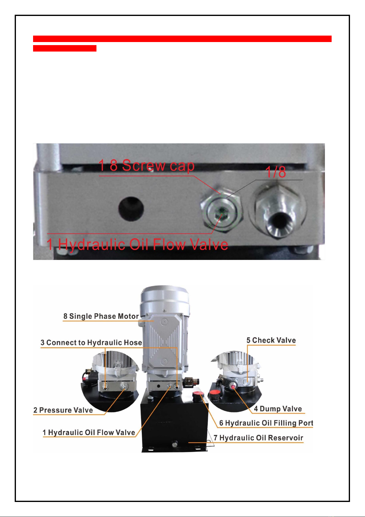
1. Loosen the screw cap of Hydraulic Oil Flow Valve and tighten the middle hexagonal screw clockwise inward to
the tightest.
2. Press the “UP” button to raise the lift with loaded vehicle to your desired height.
3. Press and hold the “DOWN” button to wait for the safety lock to be disengaged, then finely counterclockwise
adjust Hydraulic Oil Flow Valve (the middle hexagonal screw) to make the lowering speed reach 0.5inch/sec or
slower.
Note: The screw rotation must be adjusted by 1/8 or 1/16 as a scale.
STRATUS Mid Rise Scissor Lift Installation & Operation & Maintenance Instructions
4
Danger: When adjusting the flow valve, the rotation range can not be too large. Excessive adjustment range will cause the
vehicle to fall/drop rapidly.
Danger: The lift with loaded vehicle can not fall too fast. Otherwise it may cause damages to the lift or vehicle or even cause
rollover accident.
Repeat raising and lowering the lift 1-2 times to experience the speed. After confirming the lowering speed is stable, fix the
Hydraulic Oil Flow Valve nut.
Warning: The lowering speed of the lift is not fixed. The heavier the vehicle the faster the lowering speed is. The lowering
speed in winter is lower than in summer, so if you do not use the lift for a long time or use it across seasons, repeat the
above steps for adjustment.

STRATUS Mid Rise Scissor Lift Installation & Operation & Maintenance Instructions
5
**Important Information**
1 Hydraulic Oil Flow Valve: Clockwise adjustment to make the down speed faster, counterclockwise adjustment to make
the down speed slower.
2 Pressure Valve: Clockwise adjustment increases pressure to make the power unit to have more power, counterclockwise
adjustment decreases pressure to make the power unit to have less power.
4 Dump Valve: When the power is off or the scissor lift fails, manually release the safety lock first, then press the Dump
Valve and clockwise adjust it, the lift will go down. After the lift is down, press the Dump Valve and counterclockwise adjust
it to recover.
2. Overview of the lift
2.1 General descriptions
The lift is driven by an electro-hydraulic system. The gear pump delivers hydraulic oil to oil cylinders and pushes upwards
their pistons to raise the platforms. For this model, we offer two safety solutions: one with anti-surge valve in hydraulic
system to prevent sudden drop down of platform in case the oil hose broke, the other with anti-surge valve and an extra
pneumatic safety lock.
Pneumatic safety lock.
2.2 Technical data
Model
Lifting capacity
Lifting time
Lifting height
Power supply
SAE-MS9000X
9000lbs
40S
39.37inch
110V/220V, Single Phase
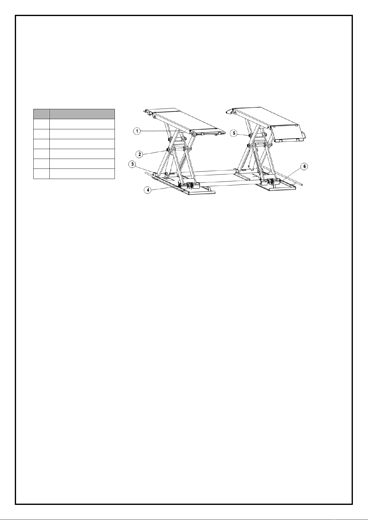
2.3 Construction of the lift
3. Installation instructions
3.1 Preparations before installation
3.1.1 Tools and equipment needed
√ Electrical drill
√ Open wrenches
√ Screw drivers
√ Adjustable spanners
STRATUS Mid Rise Scissor Lift Installation & Operation & Maintenance Instructions
6
3.1.2 List for parts checking ---Annex 1(Packing list)
Unfold the package and check if any parts missed as per Annex 1. Do not hesitate to contact us in case any parts missed,
but if you do not contact us and insist installing upon the lack of some parts, Friend as well as our dealers will not bear any
responsibility for this and will charge for any parts subsequently demanded by the buyer.
3.1.3 Ground conditions
The lift should be fixed on a smooth and solid concrete ground with its strength more than 3000psi, tolerance of flatness
less than 5mm and minimum thickness of 200mm. In addition, newly built concrete ground must undergo more than
28days’ cure and reinforcement.
3.2 Precautions for installation
3.2.2 Joints of oil hose must be firmly connected in order to avoid leakage.
3.2.3 All bolts should be firmly screwed up.
3.2.4 Do not place any vehicle on the lift in the case of trial running.
3.3 Installation
Step 1: Remove the packaging and take the mechanical and hydraulic assembly to the designated installing place.
Please do read and understand this manual thoroughly before next step.
Step 2: Connect the oil hose to the pump assembly with a proper wrench. (Make sure the hose end is clean).
Step3: Connect the wires of limit switch to the wiring terminals in the control box. Make sure to connect NO.1 wire
with NO.1 terminal, NO.2 wire with NO.2 terminal and so forth.
Step4: Link the air hose to compressed air source. (This step is only for the type with pneumatic safety lock)
Step 5: Fix the base frame. (Optional)
This FL-8803 is portable. In other word users may use it without having it placed and fixed on the ground. Nevertheless, if
you want to have it fixed, do fix it on a smooth and solid concrete surface.
Step 6: Trial testing with load. (Do not use cars for trial testing)
Load applied shall not exceed 2500KG.
This step is of particular importance for it can check if the oil hose and air hose are well connected. Connections are qualified
when there is no abnormal sound or leakage after having been tested for 2 or 3 times.

STRATUS Mid Rise Scissor Lift Installation & Operation & Maintenance Instructions
7
Start
Turn on the power switch
The lift is raised
Press the UP button
Motor drives the gear pump work
Cylinder piston drives the platform move up
Start
Turn on the power switch
The lift is lowered
3.4 Items to be checked after installation
S/N
Check items
YES
NO
1
Are two platforms on the same level?
2
Are oil hoses well connected?
3
Are electrical connections correct?
4
Do valves on the pump assembly leak?
4. Operation instructions
4.1 Precautions
4.1.1 Check all the joints of oil hose. Only when there is no leakage, the lift can start work.
4.1.2 The lift, if its safety device malfunctions, shall not be used.
4.1.3 The machine shall not lift or lower an automobile if its center of gravity is not positioned midway of the rising platforms
Otherwise, the Friend as well as our dealers will not bear any responsibility for any consequence resulted thereby.
4.1.4 Operators and other personnel concerned should stand in a safety area during lifting and lowering process.
4.1.5 When platforms rise to the desired height, switch off the power at once to prevent any wrong operation done by
unconcerned people.
4.1.6. Make sure the safety lock of the lift is engaged before start working under the vehicle and no people under the vehicle
during lifting and lowering process.
4.2 Descriptions of control box
4.3 Flow chart for operation
Press the DOWN button

STRATUS Mid Rise Scissor Lift Installation & Operation & Maintenance Instructions
8
4.4 Operation instructions
Raise the lift
1.Make sure that you have read and understood the operation manual before operation.
2.Drive and park the vehicle midway between two platforms.
3.Place the four rubber pads under the prop-points of the vehicle and ensure car’s gravity have fallen on the rubber pads.
4.Press the UP button on the control box until rubber pads have touched the prop-points of vehicle.
5. Keep on pressing the UP button to lift the vehicle a bit higher from the ground and check again if the vehicle is in a safe
position.
6. Having raised the vehicle to the required height, press the “Emergency stop” button before performing maintenance or
repair work.
Lower the lift
1. Switch on (press the “emergency stop button” until the power indicator is on).
2.Press the DOWN button to lower the lift.( For the model with pneumatic safety lock, firstly platforms of the lift will rise about
5cm which is to release the safety lock; for the model without pneumatic safety lock, platforms will go down directly.)
3.Drive away the vehicle.
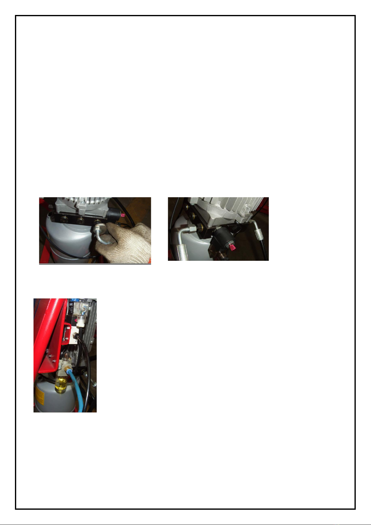
4.5 Emergency lowering in case of no power
The safety lock is not engaged:
a.
Tie up the safety teeth on both sides with rope; pull upward the rope making the safety teeth unlocked.
b.
Having the safety teeth unlocked, manually loose the core of electro-magnetic valve on the pump assembly.

STRATUS Mid Rise Scissor Lift Installation & Operation & Maintenance Instructions
9
The safety lock is engaged:
a. Screw off the fitting (opposite to the oil out-let) to connect a hand pump. (Optional)
b. Connect the hydraulic assembly with the optional hand pump. Press down the handle of the pump to raise the
platforms to have the safety teeth unlocked.
c. Tie up the safety teeth with rope and pull up the safety teeth.
d.
Use a wrench to loose the core of the electro-magnetic valve to lower the platforms.
STRATUS Mid Rise Scissor Lift Installation & Operation & Maintenance Instructions
10
5. Trouble Shooting
ATTENTION: If the trouble could not be fixed by yourself, please do not hesitate to contact us for help. We will offer our
service at the earliest time we can. By the way, your troubles will be judged and solved much faster if you could provide us
more details or pictures of the trouble.
TROUBLES
CAUSE
SOLUTION
Motor does not run and
will not raise
The wire connection is loose.
Check and make a good connection.
The motor is burnt
Replace it.
The limit switch is damaged or the wire
connection is loose.
Connect it or adjust or replace the limit
switch.
Motor runs but will not
raise
The motor run reversely.
Check the wire connection.
Overflow valve is loose or jammed.
Clean or adjust it.
The gear pump is damaged.
Replace it.
Oil level is too low.
Add oil.
The oil hose became loose or dropped off.
Tighten it.
The cushion valve became loose or jammed.
Clean or adjusts it.
Platforms go down
slowly after being raised
The oil hose leaks.
Check or replace it.
The oil cylinder is not tightened.
Replace the seal.
The single valve leaks.
Clean or replace it.
The overflow valve leaks.
Clean or replace it.
Electrical unloading valve leaks.
Clean or replace it.
Raising too slow
The oil filter is jammed.
Clean or replace it.
Oil level is too low.
Add oil.
The overflow valve is not adjusted to the right
position.
Adjust it.
The hydraulic oil is too hot (above 45°).
Change the oil.
The seal of the cylinder is abraded.
Replace the seal.
Lowering too slow
The throttle valve jammed.
Clean or replace.
The hydraulic oil is dirty.
Change the oil.
The anti-surge valve jammed.
Clean it.
The oil hose jammed.
Replace it.
STRATUS Mid Rise Scissor Lift Installation & Operation & Maintenance Instructions
11
6. Maintenance
Easy and low-cost routine maintenance can ensure the lift work normally and safely. Following are requirements for routine
maintenance. You may choose the frequency of routine maintenance by consulting your lift’s working conditions and time.
THE FOLLOWING PARTS NEED TO BE LUBRICATED
6.1. Daily checking items before operation
The user must perform daily check. Daily check of safety lock system is very important, the discovery of device failure
before action could save your time and prevent you from great loss, injury or casualty.
·Before operation, judge whether the safety lock is engaged by sound.
·C heck whether oil hose well connected and whether it leaks or not.
·C heck the electrical system.
·Check whether plug bolts firmly screwed.
·Check if safety teeth and safety block matched well or not.
6.2. Weekly checking items
·C heck the flexibility of moving parts.
·Check the working conditions of safety parts.
·Check the amount of oil left in the oil tank. Oil is enough if the platforms can be raised to highest position.
Otherwise, oil is insufficient.
·Check whether plug bolts firmly screwed.
6.3. Monthly checking items
·Check whether plug bolts firmly screwed.
·Check the tightness of the hydraulic system and screw firm the joints if it leaks.
6.4. Yearly checking items
·Empty the oil tank and check the quality of hydraulic oil.
·Wash and clean the oil filter.
If users strictly follow the above maintenance requirements, the lift will keep in a good working condition and
meanwhile accidents could be avoided to a large extent.
S/N
Description
1
Small idler wheel
2
Rotor shaft
3
U-shape block
4
Safety shaft
5
Rotor shaft of oil tank
6
Slider

STRATUS Mid Rise Scissor Lift Installation & Operation & Maintenance Instructions
12
7. ANNEX
Annex 1. Packing List of the whole lift
S/N
Name
Qty
1
Mechanical Assembly
1
2
Mobile kit
Optional
2.1
Wheel
3
2.2
Pull rod
1
3
Feet protector
2
4
Hydraulic system
1
Annex 2. Overall diagram

STRATUS Mid Rise Scissor Lift Installation & Operation & Maintenance Instructions
13
Annex 3. Diagram for pneumatic system. (Only applicable to the version with
pneumatic release mechanical lock)
Annex 4. Hydraulic working system
1. Driving cylinder
2. Assistant cylinder
3. Electrical release valve
4. Lowering throttle valve
5. Motor
6. Coupling
7. Gear pump
8. Check valve
9. Relief valve
10. Anti-surge valve
11. Trimmer valve
12. Emergent unloading valve
1. Air filter
2. Pneumatic solenoid valve
3. Pneumatic cylinder for the main platform
4. Pneumatic cylinder for the assistant platform

STRATUS Mid Rise Scissor Lift Installation & Operation & Maintenance Instructions
14
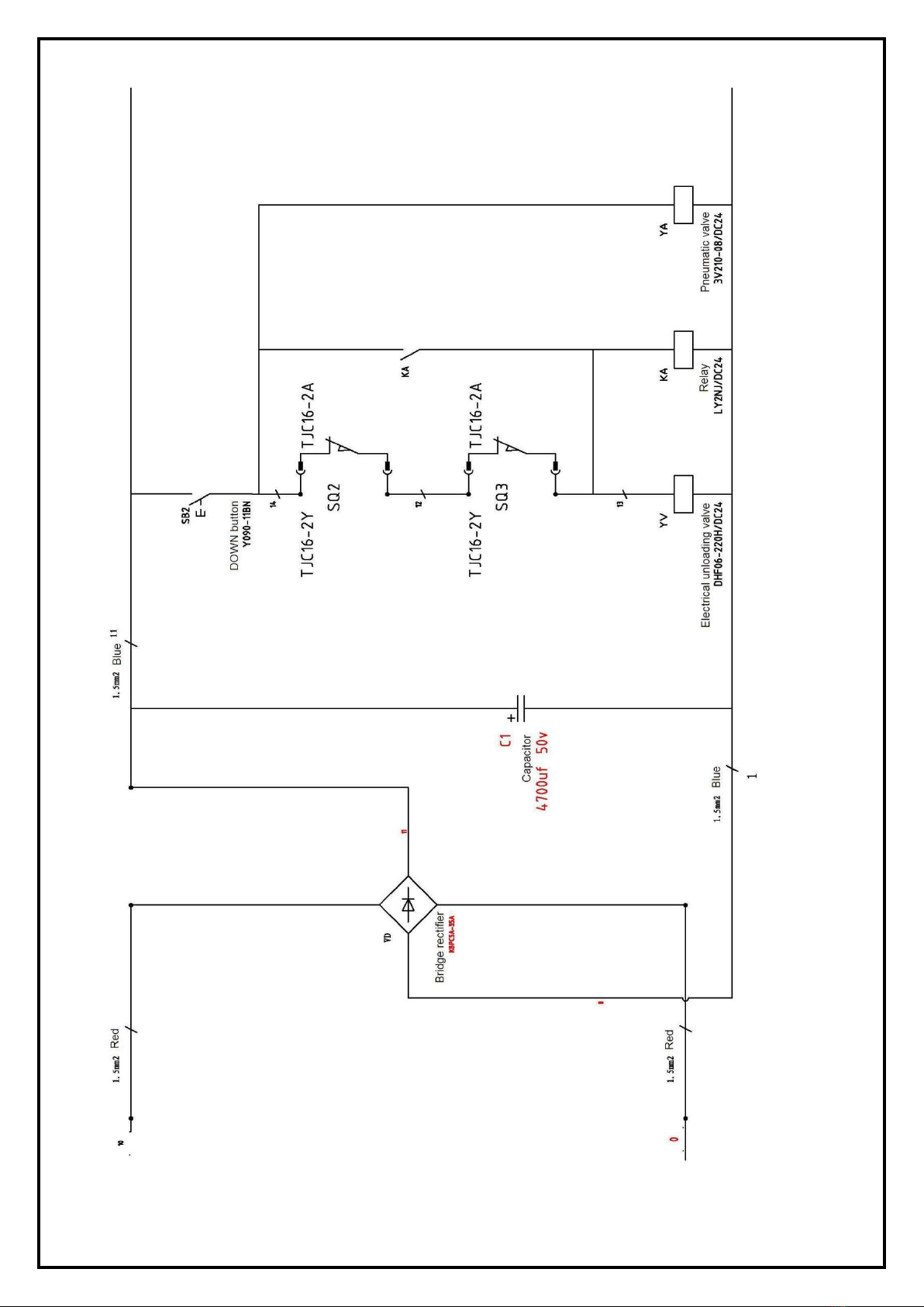
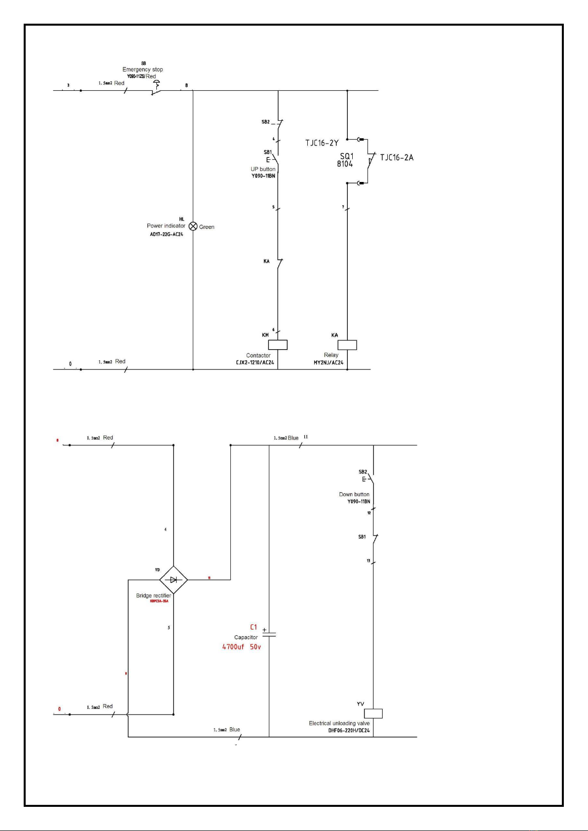
Annex 5. Wiring diagram
Wiring diagram for electrical system with common transformer
Single Phase
STRATUS Mid Rise Scissor Lift Installation & Operation & Maintenance Instructions
15

STRATUS Mid Rise Scissor Lift Installation & Operation & Maintenance Instructions
16
Inside layout of control box
STRATUS Mid Rise Scissor Lift Installation & Operation & Maintenance Instructions
17

STRATUS Mid Rise Scissor Lift Installation & Operation & Maintenance Instructions
18
Annex 6. Separate diagrams for the lift
For the pump:
For the lift
S/N
DESCRIPTION
QTY
1
MOTOR
1
2
HYDRAULIC BLOCK
1
3
OVERFLOW VALVE
1
4
FITTING
2
5
CUSHION VALVE
1
6
ABSORBING OIL PIPE
1
7
OIL FILTER
1
8
THROTTLE VALVE
1
9
OIL HOSE TIE-IN
1
10
ELECTRICAL UNLOADING VALVE
1
11
SINGLE-WAY VALVE
1
12
GEAR PUMP
1
13
OIL TANK
1
14
OIL TANK COVER
1
15
OIL BACK PIPE
1

STRATUS Mid Rise Scissor Lift Installation & Operation & Maintenance Instructions
19
S/N
Name
Qty
S/N
Name
Qty
1
Base plate(right)
1
29
Fixed clap for slider
8
2
Base plate(left)
1
30
Outer scissor arm roller shaft
8
3
Outer scissor arm
1
31
Inner scissor arm fixed roller
8
4
Inner scissor arm
1
32
Hexagon bolt
7
5
Slider for inner scissor arm(left)
2
33
Electric safety lock hook(right)
1
6
Slider for inner scissor arm(right)
2
34
Electric safety lock hook(left)
1
7
Platform(left)
1
35
U shaped block
5
8
Platform(right)
1
36
Hexagon bolt
16
9
Slider for outer scissor arm
8
37
Ramps
2
10
Power arm oil-free shaft sleeve
8
38
Ramps
2
11
Power arm shaft
2
39
Ramps long shaft
8
12
Scissor arm shaft
4
40
Snap ring for shaft A
48
13
Scissor arm shaft washer
8
41
Ramps short shaft
15
14
Power arm
2
42
Nylon wheel
16
15
Cylinder bore
2
43
Ramps support bracket
4
16
Piston rod
2
44
Limit switch
1
17
Cylinder top oil-free shaft sleeve
4
45
Guard bracket
4
18
Cylinder top shaft
2
46
Oil hose
2
19
Power arm idler pulley
4
47
Oil hose
2
20
Power arm roller
8
48
Oil ring
4
21
Power arm roller shaft
4
49
Oil ring
12
22
Power arm spacer washer
4
50
Moveable wheel bracket
2
23
Non-metallic hexagon lock nut
8
51
Moveable wheel bracket
1
24
Locking shaft for inner scissor arm
2
52
Moveable pull rod
1
25
Cylinder lower shaft
2
53
Oil-free shaft sleeve for scissor arm
8
26
Hexagon bolt
2
54
Hydraulic straight fitting
4
27
Electromagnet
2
55
Control cabinet
1
28
Hexagon bolt
24
Table of contents
Other Stratus Scissor Lift manuals

Popular Scissor Lift manuals by other brands


Skyjack
Skyjack SJ9233 RT Operation manual

Hy-Brid Lifts
Hy-Brid Lifts III Series MAINTENANCE & TROUBLESHOOTING MANUAL

GMG
GMG 1230i Operator's manual

Oshkosh Corporation
Oshkosh Corporation JLG 530LRT Operation and safety manual

Jema Autolifte
Jema Autolifte JA2800S Installation, operation and maintenance manual

Upright
Upright MX19 Operator's manual