Dannmar DLR-6 User manual

1645 Lemonwood Dr.
Santa Paula, CA, 93060 USA
Telephone: (877) 432-6627
Dannmar.com
Low-Rise Scissor Lift
Installation and Operation Manual
Manual P/N 5900254 — Manual Revision A — September 2020
Models:
• DLR-6
• DLR-6P
DLR-6P shown.
⚠
DANGER
Read the
entire
contents of this manual
before
using this
product. Failure to follow the instructions and safety precautions in
this manual can result in serious injury or death. Make sure all other
operators also read this manual. Keep the manual near the product
for future reference.
By proceeding with setup and operation,
you agree that you fully understand the contents of this
manual and assume full responsibility for product use
.

Manual. DLR-6/6P Low-Rise Scissor Lift, Installation and Operation Manual, Manual Part Number 5900254,
Manual Revision A, released September 2020.
Copyright. Copyright © 2020 by BendPak Inc. All rights reserved. You may make copies of this document if you
agree that: you will give full attribution to BendPak Inc., you will not make changes to the content, you do not gain
any rights to this content, and you will not use the copies for commercial purposes.
Trademarks. Dannmar and the Dannmar logo are registered trademarks of BendPak Inc. All other company,
product, and service names are used for identification only. All trademarks and registered trademarks mentioned
in this manual are the property of their respective owners.
Limitations. Every effort has been made to ensure complete and accurate instructions are included in this
manual. However, product updates, revisions, and/or changes may have occurred since this manual was
published. BendPak reserves the right to change any information in this manual without incurring any obligation for
equipment previously or subsequently sold. BendPak is not responsible for typographical errors in this manual.
Warranty. The Dannmar warranty is more than a commitment to you: it is also a commitment to the value of
your new product. Contact your nearest Dannmar dealer or visit the Dannmar website.
Safety.Your product was designed and manufactured with safety in mind. However, your safety also depends
on proper training and thoughtful operation. Do not install, operate, maintain, or repair the unit without reading and
understanding this manual and the labels on the unit;
do not use your Lift unless you can do so safely!
Owner Responsibility. In order to ensure operator safety and maintain your product properly, it is the
responsibility of the product owner to read and follow these instructions:
• Follow all setup, operation, and maintenance instructions.
• Make sure product setup and use conforms to all applicable local, state, and federal codes, rules, and
regulations, such as state and federal OSHA regulations and electrical codes.
• Read and follow all safety instructions. Keep them readily available for operators.
• Make sure all operators are properly trained, know how to safely operate the unit, and are properly supervised.
• Do not operate the product until you are certain all parts are in place and operating correctly.
• Carefully inspect the product on a regular basis and perform all maintenance as specified.
• Service and maintain the unit only with approved replacement parts.
• Keep all instructions permanently with the product and make sure all labels are clean and visible.
•Only use the Lift if it can be used safely!
Unit Information.
Enter the Model Number, Serial
Number
, and the Date of Manufacture from the label on
your unit
. This information is required for part or
warranty issu
es.
Model:
Serial:
Date of Manufacture
:

DLR-6/6P Low-Rise Scissor Lifts 3P/N 5900254 — Rev. A — September 2020
Table of Contents
Introduction 3 Operation 26
Shipping Information 3 Maintenance 29
Safety Considerations 4 Troubleshooting 30
Components 5 Wiring Diagram 31
Specifications 6 Labels 32
Installation Checklist 7 Parts Diagrams 34
Installation 8 ALI Store 39
Introduction
This Manual describes the following Dannmar Lifts:
•DLR-6. Low-rise, frame-engaging scissor Lift that supports Vehicles up to 6,000 lbs (2,722 kg).
•DLR-6P. Low-rise, portable, frame-engaging scissor Lift that supports Vehicles up to 6,000 lbs
(2,722 kg).
This manual is
mandatory reading for all DLR-6/6P users
, including anyone who sets up,
operates, maintains, or repairs them.
Shipping Information
Your equipment was carefully checked before shipping. Nevertheless, you should thoroughly inspect
the shipment
before
you sign to acknowledge that you received it.
When you sign the bill of lading, it tells the carrier that the items on the invoice were received in good
condition.
Do not sign the bill of lading until
after
you have inspected the shipment.
If any of the
items listed on the bill of lading are missing or damaged, do not accept the shipment until the carrier
makes a notation on the bill of lading that lists the missing and/or damaged goods.
If you discover missing or damaged goods
after
you receive the shipment and have signed the bill of
lading, notify the carrier at once and request the carrier to make an inspection. If the carrier will not
make an inspection, prepare a signed statement to the effect that you have notified the carrier (on a
specific date) and that the carrier has failed to comply with your request.
It is difficult to collect for loss or damage after you have given the carrier a signed bill of lading. If this
happens to you, file a claim with the carrier promptly. Support your claim with copies of the bill of
lading, freight bill, invoice, and photographs. Our willingness to assist in helping you process your claim
does not make us responsible for collection of claims or replacement of lost or damaged materials.

DLR-6/6P Low-Rise Scissor Lifts 4P/N 5900254 — Rev. A — September 2020
Safety Considerations
Read this entire manual carefully before using your new product.
Do not set up or
use the product until you are familiar with all operating instructions and warnings. Do not allow anyone
else to operate the product until they are also familiar with all operating instructions and warnings.
General Safety Information
•The product is a low-rise scissor Lift. Use it only for its intended purpose. Do not make any
modifications to the product.
•The product
must
only be operated by authorized, trained, properly supervised personnel.
•When the Lift is being used, only the Operator may be within 30 feet of the unit.
•Do not use the product while tired or under the influence of drugs, alcohol, or medication.
•Keep loads centered and balanced on the Platforms.
•When the product is in use, keep all body parts away from it.
•Make sure all Operators study and understand the Installation and Operation Manual. Keep the
Manual near the device at all times.
•Do not use the product in the presence of cigarette smoke, dust, or flammable liquids or gases.
Use the product indoors in a well-ventilated area.
•Do not make any modifications to the product; this voids the warranty and increases the chances
of injury or property damage.
Do not modify or override safety features
.
•Make a visual inspection of the product before using it each time. Check for damage or missing
parts. Do not use the product if you find any issues.
•Make a thorough inspection of the product at least once a year. Replace any damaged or severely
worn parts, decals, or warning labels.
Symbols
Following are the symbols that may be used in this manual:
⚠DANGER Calls attention to an immediate hazard that will result in injury or death.
⚠WARNING Calls attention to a hazard or unsafe practice that could result in injury or death.
⚠CAUTION Calls attention to a hazard or unsafe practice that could result in minor personal
injury, product, or property damage.
NOTICE Calls attention to a situation that, if not avoided, could result in product or property
damage.
Tip Calls attention to information that can help you use your product better.
Liability Information
BendPak Inc. assumes no liability for damages resulting from:
• Use of the product for purposes other than those described in this manual.
• Modifications to the equipment without prior, written permission from BendPak Inc.
•Injury or death caused by modifying, disabling, overriding, or removing safety features.
• Damage to the equipment from external influences.
• Incorrect operation of the equipment.

DLR-6/6P Low-Rise Scissor Lifts 5P/N 5900254 — Rev. A — September 2020
Components
Lift components include:
•Power Unit. Provides Hydraulic Fluid to the Hydraulic Cylinders, which raises the Platforms.
•Platforms. Flat steel plates that raise and lower. The Lift Pads, which sit on the Platforms, make
contact with the underside of the Vehicle.
•Power Unit Stand. DLR-6 only. Holds the Power Unit. Bolts to the ground.
•Portable Stand. DLR-6P only. Holds the Power Unit. Freestanding, moveable.
•Tow Cart. DLR-6P only. Used to move the Lift to a different location.
•Fixed Ramps. Allows Vehicles to drive on to and off of the Platforms.
•Hinged Ramps. Allows Vehicles to drive on to and off of the Platforms.
•Base. The bottom of the Lift. Has the holes for the Anchor Bolts for the DLR-6.
•Hydraulic Cylinder. Pushes the Platforms up to raise a Vehicle, down to lower a Vehicle.
•Hydraulic Hose. Moves the Hydraulic Fluid from the Power Unit to the Hydraulic Cylinder.
•Safety Locks. Hold the Platforms up, once
engaged
. Always leave the Lift either engaged on a
Safety Lock or lowered to the ground.
•Lift Pads. Rubber blocks that make contact with the manufacturer-recommended Lifting Points.
•Wheel Assemblies. DLR-6P only. Raises the Hinged Ramp end of the Lift off the ground,
allowing the Lift to move to a different location. Not shown.

DLR-6/6P Low-Rise Scissor Lifts 6P/N 5900254 — Rev. A — September 2020
Specifications
Model DLR-6 DLR-6P
Lifting capacity 6,000 lbs. / 2,722 kg
Lift style Fixed Portable
ALift height w/lift pad 27.5" / 699 mm
BLift height, platform 26" / 660 mm
CPlatform length 53" / 1,346 mm
DLowered height 4" / 102 mm
EOverall width 70.5" / 1,791 mm
FOverall length 82" / 2,083 mm
Sound, during operation <70 dB
Lifting time ~35 seconds
Power Unit 115 VAC*, 50/60 Hz, 1 Ph
*Power Unit comes configured for 115 VAC; is reconfigurable to 230 VAC.
Specifications subject to change without notice.

DLR-6/6P Low-Rise Scissor Lifts 7P/N 5900254 — Rev. A — September 2020
Installation Checklist
Following are the steps needed to install your Lift. Perform them in the order shown.
☐1. Review the installation Safety Rules.
☐2. Make sure you have the necessary Tools.
☐3. Select the Installation Site.
☐4. Understand Longitudinal Shift.
☐5. Check clearances.
☐6. Unpack and locate the Lift.
☐7. Assemble the Portable Stand (DLR-6
P
only).
☐8. Attach the Power Unit to the Portable Stand (DLR-6
P
only).
☐9. Assemble the Tow Cart (DLR-6
P
only).
☐10. Raise the Platforms Off the Base (DLR-6 only).
☐11. About Embedment (DLR-6 only).
☐12. Anchor the Bases (DLR-6 only).
☐13. Anchor the Power Unit Stand (DLR-6 only).
☐14. Install the Wheels (DLR-6
P
only).
☐15. Understand Hydraulic Fluid Contamination.
☐16. Connect the Hydraulic Hose.
☐17. Add Hydraulic Fluid.
☐18. Reconfigure the Power Unit to 230 VAC Power (optional).
☐19. Connect to Power.
☐20. Test the Lift.
☐21. Review the Final Checklist.

DLR-6/6P Low-Rise Scissor Lifts 8P/N 5900254 — Rev. A — September 2020
Installation
This section describes how to install your DLR-6/6P. Perform the steps in the order listed.
⚠DANGER Be very careful when setting up, operating, maintaining, or repairing this equipment;
failure to do so could result in property damage, product damage, injury, or (in very
rare cases) death. Make sure only authorized personnel operate this equipment. All
repairs must be performed by an authorized technician. Do not make modifications
to the unit; this voids the warranty and increases the chances of injury or property
damage. Make sure to read and follow the instructions on the labels on the unit.
Some installation steps are the same for both Lift models, but some are different.
⚠WARNING
Only use the factory-supplied parts that came with your Lift
. If you use
parts from a different source, you void your warranty and compromise the safety of
everyone who installs or uses the Lift. If you are missing parts, visit
dannmar.com/support or call (877) 432-6627.
Safety Rules
When installing the Lift, your safety depends on proper training and thoughtful operation.
⚠WARNING Do not install this equipment unless you have automotive Lift installation training.
Always use proper tools, such as a Forklift or Shop Crane, to move heavy
components. Do not install this equipment without reading and understanding this
Manual and the safety labels on the unit.
We recommend referring to the ANSI/ALI ALIS Standard (R2015) Safety Requirements for Installation
and Service for more information about safely installing, using, and servicing your Lift.
Only trained, supervised personnel should be involved in installing this equipment.
Pay attention at
all times.
Use appropriate tools and equipment. Stay clear of moving parts.
⚠WARNING You
must
wear OSHA-approved (publication 3151) Personal Protective Equipment
at all times when installing the Lift. Leather gloves, steel-toed work boots, eye
protection, back belts, and hearing protection
are mandatory
.
Tools
You may need some or all of the following tools:
•Hammer, mallet, crowbar, or pry bar
•Hex key and wrench set, metric and SAE
•Screwdriver set, slot and Phillips
•Level, tape measure
•Adjustable crescent wrench
•Utility knife, tin or sheet metal snips
•Screwdriver set, slot and Phillips
•Forklift or Shop Crane
•Rotary Hammer Drill, Masonry Bits

DLR-6/6P Low-Rise Scissor Lifts 9P/N 5900254 — Rev. A — September 2020
Select a Site
Keep the following in mind when selecting a site for your Lift:
•Enough space. Make sure there is adequate space on all sides, plus enough space
above
for
the Vehicles you will be raising. Do not install the Lift under low-hanging obstructions. See Check
Clearancesfor more information.
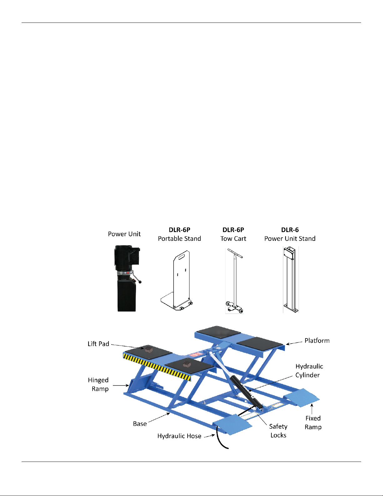
•Power Unit Location. The DLR-6 Power Unit Stand can be installed on either side of the Lift,
close enough for the Hydraulic Hose to reach. The DLR-6PPower Unit is installed on a Portable
Stand, which can be easily moved to the desired location on either side of the Lift within reach of
the Hydraulic Hose. Operators
must
always have a full, unobstructed view of the Lift.
•Hose Cover. The DLR-6 comes with a Hose Cover that you can anchor to the ground; it is
54 in / 1,372 mm long. If you plan to use the Hose Cover, make sure to leave enough room
between the Power Unit and the Lift.
•Operator. The operator
must
have a full, unobstructed view of the Lift and the Vehicle on it when
raising and lowering Vehicles.
•Longitudinal Shift. When you raise the Lift, the geometry of the scissor arms moves the
Platforms up at an angle. The amount of longitudinal shift for the DLR-6/6P is approximately 14
inches. Refer to About Longitudinal Shift for more information.
•Check for overhead obstructions. The site must be free of overhead obstructions.
•Floor. Do not install or use this Lift on any asphalt surface or any surface other than concrete.
•Concrete specifications. Do not install the Lift on or within 6 in / 152 mm of expansion seams
or cracked or defective concrete. Make sure the concrete is at least 4.25 inches thick, 3,000 psi,
and cured for at least 28 days (if newly poured). Make sure the floor is defect-free, dry, and level.
⚠WARNING Do not install the Lift on a surface with 3° of slope or more. A 3° degree or greater
slope makes the Lift less secure, possibly causing Vehicles to fall, which could lead
to property damage, personal injury, or even death.
•Power. You will need a 115 VAC or a 230 VAC power source near the Power Unit. The Power
Unit ships configured for 115 VAC, but it can be reconfigured to operate on 230 VAC Power. See
Reconfigure the Power Unit to 230 VAC for more information.
•Operating temperature. The Lift is designed to be used between temperatures of 41º to 104ºF
(5º to 40ºC).
•Outdoor installation. The Lift
cannot
be installed outside. It is for indoor use only. If you have
the DLR-6P, you can move it outside and use it outside temporarily; make sure to keep it
completely moisture free while it is outside.
•Second floor installs. Do not install the Lift on a second floor or elevated floor without first
consulting the building architect and getting their permission.
•Dress properly. Always wear protective gear when installing the Lift. Leather gloves, steel-toed
work boots, eye protection, back belts, and hearing protection
are mandatory
. Do
not
wear
loose clothing or jewelry; contain long hair; keep hair, clothing, and gloves away from moving parts.
⚠WARNING You
must
wear OSHA-approved (publication 3151) Personal Protective Equipment
at all times when installing
the Lift.

DLR-6/6P Low-Rise Scissor Lifts 10 P/N 5900254 — Rev. A — September 2020
About Longitudinal Shift
When you raise a Vehicle on the DLR-6/6P, the Vehicle goes up; it does
not
go straight up.
Instead, the geometry of the scissor arms moves the Platforms up at an angle (called longitudinal shift),
towards the Hinged Ramp end of the Lift. The amount of longitudinal shift for the DLR-6 and the
DLR-6P is approximately 14 in / 356 mm.
Longitudinal shift is always in the same direction, towards the Hinged Ramp end of the Lift, no matter
which way the Vehicle is facing.
Vehicle not shown. Not necessarily to scale. Not all components shown.

DLR-6/6P Low-Rise Scissor Lifts 11 P/N 5900254 — Rev. A — September 2020
Check Clearances
For safety purposes, a certain amount of clear space around the Lift is
required
.
Additional space on Hinged Ramp side for longitudinal shift. Not necessarily to scale. Not all
components shown.
Unpack and Locate the Lift
Using an appropriate lifting device (Shop Crane or Forklift, for example), move the Lift off of the bottom
of the shipping container and to its permanent location (in the case of the DLR-6) or its starting location
(in the case of the DLR-6P).
⚠CAUTION Use caution when taking the Lift out of its shipping container. You do not want to
damage the unit, misplace the components, or get hurt.

DLR-6/6P Low-Rise Scissor Lifts 12 P/N 5900254 — Rev. A — September 2020
Assemble the Portable Stand (DLR-6P only)
The DLR-6P comes with a Portable Stand to hold the supplied Power Unit.
Assemble the Portable Stand as shown below; securely tighten all connections.
Attach the Power Unit to the Portable Stand (DLR-6P only)
Once you have assembled the Portable Stand, attach the Power Unit.
Attach the Power Unit using the included M8 x 25 Bolts, M10 Washers, and M8 Nuts.
Important: Do not connect the Power Unit to the Hydraulic System or power source at this point
of the installation; those connections will be made later.
Not drawn to scale. Not all components shown.

DLR-6/6P Low-Rise Scissor Lifts 13 P/N 5900254 — Rev. A — September 2020
Assemble the Tow Cart (DLR-6P only)
The Tow Cart, which is used only with the DLR-6P, lets you move the Lift to other locations.
The following drawing shows how to set up the Tow Cart.
Raise the Platforms Off the Base
You need to raise the Platforms off the Base to access two of the three Anchor Bolt holes
(Anchoring for DLR-6 only).
Be sure to leave the Lift engaged on a Safety Lock when you
raise it.
⚠WARNING We strongly recommend using
at least two people
to lift the Platforms off their
Bases: one person to hold down the Base and one person to operate the Forklift or
Shop Crane to raise the Platforms.
Use care when raising the Platforms off
the Base
.
To lift the Platforms off the Base:
1. Use a Forklift or Shop Crane to raise the Platform off of its Base.
Make sure to hold down the Base while you raise the Platform.
Tip Once the Platform and Base are separated by more than half an inch (~13 mm), you
can put industrial slings (straps) around each end to continue raising the Platform off
the Base.
2. When the Platform gets above the top Safety Lock, lower it back down onto the top Safety Lock.
Do
not
raise the Platform a random distance; leave it on the top Safety Lock.
⚠WARNING Do not continue with the installation without first confirming that the Lift is securely
engaged on a Safety Lock.

DLR-6/6P Low-Rise Scissor Lifts 14 P/N 5900254 — Rev. A — September 2020
About Embedment
Anchor Bolts (also called Wedge Anchors) get their holding strength from how far down into the Hole
the Anchor Bolt is installed (called embedment) and how forcefully the Expansion Sleeve presses into
the Concrete (based on how much torque is applied).
To get enough embedment, you have to understand Effective Embedment, which means the location
in the Hole where the Expansion Sleeve presses into the Concrete. This is where the Anchor Bolts
create holding strength; the further down into the Hole, the greater the holding strength.
(The technical definition of Effective Embedment is the distance from the surface of the base material
to the deepest point at which the load is transferred to the base material; the “base material” in our
case being the Concrete into which the Anchor Bolts are being installed.)
Some people confuse Effective Embedment with Nominal Embedment, which is how far down into the
Hole the bottom of the Anchor Bolt is.
As shown below, the two are not the same. Nominal Embedment is
not
where the load is transferred
to the base material, Effective Embedment is.
Not necessarily to scale.
The Anchor Bolts shipped with your product may have letters stamped into their tops, indicating their
length.
For example:
•4.75 in / 120 mm Anchor Bolts are stamped with a G.
•6.3 in / 160 mm Anchor Bolts are stamped with a J.

DLR-6/6P Low-Rise Scissor Lifts 15 P/N 5900254 — Rev. A — September 2020
Anchor the Bases (DLR-6 only)
The Lift has three holes in the Base for anchoring it. Anchoring provides stability for the Lift.
Give a lot of thought to where you want the DLR-6
before
anchoring it:
once the Lift is
anchored, it is extremely difficult to move
.
Concrete specifications are:
•Depth: 4.25 in (108 mm) thick
•PSI: 3,000 PSI, minimum
•Cured: 28 days, minimum
Anchor Bolt specifications are:
•Length: 4.75 inches
•Diameter: ¾ inch
•Effective embedment: 2.75 inches, minimum
•Anchor torque: 85 – 95 pound feet
(do not torque less than 80 or more than 105)
Anchor Bolt holes must be at least 6 in / 152 mm away from expansion seams or cracked Concrete.
⚠WARNING
Only use the factory-supplied parts that came with your Lift
. If you use
parts from a different source, you void your warranty and compromise the safety of
everyone who installs or uses the Lift.
To anchor the Lift:
1. Make sure you are wearing OSHA-approved (publication 3151) Personal Protective Equipment:
leather gloves, steel-toed work boots, back belts, hearing protection, and ANSI-approved eye
protection (safety glasses, face shield, or goggles).
2. Make sure the Lift is in the desired location.
3. If it is not already, raise the Lift as high as it will go, then engage it on the top Safety Lock.
Refer to Raising a Vehicle for lifting instructions.
4. Using the holes in the Base as guides, drill each hole 4 in / 101 mm deep.

DLR-6/6P Low-Rise Scissor Lifts 16 P/N 5900254 — Rev. A — September 2020
Note: If you prefer, you can mark the Anchor Bolt hole locations, move the unit out of the way,
drill the holes, and then move the unit back into position.
When drilling, go in straight; do not let the drill wobble.
Use a carbide bit (conforming to ANSI B212.15).
The diameter of the drill bit
must
be the same as the
diameter of the Anchor Bolt.
5. Use a wire brush and a vacuum to
thoroughly
clean each hole.
You can also use a hand pump or compressed air. Make
sure to thoroughly clean the holes.
Do
not
ream the hole. Do
not
make the hole any wider
than the drill bit made it.
6. Make sure the Washer and Nut are in place and flush with the top of the Bolt, then insert the
Anchor Bolt into the hole.
7. Hammer or mallet the Anchor Bolt the rest of the way down into the hole.
Stop hammering when the Washer is snug against the Base.
Use a hammer or mallet to get the Expansion Sleeve
through the Base and down into the hole.
Even using a hammer or mallet, the Anchor Bolt should
only go into the hole part of the way; this is normal. If the
Anchor Bolt goes all the way in with little or no resistance,
the hole is too wide.
Once past the hole in the Base, the Anchor Bolt eventually
stops going down into the hole as the Expansion Sleeve
contacts the sides of the hole; this is normal.
8. Torque each Nut
clockwise
to the recommended installation torque, 85 – 95 pound feet (do not
torque less than 80 or more than 105), using a Torque Wrench.
Wrenching the Nut forces the wedge up, pushing out the
Expansion Sleeve and pressing it tightly against the
Concrete.
Important: Do
not
use an impact wrench to torque
the Anchor Bolts.

DLR-6/6P Low-Rise Scissor Lifts 17 P/N 5900254 — Rev. A — September 2020
Anchor the Power Unit Stand (DLR-6 only)
The DLR-6 comes with a Power Unit Stand to hold the supplied Power Unit; it can be on either side of
the Lift. The Power Unit Stand
must
be anchored.
Not necessarily to scale. Not all components shown.
To anchor the Power Unit Stand:
1. Select an appropriate site for the Power Unit Stand.
2. Locate the Power Unit Stand and two Anchor Bolts (¾" wide, 4 ¾" deep, same size as the Anchor
Bolts holding down the Lift).
3. Follow the anchoring instructions from the previous procedure to anchor the Power Unit Stand.
See Anchor the Bases for more information.
4. Once the Power Unit Stand is anchored, attach the Power Unit to it using the supplied M8 x 20
Bolts, M10 Washers, and M8 Nuts.
⚠CAUTION The Power Unit is heavy and awkward; we recommend having at least two people
work together to attach the Power Unit to the Power Unit Stand.
5. Use an appropriate tool to securely tighten the connections.

DLR-6/6P Low-Rise Scissor Lifts 18 P/N 5900254 — Rev. A — September 2020
Install the Wheels (DLR-6P only)
The DLR-6P comes with two Wheel Assemblies; they come assembled, but they must be installed on
top of the Wheel Brackets, which are located next to the Hinged Ramps.
Not necessarily to scale. Not all components shown.
To install the two DLR-6P Wheels:
1. Locate the two Wheel Assemblies and the eight Bolts/Split Washers/Nuts.
2. Use a lifting device (such as a jack) to raise the Hinged Ramp end of the Lift up off the ground
approximately 6 in / 152 mm
and hold it up
.
3. Put one of the Bolts into place through a Hole in the Wheel Bracket
from underneath
.
4. Put a Wheel Assembly into place on top of the Wheel Bracket, then put a Split Washer and Nut
onto the Bolt Threads.
5. Put the other three Bolts/Split Washers/Nuts into place and finger tighten the Nuts.
6. Repeat Steps 3 through 5 for the other Wheel Assembly.
7. Use an appropriate tool to securely tighten all of the Nuts and then lower the Hinged Ramp end of
the Lift back down to the ground.

DLR-6/6P Low-Rise Scissor Lifts 19 P/N 5900254 — Rev. A — September 2020
Hydraulic Fluid Contamination
Hydraulic Fluid contamination poses a
serious
issue for your Lift; contaminants such as water, dirt, or
other debris can get into the Hydraulic Hoses and Fittings of your Lift, eventually getting into the
Hydraulic Fluid. Once debris is in the system, you could experience issues such as one Platform
lowering faster than the other, internal and external Hydraulic Fluid leaks, slow operation, and so on.
Your Lift is shipped from the factory with clean components; however, we
strongly
recommend that
you give the hydraulic components an extra cleaning. Even a small grain of debris introduced into the
Hydraulic System is enough to make the Lift unusable. It is better (and less costly) to take these extra
steps now, so that you do not need to take your Lift out of service later to fix issues that could have
been prevented.
What you need to do
When you get to the procedure describing how to connect the Hydraulic Hose, make sure to take a
survey of the Hydraulic components that come with your Lift
prior
to making connections. There are
several ways to clean the Hydraulic Hoses and Fittings:
•Use an air compressor to blow out contaminants. Clean, dry air is preferred. Keep in mind that the
contaminants are going to be coming out the other end, so be prepared for that.
•For Hoses with ends not secured with Fittings, use a projectile cleaning system that shoots
expandable cleaning “pellets” through the Hydraulic Hoses to clean them all the way through.
HydraCheck, Eaton, and Ultra Clean make these types of systems.
•For Hydraulic Hose ends and Fittings that are not too long, soak part of a rag in the same
Hydraulic Fluid you will be putting in the reservoir, then use the rag to clean out the Fittings and the
ends of the Hydraulic Hoses. Do
not
use water or other cleaning fluids, as they should never be
mixed with Hydraulic Fluid.
Some additional steps that will help keep your Hydraulic System clean:
•Always use clean equipment. If you use a dirty bucket or funnel to transfer the Hydraulic Fluid
into the Hydraulic Fluid Reservoir, the contaminants will likely be introduced into the Fluid. When
using cleaning rags, use a lint-free rag.
•Proper Storage. Keep the Hydraulic Fluid sealed in its container until ready for use; store the
fluid in a clean, dry, and cool area.
•Cover the Hoses and Fittings. Before installation, do not leave the ends of the Fittings
exposed; the same applies for Hydraulic Hoses. As a general rule, keep the Hydraulic Hoses and
Fittings capped and kept in a clean area until ready for use.
•Filter the new Hydraulic Fluid. Just because it is new does not necessarily mean it is clean.
Use an offline filtration cart or kidney loop system to make sure the Hydraulic Fluid is clean
before
being transferred into the Hydraulic Fluid Reservoir.
•Avoid mixing different types of Hydraulic Fluid. If Hydraulic Fluid needs to be replaced,
make sure to flush the Hydraulic System of the old Hydraulic Fluid before you add the replacement
fluid; do not mix the two together.
•Remove old thread seal tape. Some fittings are shipped with temporary plugs secured with
thread seal tape, so make sure to thoroughly remove the thread seal tape
before
attaching an
NPT Fitting; this prevents pieces of the tape from being pushed into the Hydraulic System. If NPT
Fittings on the Hydraulic Cylinders need to be removed or replaced, use a liquid thread sealant.
•Flush out the Hydraulic System. Drain the Hydraulic System of the current Hydraulic Fluid,
then cycle the Lift a few times using low-viscosity flushing liquid to push out debris trapped in the
system; make sure the flushing liquid is compatible with the working fluid.

DLR-6/6P Low-Rise Scissor Lifts 20 P/N 5900254 — Rev. A — September 2020
Connect the Hydraulic Hose
The Hydraulic Hose connects the Power Unit to the Hydraulic Cylinder on the Lift. Connecting the
Hydraulic Hose is slightly different for each model, those procedures are described here.
The following drawing shows the Hydraulic connections for the DLR-6.
Drawing not to scale. Some components not shown.
The following drawing shows the Hydraulic connections for the DLR-6
P
.
Drawing not to scale. Some components not shown.
This manual suits for next models
1
Table of contents
Other Dannmar Scissor Lift manuals
Popular Scissor Lift manuals by other brands

Peak
Peak AMGO PX12 Installation and service manual

NHT
NHT YCJ-3000B user manual

Custom Equipment
Custom Equipment Hy-Brid Lifts III Series MAINTENANCE & TROUBLESHOOTING MANUAL

DINGLI
DINGLI JCPT2223RT operators manual with maintenance information

B-TEC
B-TEC Carry Operating Manual and Test Log Book

LINCOS
LINCOS STD-5335A Use and maintenance manual