West Mountain Radio N8XJK User manual

www.westmountainradio.com
1020 Spring City Drive
Waukesha, WI 53186
262-522-6503
©2019 West Mountain Radio, All rights reserved. All trademarks are
the property of their respective owners.
N8XJK Super Booster


1
West Mountain Radio Operating Manual
INTRODUCTION
Thank you for choosing the N8XJK Super Booster from West Mountain Radio and
congratulations on nding the solution to your low voltage problems for mobile,
portable, or emergency power operation!
This product is designed to boost your battery voltage to a level optimum for
transmit allowing the maximum use of a battery’s energy. There is an RF sensor
that may optionally be used to detect when you are transmitting so the booster is
only used when needed. The booster also has connections that may be used to
connect multiple units in parallel for increased current ow. The minimum input
voltage and the Booster output voltage are adjustable.
Many radios on the market today do not tolerate low voltage conditions. This
Booster was designed to supply a constant voltage to the radio regardless of
the battery voltage. The Booster is a switching power supply that regulates the
output voltage to the attached radio. The increased voltage prevents distortion
commonly seen on modern mobile radios. It also maintains transmit power and
allows longer operation from a battery.
The Booster was designed so that the boosted voltage is added to the battery
voltage. This means that only the dierence between the input and output
voltage is converted by the internal Switch Mode Power Supply. Because of this
conguration most of the losses only apply to the boosted voltage. This means
that real world eciency is above 90%.
The unique design of the Booster allows battery voltage to be present at the
output of the supply even when the supply is disabled or in stand by mode. No
transfer relays are required. The Booster does not boost voltage when battery
voltage is above the regulator set point. If there is enough voltage it does not do
anything.
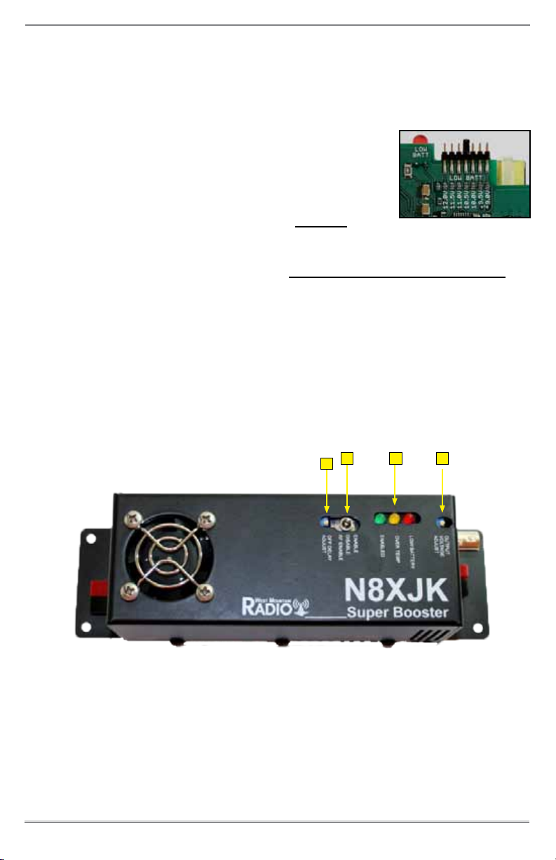
The Booster allows a user to maintain any output voltage greater than battery
voltage, up to 15 volts. The Boost function can be enabled manually via a front
panel switch, via the RF detect input attached to the antenna lead of the transmitter
or using the optional remote. This allows the Booster to supply boosted voltage
only when transmitting.
In bypass (disable mode), the battery voltage is passed to the attached radio with
no regulation. In this mode, the lter stage of the supply is still in-circuit and will
act to lter the battery voltage to the radio. This can help to reduce noise induced
into the power circuit from other attached electronic devices such as chargers,
Alternators, Ignition systems.
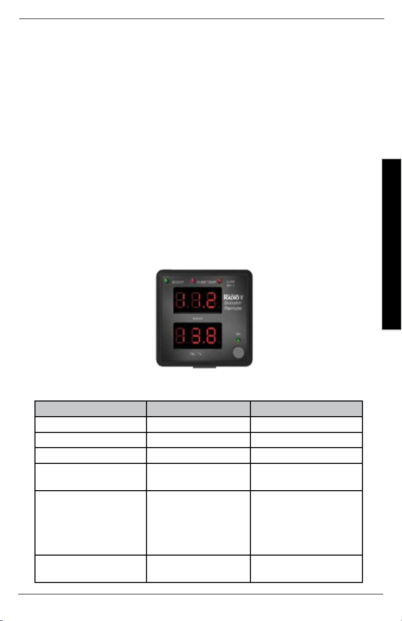
West Mountain Radio also sells separately a Remote Monitor/Control unit.
INTRODUCTION

2
West Mountain Radio Operating Manual
OPERATION IN CRITICAL SITUATIONS
The Super Booster was designed to aid communications from less than optimal
power sources and it is not intended for critical life support applications. West
Mountain Radio and its agents cannot be held responsible for failure of the Boost
Regulator in life or death situations or in situations where property loss or damage
may occur. It is the responsibility of the operator of the boost regulator to ensure
that the failure of the boost regulator will not result in loss of life or property damage.
FEATURES
The Super Booster allows the following:
• Maintain any output voltage greater than battery voltage up to 15 volts.
• Enable boost manually or with the RF detect input only when transmitting.
• Battery voltage is present at the output with the supply turned o!
• Boost voltages up to 40 Amps Input.
• Boosters can be connected in parallel to increase the current (80A, 120A...).
• Protect the battery with the low battery voltage shuto feature.
INSTALLATION & SET-UP
1. Install the Super Booster between the power source and the radio. If using
a RIGrunner, connect the output side of the Booster to the DCIN of the
RIGrunner and the input side of the Booster to the DC power source. If
using a PWRgate, connect the input side of the Booster to the output of the
PWRgate. It is recommended to place the Booster into bypass mode when
the PWRgate is running from the PSU. Enable the Booster when running
from the PWRgate battery during such times as a power blackout.
DO NOT install between the battery and PWRgate.
DO NOT use the Booster to charge batteries.
AVOID using a switch mode power supply to supply power to the Booster.
Improperly or poorly designed switch mode power supplies may not function
correctly with the boost regulator attached as a load.
AVOID using a ground return that is part of a vehicle chassis ground. The
input leads should be attached directly to the battery or power source.
NOTE:
The unit comes tted with Powerpole®connectors for easy installation to the
power system. Input (power source) connects on the left side of the case.
Output (load) connects on the right side of the case. Make sure to only
connect the RED lead to POSITIVE, and the BLACK lead to NEGATIVE.
Visit the West Mountain Radio web site for a large variety of cables with
Powerpole®connectors.
Anderson Power Products® and Powerpole® is a registered Anderson Power Products, Inc.

3
West Mountain Radio Operating Manual
INSTALLATION & SET-UP
2. Install the unit in a cool, dry, ventilated location. For example the engine
compartment would be a bad location due to heat. When operating at 40A
continuous the unit should be in an area with an ambient temperature of
under 110ºF. Note that when used continuously at the higher currents the
bottom center of the enclosure can get hot enough to burn skin. For this
reason we recommend the enclosure be fastened down using the mounting
holes on the anges. It is acceptable to mount to wood since the heat will
not be so great as to burn the wood. Some plastics will melt. Metals are
a good pick but remember that the opposite side of the metal may still be
hot enough to burn skin. Do not block the ventilation holes on the booster.
The booster will shut down if it gets too hot.
3. Using the RF sensor: Connect an RF-connector in-line with the antenna
feed and run a short thin coax (any gauge) to the BNC connector on the
Booster. Contact West Mountain Radio if the transmitter is over 200W for
help coupling the RF to the Booster.
4. Boosters in parallel: See Figure
1 for the correct conguration.
A. Both the inputs and outputs
should be connected in
parallel. The cables to
each booster should be
tied using a high current
connection. For example
a good pick is to use ring
terminals to a terminal
block or simple bolts.
Make sure all connectors
used on the single wire are
rated for the high current
you will be using.
B. The master of the rst
booster needs to be
connected to the slave
connector of the second
unit using common phone
cables. Repeat for each additional booster.
DO NOT install the unit in an area with ammable gases or liquids
WARNING: Please read the above paragraph
Figure 1

4
West Mountain Radio Operating Manual
5. Using the Remote: Connect it using CAT-3 or better Ethernet cable. The
remote comes with a 6-feet cable. Longer cables may also be used. The
remote has a magnet that may be stuck to the back of the plastic enclosure
to allow mounting directly to a metal surface.
6. The booster has an internal jumper to select the
minimum battery voltage. From the factory it is set
to 10.5V. This is the minimum voltage manufactures
specify for lead acid batteries. See Figure 2. If this
needs to be changed, remove the enclosure screws,
remove the fuse from input end and carefully lift up
the end on the input side and slide over the BNC connector to open the
case. Disconnect the fan wires attached to the top and bottom. Watch a
short video for specic instructions: www.westmountainradio.com/bbda
7. Fuse: The ATC type fuse on the input side of the booster is used to protect
the battery from excessive current. The booster includes a 40A fuse. The
fuse may be changed to a lower value if desired for protection of other
system components downstream. Be aware the output current will be less
while boosting. For example if the battery is 11V and the boost is set to
13.8V, then a 40A input is around 29A output.
OPERATION
1. O Delay Adjust: This RF o delay trim pot adjusts how long the booster
remains on after the transmission stops.
2. Mode switch:
DISABLE will shut the unit o and the battery voltage is passed through to
the output as-is.
ENABLE will turn the booster to be continuously on.
Figure 2
1234

5
West Mountain Radio Operating Manual
INSTALLATION & SET-UP
RF ENABLE will turn the booster on only when RF is detected. If the remote
is being used set the switch to DISABLE and use the remote to turn the unit
on. If this switch is set to ENABLE or RF ENABLE the remote will not be able
to turn the unit o.
3. LEDs:
Green - Booster is boosting
Yellow - Unit is too hot and Booster was disabled
Red - Battery voltage is too low, Booster is disabled
4. Output Voltage Adjust: Trim pot that is factory adjusted for 13.8V. Most
radios can tolerate up to 15V and transmit more eciently with higher
voltages. Most radios should not be used for transmit below 11.7V. Connect
a volt meter to the output of the Booster when adjusting. If using very long
cable to the radio , take account for voltage drop, then put the meter near
the radio and adjust to the maximum voltage the radio can tolerate while in
receive mode.
BOOSTER REMOTE OPERATION
The remote has a single push button that may be used as follows:
State Action Result
Unit OFF Single button press Unit turns ON
Unit ON, not boosting Single button press Boosting begins
Unit ON, boosting Single button press Boosting stops
Unit ON Hold button down for
2 seconds
Unit shuts OFF
Unit ON Three quick button
presses
Display shows mini-
mum battery voltage
and maximum output
voltage for several
seconds
Display shows min/
max
Hold down button for
2 seconds
Min/Max is reset

6
West Mountain Radio Operating Manual
SPECIFICATIONS
Limits:
Minimum input voltage: 9VDC
Maximum input voltage: 15VDC
Minimum output voltage: 9VDC
Maximum output voltage: 15VDC
Maximum current: 40A Input (per unit)
RF Voltage maximum 100Vp-p (200W)
Current Consumption:
Power O 1.5mA
Standby 24.4mA
Enabled Booster 40mA
Low Battery/Overtemp 39mA
RF Enable:
RF detect threshold 3.3Vp-p typical. (0.22W)
RF “Turn On” delay 2ms typical
RF “Turn O” delay range 2-500ms typical
Low Battery Lockout:
Jumper Selectable 9V, 9.5V, 10V, 10.5V, 11V, 11.5V, 12V
Voltage drop when booster o: 0.76V at 20A load
Eciency: Around 90%
Temperature:
Maximum ambient temperature (before shutdown):
32A continuous Output 110ºF
Maximum case temperature (before shutdown):
Sides 115ºF
Bottom center 139ºF
Internal 162ºF
Output Ripple:
Load = 20A (100W xmit) 4.2mV RMS, 12mVp-p
Load = 3A (receive) 3.5mV RMS, 10mVp-p
Connectors: Anderson Powerpole®, 45A
Size: 8.0” x 2.3” x 2.2”
Weight: 0. lbs
Mounting Holes: Four - 0.175 d, #8 hardware

7
West Mountain Radio Operating Manual
ACCESSORIES
Order Sku#
Powerpole® Extension Cable, 3 ft. #58531-1082
12AWG 30A Powerpole® to Powerpole® connectors
Powerpole® Extension Cable, 6 ft. #58531-1083
12AWG 30A Powerpole® to Powerpole® connectors
Powerpole® Extension Cable, 10 ft. #58531-1084
12AWG 30A Powerpole® to Powerpole® connectors
Powerpole® to Batt Ring Term Cable, 6ft. #58257-1068
with 30A Fuse
Powerpole® to Batt Ring Term Cable, 6ft. #58257-1533
with 50A Fuse
Powerpole® to 1/4” Ring Term Cable, 3ft. #58531-1079
Powerpole® to 1/4” Ring Term Cable, 6ft. #58531-1080
Powerpole® to 1/4” Ring Term Cable, 10ft. #58531-1081
15A. Powerpole® Connector-12 Pair #58257-1093
30A. Powerpole® Connector-12 Pair #58257-1095
45A. Powerpole® Connector-12 Pair #58257-1099
PWRcrimp Crimp Tool #58568-1049
Mounting Magnet #58515-1785
To purchase or view other accessories available,
call or go online at:
www.westmountainradio.com/shop

N8XJK Super Booster & Booster Remote Warranty
N8XJK Super Booster & Booster Remote is warranted against failure due to defects in
workmanship or materials for one year after the date of purchase from West Mountain
Radio. Warranty does not cover damage caused by abuse, accident, misuse, improper or
abnormal usage, failure to follow instructions, improper installation, alteration, lightning, or
other incidence of excessive voltage or current. If failure occurs within this period, return
the N8XJK Super Booster & Booster Remote or accessory to West Mountain Radio at
your shipping expense. The device or accessory will be repaired or replaced, at our option,
without charge, and returned to you at our shipping expense. Repaired or replaced items are
warranted for the remainder of the original warranty period. You will be charged for repair or
replacement of the N8XJK Super Booster & Booster Remote or accessory made after the
expiration of the warranty period.
West Mountain Radio shall have no liability or responsibility to customer or any other person
or entity with respect to any liability, loss, or damage caused directly or indirectly by use or
performance of the products or arising out of any breach of this warranty, including, but not
limited to, any damages resulting from inconvenience, loss of time, data, property, revenue,
or profit, or any indirect, special incidental, or consequential damages, even if West Mountain
Radio has been advised of such damages.
Except as provided herein, West Mountain Radio makes no express warranties and any
implied warranties, including fitness for a particular purpose, are limited in duration to the
stated duration provided herein.
www.westmountainradio.com
1020 Spring City Drive, Waukesha, WI 53186
tel 262-522-6503 fax 262-522-6504
Table of contents