Westcraft 7775697 Owner's manual

7775697
Westcraft 52" Five-Blade Ceiling Fan,
Brushed Nickel
WESTCRAFT.COM
Manufactured for/ Fabricado para: PL Sourcing, Inc.
P.O. Box 2778 Newport News, VA 23602
©2018 Ferguson Enterprises, Inc. 911181
CEILING FAN INSTALLATION AND
OPERATION INSTRUCTION
READ AND SAVE THeSE INSTRUCTIONS

WESTCRAFT.COM
Manufactured for/ Fabricado para: PL Sourcing, Inc.
P.O. Box 2778 Newport News, VA 23602
©2018 Ferguson Enterprises, Inc. 911181
WARNING:
circuit panel before youbegin the fan installationorbefore servicing the fan or installing accessories.
1. Read all instructionssafetyinformation care fullybefore installing your fan and save these instructions.
CAUTION: To avoid personal injury,the use of gloves maybe necessary while handing fan parts with sharp
edges.
2. Make sure all ele ctrical connections comply with Local Codes or Ordinances, the National Electrical Code,
and ANSI/NFPA 70-1999. If you are unfamiliar with electrical wiring or if the house /building wires are different
colors thanthose referred to in the instructions,please use a qualified electrician.
3. Make sure you have a locationselected for your fan that allows clear space forthe blades to rotate,and at
least senen(7) feet (2.13meters) of clearance between the floorand the fanblade tips. The fan should be
mounted so that the tips of the blades are at least thirty (30) inches (76 centimeters) from walls or other upright
structures.
4. The outlet box and ceiling support joist used must be securely mounted and capable of supporting at least
35 pounds (16 kilograms). The oulet box must be supported directly by the building structure Use only ETL or
UL listed outlet boxes marked “FOR FAN SUPPORT.”
WARNING: To reduce the riskof fire,electrical shock,orpersonal injury,mount to the outlet box marked
"Acceptable for FanSupport," and use the mounting screws provided with the outlet box.Most outlet boxes
commonly used forthe support of lighting fixturesare not acceptable for fan support and may need to be
replaced. Consult a qualified electricianif indoubt.
WARNING: To reduce the risk of fire,electrical shock,orpersonal injury,wire connectors provided with this fan
are designed to accept onlyone12 gauge house wire and two lead wires from the fan. If your house wire islarger
than 12 gauge or there is more than one house wire to connect to the two fanlead wires, consult an electrician
for the proper size wire connectors to use.
5. Electrical diagrams are for reference only. Light kits that are not packed with the fan must be ETL or ULlisted
and marked suitable foruse with the model fan you are installing. Switches must be ETL orULeneral use
switches. Refer to the instructions packaged with the light kitsand switches for proper assembly.
6. After installationiscomplete,check that all connections are absolutely secure.
7. After making electrical connections,spliced conductors should be turned upward and pushed carefully up
into the outlet box. The wires should be spread apart withthe grounded conductor and the
equipment-grounding conductor on opposite sides of the outlet box.
WARNING: To reduce the risk of electrical shock,fire and to prevent humming noise do not use this fan withany
solid state speed control device or control fan speed with a full range dimmer switch.[Using a full range dimmer
switchto control fan speed will cause a loud humming noise from fan.] (Note:This fan issuitable for usewith
remote control.)
8. Do not operate the reverse switch until fan hascome to a complete stop.
9. Do not insert anything betweenthe fanblades while they are rotating.
WARNING: To reduce the risk of personal injury,do not bend the blade arms during assembly or after
installation. Do not insert objects into the pathof the blades.
WARNING: To avoid personal injury or damage to the fan and other items,be cautious when working around or
cleaning the fan.
10. Do not use water or detergents when cleaning the fanorfan blades. A dry dust cloth or lightly dampened
cloth will be suitable for most cleaning.
WARNING: To reduce the risk of personal injury, use onlyparts provided withthis fan. The use of parts OTHER
than those provided with thisfan will void the warranty.
NOTE: The important safetyprecautions and instructions appearing in the manual are not meant to cover all
possible conditions and situations that may occur.It must be understood that common sense and cautionare
necessary factors in the installation and operationof this fan.
To reduce the riskof electrical shock,turn off the electricity to the fan at the main fuse box or
.
SAFETY INFORMATION

WESTCRAFT.COM
Manufactured for/ Fabricado para: PL Sourcing, Inc.
P.O. Box 2778 Newport News, VA 23602
©2018 Ferguson Enterprises, Inc. 911181
No Description
A Mounting Bracket (1)
B Canopy (1)
C Downrod Assemble(1)
D
E
Motor Assemble (1)
F
Light kit (1)
G
H
Glass Shade(1)
I
Blade (5)
K
Parts Pack
(1)
Balance Pack (1)
J
Blade Arm (5)
LED Bulb (E26*6.5W)
(1)
LM
A
B
C
D
F
E
G
H
I
J
K
PREPARATION
Before beginning assembly assembly,installation or operation of product,make sure all parts are present.
Compare parts with package contents list and diagram above. If any part is missing or damaged,do not
attempt to assemble,install or operate the product. Contact customer service for replacement parts.
. Estimated Assembly Time: 45 minutes.
. Tools Required for Assembly: (not included).
Electrical Tape Phillips Screwdriver A/C Tester Light Stepladder
Pliers Safety Glasses Tape Measure Wire Cutters Wire Strippers
PACKAGE CONTENTS

WESTCRAFT.COM
Manufactured for/ Fabricado para: PL Sourcing, Inc.
P.O. Box 2778 Newport News, VA 23602
©2018 Ferguson Enterprises, Inc. 911181
INSTALLING YOUR FAN
WARNING: When using an existing outlet box,make sure the box is securely attached to the building structure and can
support the full weight of the fan. Failure to do this can result in serious injury or death.
If using the angle mount, check to make sure the ceiling angle is not steeper than 25°.
1.
Turn off circuit
breakers and wall
switch to the
fan supplyline l
eads.
Fig.1 2.
Detemine mounting
method:
A-Closemount
B-Downrod mount
or angle mount
Fig.2 Fig.3
3.
Check to make sure
blades are at least 30
inches from any
obstruction. Check
downrod length to
ensure blades are at
least 7 feet above the floor.
Important: If using the angle mount, make sure open end of mounting bracket is installed faceing the roof.
1.
Secure mounting
bracket to electrical
box using screws,
spring washers, and
flat washers (size 8
or M5) provided with
the electrical box.
2.
If using closemount
installation, remove
rubber washer from
bottom of the canopy.
Fig.1 Fig.2
Follow mounting instructions A or B below for mounting method chosen.
CLOSEMOUNT STYLE FAN MOUNTING
Helpful Hint: Close style mounting is more suitable for ceilings lower than 8 feet (2.43m) high. The downrod, hanging ball, rubber
washer, and the canopy are not used inthis type of installation.
1.
If necessary, remove
every other screw
and lock washer
from top of motor
housing. (These
screws may already
be in a hardware
pack .)
Fig.1 Fig.2 Fig.3
2.
Pull wires through the
canopy hole and attach
canopy to motor housing
using the 3 screws with 3
lock washers provided.
3.
Temporarily hang fan onto
the tab on the mounting
bracket until wiring is
complete. Use one of
the non-slotted holes in
the canopy.
Helpful Hint: Downrod style mounting is best suited for ceilings 8 feet (2.43m) high or higher. For taller ceilings you may want to
use a longer downrod (not included).Angle style mounting is best suited for angled or vaulted ceilings. A longer downrod will
be needed to ensure proper blade clearance.
DOWNROD OR ANGLE STYLE FAN MOUNTING
1.
Insert downrod
through canopy.
Thread wires
from motor
housing through
downrod and
flange cover.
2.
Remove clip and pin from
housing yoke. Slip
downrod into housing
yoke, aligning holes in
housing yoke with holes
in downrod. Reinstall pin
and clip. Tightendownrod
set screws and then tighten nuts.
3.
Install ball end of
downrod into hanging
bracket opening. Align
slot in ball with tab in
bracket.
Fig.1 Fig.2 Fig.3
WARNING: Failure to align slot in ball with tab may result in serious injury or death.

WESTCRAFT.COM
Manufactured for/ Fabricado para: PL Sourcing, Inc.
P.O. Box 2778 Newport News, VA 23602
©2018 Ferguson Enterprises, Inc. 911181
Tighten blades to
blade brackets by
using blade screws
and washers.
Blade Screw
Washer
Blade Arm
Fig.1
Fig.2Fig.3
Fig.4
NOTE: Before installing blade
brackets to the motor, please
remove the plastic inserts.
Remove the motor screws and
washersfrom the motor
assembly.
Secure blade brackets to the motor
with washers and motor screws.
Motor Screw
Blade Arm
Blade
3. Light Kit Assembly
2. Blade Assembly
1. Canopy Assembly
Remove 3 screws from light kit fitter. Locate
BLACK (or BLUE ) and WHITE wires in the
switch housing labeled LIGHT. Remove and
discard plastic that holds these 2 wires
together.
Next, locate WHITE and BLACK wires in light
kit fitter labeled LIGHT.
ConnectWHITE wire from switch housing to
WHITE wire from light kit fitter. Connect BLACK
(or BLUE) wire from switch housing to BLACK
wire from light kit fitter. Be sure molex
connections snap together completely.
Align holesinlight kit fitter with holes in switch
housing. Attach light kit fitter withscrews that
were removed . Securely tighten all 3 screws with
Phillips screwdriver.
Install 1X6.5wLED bulb
Mount the glassshadeson the light fixture by
unscrewing partway the thumb xcrews on the
glass holders, inserting the glass, then gently
tightening the thumb screwsby hand evenly to
the glass. DO NOT OVER TIGHTEN. (Fig.4)
Important: When replacing bulbs, please allow
bulb(s) and glass shade(s) to cool downbefore
touching them.
Fig.1
WIRING
1.
If using downrod
or angle style
mounting,connect
green wire
from downrod to
green wire on
mounting bracket.
2.
Strip 3/4 in.of
insulation from wire
ends. Twist stripped
ends together with
pliers.Snip ends.
Fig.2 Fig.3
3.
Screw wire nuts on in
a clockwise direction
Tape nuts and weires
together.
WARNING: Be sure no bare wire orwire strands are visible after making connection. place green and white connections
on opposite side of fromthe black and blue (if applicable) connections.
Temporarily lift canopyto mounting bracket
to determine which screws align with slotted
holes in canopy and partially loosen these
screws.Remove the othertwo screws.
Raise canopyto mounting bracket, aligning
slotted holes in canopy with loosened screws
in mounting bracket. Twist canopyto lock.
Insert the other two screws in nonslotted
holes. Tighten all screws securely.
FINAL INSTALLATION
NOTE: Before starting installation, disconnect the
power by turnning off the circuit breaker or
removing the fuse at fuse box.Turning power
off using the fan switch is not sufficient to prevent
electric shock.
Restore power and your light kit is ready for
operation.
motor housing
Thumb
screws switch
housing
fan
pull chain
extension
white
wire
black
(or blue)
wire
white wire black wire
molex connections
thumb
screws light kit fitter
light
pull chain
extension

WESTCRAFT.COM
Manufactured for/ Fabricado para: PL Sourcing, Inc.
P.O. Box 2778 Newport News, VA 23602
©2018 Ferguson Enterprises, Inc. 911181
CARE AND MAINTENANCE
. Every month inspect the ceiling fan for dust. Use a dry mop to clean.
. If the ceiling fan is not used for a long time, turn on the ceiling fan and let it tun several minutes in order to prevent rusting.
. If the ceiling fan has been running over 36 hours, let the ceiling fan stop at least one hour for cooling.
. Twice yearly, check for loose screws and tighten if necessary.
TROUBLESHOOTING GUIDE
Minor problems can often be fixed without an electrician. Before beginning any work,shut off the
power supply to avoid electrical shock.
Problem Cause Solution
Fan does not move.
Chain switch is “off”. Pull chain switch
Reversing switch not engaged. Push switch firmly either way.
Power is off or fuse is blown. Turn power on or check fuse.
Bad wire connection. Turn power off. Loosen canopy,check all connections.
Noisy operation.
Blades are loose. Tighten all blade screws.
Cracked blade. Replace blades.
Bab wire connection. Check all wire connections.
Excessive wobbling.
Unbalanced blades. Switch with blade from opposite side.
Blades are loose. Tighten all blade screws
Blade brackets incorrectly attached. Reinstall blade brackets.
Fan not securely mounted. Turn off power.Carefully loosen canopy.remount securely.
Fan too close to vaulted ceiling. Lower or move fan.
1
The fan speed pull
chain has four
posotions. One pull is
hight, two is medium,
three is for low and
four is to turn off.
Fig.1
2
pull the light pull
chain (if applicable)
to turn the light on
or off.
3
Use the fan reversing
switch to optimize your
fan for seasonal
performance.
Note: Wait for fan to
stop before reversing
the switch.
Fig.2 Fig.3
IMPORTANT: Turn fan off at wall switch and let blades come to a complete stop before manually activating the reverse switch.
Use the fan reversing switch to optimize your fan for seasonal performance.
Note: Wait for fan to stop before moving the switch.The reverse switch is located on the switch housing.
Fig.1
1
In warmer weather,
counterclock-wise
movement of the fan will
result in downward airflow
creating a wind chill effect.
2.
In cooler weather, clockwise
movement of the fan will
result in upward airflow that
can help move stagnant, hot
air off the ceiling area. Fig.2

WESTCRAFT.COM
Manufactured for/ Fabricado para: PL Sourcing, Inc.
P.O. Box 2778 Newport News, VA 23602
©2018 Ferguson Enterprises, Inc. 911181
DYNAMIC BLADE BALANCING KIT
PREFACE
Your ceiling fan may sometimes have wobbling problems when operating due to irregularity in the blades or the blade
brackets. Improper assembly in the mounting systemmay cause some additional problems. This balancing kit canbe
used to fix wobbling problem.
BALANCING WEIGHT
MEASURING
POINT
YARDSTICK
PLASTIC CLIP
CENTERLINE
COUNTER-
CLOCKWISE
1
2
3
4
5
6
7
8
9
DYNAMIC BLADE BALANCING KIT FOR CEILING FANS
1. Make sure that all blades are firmly screwed into the blade brackets.
2. Make sure that all blade brackets are firmly secured to the motor housing.
3. By looking up at the fanfrom below, check and be certainthat none of the blade brackets are bent and that none
of the blades are out of position.
4. Use a yardstick to checkthe blade tracking. Put the yardstick up against the ceiling vertically and against the
outside leading edge of a blade. Note the distance of the edge of blade to the ceiling. Carefully turn the blades
slowly by hand to check the remaining blades. All distances should be the same.
Operate the fan ten minutes. After following all the steps and if the wobbling problem is not solved, a dynamic
balancing needsto be done by balancing kit. Follow the procedure listed below:
●Turn the fanoff. Select one blade and place the plastic clip onit, where the plastic clip locates is halfway between
the blade bracket and the blade tip on the edge of the blade.Caution: The plastic clip should be placed on the
windward edge of the blade for fearof clip’s flying off.
●Turn the fan on (set the speed that causes the wobble most). Observe if the wobble is betteror worse. Turn the fan
off and move the clip to the next blade. Do the same for all blades and note on whichblade the clip reduces the
wobble most. Place the clip on the blade which showed the most improvement. Move the clip inward and outward
on this blade and operate the fan to find the position where the clip gives the most improvement. Caution: Stay
clearof the blades. If the clip, forany reason,isnot secure, injurycould result .
●Once the exact position is determined,place a weight onthe top of the blade, on itscenterline and most close to the
clip.Peel the paper off of the back of the weight and pressfirmly to ensure that it is securely attached to the blade.
Remove the clip. Caution: Cleanthe surface of fan blade before placing the balancing weight so that the balancing
weight can be firmly attached on it.
WARRANTY
Limited Warranty Terms
If any part of your ceiling fan motor fails within one year of the date of purchase due to a defect in material or workmanship,
as determined by Ferguson, Ferguson will provide a replacement product or part free of charge. If there is no replacement
product or part to be provided a comparable product or part will be provided.
Labor is excluded from coverage. Warranty does not cover labor nor any costs or fees associated with the labor required
to install, remove, or raplce a fan or any fan parts (includes electrician's fees).

7775697
WESTCRAFT Abano de Cinco Hojas de Montaje Hugger,
52”, NÍQUEL CEPILLADO
WESTCRAFT.COM
Fabricado por: PL Sourcing, Inc.
Botón de correo: 2778 Newport News, VA 23602
© 2018 Ferguson Enterprises, Inc. 911181
INSTRUCCI N DE INSTALACIÓN Y OPERACIÓN DE ABANO
LEA Y GUARDE ESTAS INSTRUCCIONES

WESTCRAFT.COM
Fabricado por: PL Sourcing, Inc.
Botón de correo: 2778 Newport News, VA 23602
© 2018 Ferguson Enterprises, Inc. 911181
ADVERTENCIA: Para reducir el riesgo de descarga eléctrica, apague la electricidad del abano en la caja principal
de fusible o panel de circuito antes de empezar la instalación del abano o antes de reparar el abano o instalar
accesorios.
1. Lea la información de seguridad con cuidado antes instalar nuestro abano y guarde estas instrucciones.
PRECAUCIONES: para evitar la lesión personal, es necesario usar los guantes mientras manipula partes del
abano con bordes afilados.
2. Asegúrese de que todas las conexiones electrónicas cumplan con Códigos u Ordenanzas Locales, el
Código Eléctrico Nacional y ANSI/NFPA 70-1999. Si no está familiarizado con el cableado eléctrico o
si los cables de casa/edificio son de diferentes colores a los mencionados en las instrucciones, consulte
a un electricista calificado.
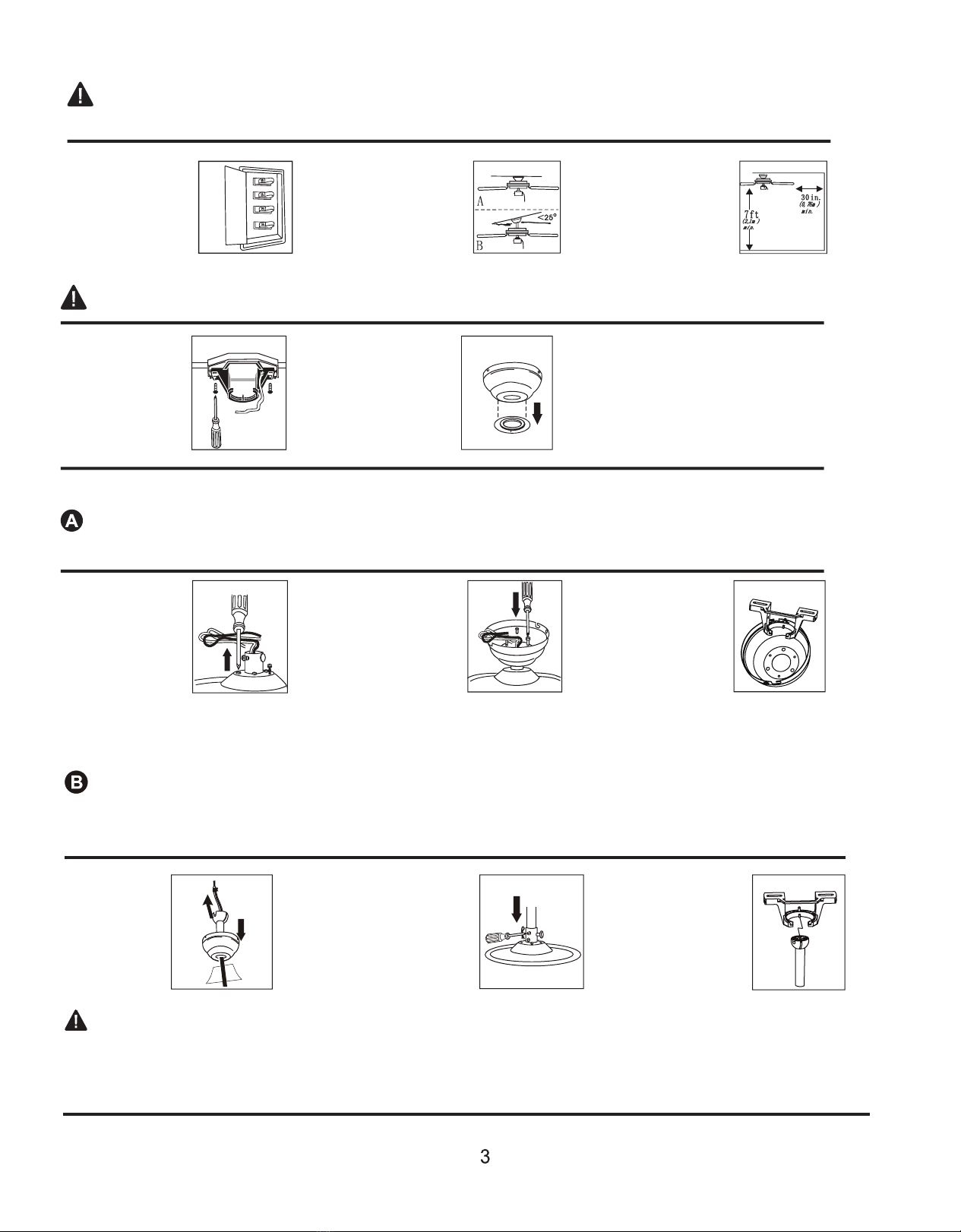
3. Asegúrese de que tenga una locación seleccionada para su abano que permite un espacio libre para que
gire las hojas, y al menos hay una distancia de (7) pies (2.13 metros) entre el piso y las puntas de las hojas
del abano. El abano debe montarse de manera que las puntas de las hojas estén al menos a treinta (30)
pulgadas (76 centímetros) de las paredes o otras estructuras verticales.
4. La caja de salida y la viga de soporte del techo deben estar montadas seguramente y ser capaces de soportar
al menos 35 libras (16 kilómetros). La caja de salida debe ser soportado directamente por la estructura del
edificio. Use solo cajas de salida listadas por ETL o UL marcadas como “PARA SOPORTE DEL ABANO”.
ADVERTENCIA: Para reducir el riesgo de fuego, descarga eléctrica, o lesión personal, montado en la caja de salida
marcada “Aceptable para Soporte de “Abano”, y use los tornillos de montaje provistos con la caja de salida. La
mayoría de las cajas de salida comúnmente utilizadas para el soporte de los accesorios de iluminación no son
aceptables para el soporte del abano y pueden causar el reemplazo. Consulte a un electricista calificado en caso
de duda.
ADVERTENCIA: Para reducir el riesgo de fuego, descarga eléctrica, o lesión personal, los conectores de cable provistos
con este abano son diseñados para aceptar solo cable de casa de calibre 12 y dos cables conductores del abano. Si el
cable de su casa es más grande que calibre 12 o hay más de un cable de casa para conectar a los dos cables conductores
de abano, consulte a un electricista para usar los conectores de tamaño del cable adecuado.
5. Los diagramas eléctricos son solo para referencia. Los kits que no se incluyen en el abano deben estar listados en
ETL o UL and marcados como adecuados para usar con el modelo del abano que está instalando. Los interruptores
deben ser interruptores de uso ETL o UL. Consulte a las instrucciones incluidas con los kits de luz y los interruptores
para un montaje correcto.
6. Después de terminar la instalación, compruebe que todas las conexiones son absolutamente seguras.
7. Después de hacer las conexiones eléctricas, los conductores empalmados deben girarse hacia arriba y empujarse con
cuidado hacia arriba en la caja de salida. Los cables deben ser separado con el conductor a tierra y el conductor de
conexión a tierra del equipo en lados opuestos de la caja de salida.
ADVERTENCIA: Para reducir el riesgo de descarga eléctrica, fuego y para evitar el zumbido, no use este abano con
cualquier dispositivo de control de velocidad de estado sólido o velocidad del abano de control con un interruptor
de regulación de rango completo. (Usando un interruptor de regulación de rango completo para controlar la
velocidad del abano puede causar un zumbido fuerte desde el abano) (Nota: Este abano no es adecuado para el
uso con control remoto).
8. No opere el interruptor de reversa hasta que el abano detenga completamente.
9. No inserte nada entre las hojas del abano mientras está girando.
ADVERTENCIA: Para reducir el riesgo de lesión personal, no doble los brazos de la hoja durante el montaje o después
de la instalación. No inserte objetos en la ruta de las hojas.
ADVERTENCIA: Para evitar lesiones personales o daños al abano y otros artículos, tenga cuidado al trabajar cerca o
limpiar el abano.
10. No use agua o detergente cuando limpie el abano o hojas de abano. Es adecuado usar un paño seco o un paño
ligeramente humedecido para limpiarlo.
ADVERTENCIA: Para evitar lesiones personales, use solo partes provistos con este abano. El uso de las OTRAS partes
que las provistas con este abano anularán la Garantía.
NOTA: Las precauciones y instrucciones de seguridad importantes aparecidas en este manual no significan cubrir todas
las condicionesy situaciones posibles que pueden producir. Debe entenderse que el sentido común y la precaución son
factores necesarios en la instalación y la operación de este abano.
INFORMACIÓN DE SEGURIDAD

WESTCRAFT.COM
Fabricado por: PL Sourcing, Inc.
Botón de correo: 2778 Newport News, VA 23602
© 2018 Ferguson Enterprises, Inc. 911181
No DESCRIPCIÓN
A Soporte de Montaje (1)
B Cubierta (1)
CMontaje de Downrod (Varilla Colgante)(1)
D
E
Montaje del motor (1)
F
Kit de luz (1)
G
H
Carcasa de vidrio
(1)
I
Hojas (5)
K
Paquete de partas(1)
Paquete de Equilibrio (1)
J
Brazo de la Hoja (5)
Bombilla LED (E26 * 6.5W) (1)
LM
A
B
C
D
F
E
G
H
I
J
K
PREPARACIÓN
PREPARACIÓN
Antes de empezar el montaje, la instalación o la operación del producto, asegúrese de que todas las partes
sean completas. Compare las partes con la lista de paquete y diagrama de arriba. Si se pierde o daña
cualquier parte, no intente montar, instalar o operar el producto. Póngase en contacto con servicio al cliente
para las partes de reemplazo.
. Tiempo de montaje estimado: 45 minutos.
. Herramientas requeridas para montarse: (no incluida)
Cinta Eléctrica Destornillador Phillips Probador de A/C Escalera ligera
Alicates Lentes de Seguridad Cinta Métrica Cortadores de alambre Pelacables

WESTCRAFT.COM
Manufactured for/ Fabricado para: PL Sourcing, Inc.
P.O. Box 2778 Newport News, VA 23602
©2018 Ferguson Enterprises, Inc. 911181
INSTALAR SU ABANO
WARNING: Al usar una caja de toma existente,asegúrese de que la caja esté bienadecuada para la estructura
del edificio y pueda soportar todo el peso del abano. De lo contrario, resultará grave lesión o muerte.
Al usarel montaje de ángulo, compruebe para asegurarse de que el ángulo del techo no excede a 25°.
1.
Apague los
disyuntores e
interruptoresa los
cabezales de
cables de
alimentación
del abano.
Fig.1 2.
Determine el método
de montaje:
A. Montaje cerrado
B. Montaje Downrod
o montaje de ángulo
Fig.2 Fig.3
3.
Compruebe para
asegurarse de que las
hojas sean al menos
30 pulgadas desde
cualquier obstrucción.
Compruebe la longitud
de downrod para asegurarse
las hojas seanal menos 7 pies
sobre el piso.
Importante: Al usarel montaje de ángulo, asegúrese de que el extremo abierto del soporte de montaje sea
instalado de cara al techo.
1.
Fije soporte de
montaje a la caja
eléctrica usando
tornillos, arandelas
de resorte y
arandelas planas
(tamaño 8 o M5)
provistosconla caja eléctrica.
2.
Al usarinstalación de
montaje cerrado, retire
la arandela de goma de
la parte inferior de la
cubierta.
Fig.1 Fig.2
Siga las instrucciones de montaje A o B para elegir el método de montaje.
MONTAJE DE ABANO DE ESTILO CERRADO
Consejo útil: el montaje de estilo cerrado es más adecuado para techos interior a8 pies (2.43m). Lavarilla colgante, la bola colgante,
la arandela de goma, y la cubierta no se utilizan en este método de instalación.
1.
Si es necesario,
retire todos losotros
tornillos y arandela
de seguridad de la
parte superior de la
carcasa del motor.
(Estos tornillos
pueden ser enel
paquete de hardware.)
Fig.1 Fig.2 Fig.3
2.
Pasen los cables a través
de la cubierta yfije la
cubierta a la carcasa
del motor usando los 3
tornillos con3 arandelas
de seguridad provistas.
3.
Temporalmente cuelgue
el abano en la pestaña
del soporte de montaje
hasta que el cableado
se complete. Use uno
de los agujeros sin
ranuras en la cubierta.
Consejo útil: el montaje de estilo convarilla colgante es mejor adecuado para techos de altura de 8 pies omás altos. Para techos
más altos, puede desear usar una varilla colgante más largo (no incluido). Elmontaje de estilo de ángulo es mejor adecuado para
techos en ángulo o abovedados. Una varilla colgante más larga será necesaria para asegurar el espacio de hoja adecuado.
MONTAJE DE ABANO DE ESTILO CON VARILLA COLGANTE O ÁNGULO
1.
Inserte la varilla
colgante a través
de la cubierta.
Enrosque los
cables de la
carcasa del
motor a través
de la varilla
colgante y la
cubierta de la brida.
2.
Retire clip ypin del yoga de la
carcasa. Deslice la varilla
colgante en el yoga de carcasa,
alineando losorificios en yoga
de carcasa conagujeros en
varilla colgante. Reinstale pin y
clip. Apriete los tornillos de
montaje de la varilla colgante
y luego apriete tuercas.
3.
Instale el extremo de
la bola de varilla
colgante en la abertura
de soporte colgante.
Alinee ranura en bola
conla pestaña en el
soporte.
Fig.1 Fig.2 Fig.3
ADVERTENCIA: El fracaso de alinearla ranura en bola conpestaña puede resultar en graves lesiones o muertes.

WESTCRAFT.COM
Fabricado por: PL Sourcing, Inc.
Botón de correo: 2778 Newport News, VA 23602
© 2018 Ferguson Enterprises, Inc. 911181
Apriete las hojas a
los soportes de
hoja utilizando
tornillos y arandelas
de hojas.
Tornillo de hoja
Arandela
Brazo de Hoja
Fig.1
Fig.2 Fig.3
Fig.4
NOTA: Antes de instalar los
soportes de la hoja en el motor,
retire los insertos de plástico
.
Retire los tornillos y arandelas
del motor del conjunto del
motor.
Fije los soportes de la
hoja al motor con arandelas y
tornillos del motor.
Tornillo de
motor
Brazo de Hoja
Brazo
3. Montaje de Kit de Luz
2. Montaje de las hojas
1. Montaje de la cubierta
Retire los 3 tornillos del kit de luz. Ubique los cables
NEGRO (o AZUL) y BLANCO en la caja del interruptor
con la etiqueta LUZ. Retire y deseche el plástico que
mantiene estos 2 cables juntos.
A continuación, ubique los cables BLANCOS y NEGROS en el
kit de luz con la etiqueta de LUZ.
Conecte el cable BLANCO de la caja del interruptor
al cable BLANCO del kit de luz.
Conecte el cable NEGRO (o AZUL) de la caja del i
nterruptor al cable NEGRO del kit de luces. Asegúrese
de que las conexiones molex se encajen completamente.
Alinee los orificios en el kit de luz con los orificios
en la caja del interruptor. Fije el kit de luz conlos
tornillos que se retiraron. Apriete firmemente los 3
tornillos con un destornillador Phillips.
Instalar bombilla LED de 1X6.5w
Monte las hojas de vidrio en el artefacto de
iluminación desatornillando parcialmente los tornillos
de mariposa en los soportes de vidrio, insertando el
vidrio y luego apretando suavemente los tornillos de
mariposa de manera uniforme al vidrio. NO LO APRIETE DEMASIADO. (Figura 4)
Importante: cuando reemplace las bombillas, deje
que las bombillas y las cubiertas de vidrio se
enfríen antes de tocarlas.
Fig
.
1
CABLEADO
1.
Si usa un montaje de
estilo con varilla
colgante o de ángulo,
conecte el cable verde
desde la varilla al cable
verde en el soporte de
montaje.
2.
Raspe la capa de
aislamiento de 3/4
pulgadas del extremo
del cable. Tuerce
los extremos
raspados junto con
unos alicates. Corte
para terminar.
Fig.2 Fig.3
3.
Atornille las tuercas y
los cables juntos en una
dirección de sentido de
las agujas del reloj.
ADVERTENCIA: Asegúrese de que no haya cables desnudos o mazo de cables visibles después de realizar la instalación.
Coloque las conexiones verde y blanca en el lado opuesto a las conexiones negra y azul (si aplicable).
Levante temporalmente la cubierta al soporte de
montaje para determinar qué tornillos se alinean
con los orificios ranurados en la cubierta y afloje
ligeramente estos tornillos. Retire los otrosdos
tornillos. Levante la cubierta al soporte de montaje,
alineando los orificios ranuradosen la cubierta con
los tornillos aflojados en el soporte de montaje.
Atornille la cubierta para bloquear. Inserte los otros
dos tornillos en los orificios sin ranuras. Apriete todos
los tornillos firmemente.
INSTALACIÓN FINAL
NOTA: Antes de comenzar la instalación, desconecte
la alimentación apagando el disyuntor de circuito o
quitando el fusible en la caja de fusibles. Apague la
alimentación con el interruptor del abano no es suficiente
para evitar una descarga eléctrica.
Encienda el poder y su kit de luz está listo para
funcionar.
carcasa del motor
tornillos
de mariposa interruptor
carcasa
abano
cadena de
tracción,
extensión
blanco
cable
negro
(o azul)
cable
blanco
cable cable negro
conexiones Molex
tornillo
de
mariposa
kit de luz
cadena
de tracción,
extensión

WESTCRAFT.COM
Manufactured for/ Fabricado para: PL Sourcing, Inc.
P.O. Box 2778 Newport News, VA 23602
©2018 Ferguson Enterprises, Inc. 911181
CARE AND MAINTENANCE
. Cada mes inspeccione el abano para ver si hay polvo. Use un paño seco para limpiar.
. Si el abano no se usa durante mucho tiempo, enciéndalo y déjelo operar varios minutos para evitar la oxidación.
. Si el abano ha estado funcionando durante más de 36 horas,deje que el abano se detenga por lo menos unahora para enfriarse.
. Dos veces al año, compruebe si hay tornillos sueltos y apriételos si es necesario.
1
La cadena de tracción
de la velocidad del
abano tiene cuatro
podiciones.
Una tracción es alta,
doses media,tres es baja
y cuatro para apagar.
Fig.1
2
Tire de la cadena
de tracción de
la luz(si
aplicable)
para encender
o apagar la luz.
3
Utilice el interruptor de
inversión de dirección
del abano para
optimizar su abano
para temporada.
NOTA:
Espere a que el abano
se detenga antes de
invertirel interruptor.
Fig.2 Fig.3
IMPORTANTE: Apague el abano en el interruptorde pared y deje que lashojas se completen antes de activar
manualmente el interruptor de reversa.
Utilice el interruptorde inversión del abano para optimizar su abano para un rendimiento estacional.
NOTA: espere a que el abano se detenga antes de mover el interruptor. El interruptor de la inversión
se encuentra enla carcasa del interruptor.
Fig.1
1
En climas más cálidos, el
movimiento del abano en
sentido contrario a las
agujas del reloj dará como
resultado un flujo de aire
hacia abajo que creará un
efecto de sensación térmica.
2.
En climas más fresco,el
movimiento del abano en
el sentido de las agujas
del reloj dará como
resultado un flujo de
aire hacia arriba que
puede ayudar a que el
aire caliente y estancado
salga del área de la celda.
Fig.2
UTILISATION
GUÍA DE SOLUCIONES DE PROBLEMAS
Los problemas menores a menudo se pueden solucionar sin un electricista. Antes de comenzar cualquier trabajo, apague la fuente de alimentación para
evitar descargas eléctricas.
Problema Causa Solución
El abano no mueve
El interruptor de la cadena está “apagado”.Interruptor de cadena de tracción
Interruptor de inversión no activado. Presione el interruptor firmemente en cualquier dirección.
La alimentación está apagada o el fusible está fundido. Encienda o compruebe el fusible.
Mala conexión del cable. Apague la alimentación. Afloje el dosel, compruebe todas las conexiones.
Opération bruyante.
Las hojas están sueltas. Apriete todos los tornillos de la hoja.
Hoja agrietada. Reemplace las hojas.
Conexión de cable mala. Compruebe todas las conexiones de cables.
Oscillation excessive.
Hojas desequilibradas. Interruptor con hoja desde el lado opuesto.
Las hojas están sueltas. Apriete todos los tornillos de la hoja
Soportes de la hoja incorrectamente unidos. Vuelva a instalar los soportes de la hoja.
El abano no está montado seguramente. Apague el poder. Afloje con cuidado el dosel. Vuelva a montar seguramente..
Abano demasiado cerca del techo abovedado.
demasiado cerca del techo
Baje o mueva el abano abovedado.

WESTCRAFT.COM
Fabricado por: PL Sourcing, Inc.
Botón de correo: 2778 Newport News, VA 23602
© 2018 Ferguson Enterprises, Inc. 911181
KIT DE EQUILIBRIO DE HOJAS DINÁMICAS
PREFACIO
Su abano a veces puede tener problemas de bamboleo al operar debido a la irregularidad en las hojaso los soportes
de lashojas. El montaje incorrecto en el sistema de montaje puede causar algunos problemas adicionales. Este kit de
equilibrio se puede utilizarpara solucionar el problema de bamboleo.
EQUILIBRAR EL PESO
PUNTO DE
MEDICIÓN
CRITERIO
CLIP DE
PLÁSTICO
LÍNEA CENTRAL
DIRECCIÓN CONTRARIA
A LAS AGUJAS DEL
RELOJ
1
2
3
4
5
6
7
8
9
KIT DE EQUILIBRIO DE HOJA DINÁMICA PARA ABANO
1. Asegúrese de que todaslas hojasestén firmemente atornilladas en los soportes.
2. Asegúrese de que todoslos soportes de las hojasestén firmemente fijadas a la carcasa del motor.
3. Mirando el abano desde abajo, verifique y asegúrese de que ninguno de los soportes de la hoja esté doblado
y que ninguna de las hojasesté fuera de posición.
4. Use un criterio para verificarel seguimiento de la hoja.Coloque el criterio contra el techo verticalmente y
contra el borde delantero exteriorde una hoja. Tenga en cuenta la distancia del borde de la hoja al techo. Con
cuidado,gire las hojas lentamente con la mano para comprobarlas hojas restantes. Todas las distancias deben
ser iguales. Opere el abano diez minutos. Después de seguir todos los pasos y si el problema de bamboleo no
se resuelve, se debe realizar un balanceo dinámico mediante el kit de balanceo. Siga el paso que se detalla a
continuación:
●Apague el abano. Seleccione una hoja y coloque el clip de plástico en ella, donde el clip plástico se ubica a medio camino
entre el soporte de la hoja y la punta de la hoja en el borde de la hoja. Precaución: el clip de plástico debe colocarse en el
borde del viento de la hoja por temor a que el clip salga disparado.
●Encienda el abano (establezca la velocidad que causa el bamboleo más). Observe si el bamboleo es mejor o peor. Apague
el abano y mueva el clip a la siguiente hoja. Haga lo mismo para todas las hojas y observe en qué hoja el clip se reduce el
bamboleo más. Coloque el clip en la hoja que mostró la mayor mejora. Mueva el clip hacia adentro y hacia afuera en esta
hoja y opere el abano para encontrar la posición en la que el clip proporciona la mayor mejora. Precaución: Manténgase
alejado de las hojas. Si el clip no es seguro debido a alguna causa, podrían producirse lesiones.
●Una vezque se determina la posición exacta, coloque un peso en la parte superiorde la hoja,en su línea central y
más cerca del clip. Retire el papel de la parte posteriordel peso y presione firmemente para asegurarse de que esté
bien sujeto a la hoja. Retire el clip. Precaución: limpie la superficie de la hoja del abano antesde colocar el peso de
equilibrio para que el peso de equilibrio se pueda sujetarfirmemente en él.
7
GARANTIA
Términos de Garantía Limitada
Si alguna parte de su motor de abano falla dentro de un año a partir de la fecha de compra debido a un defecto
en el material o en la mano de obra, según lo determinado por Ferguson, Ferguson proporcionará un producto
de reemplazo o parte sin cargo alguno. Si no hay un producto o pieza de reemplazo, se proporcionará un
producto o pieza comparable.
El trabajo está excluido de la cobertura. La garantía no cubre la mano de obra ni los costos ni aranceles
asociados con la mano de obra requerida para instalar, quitar o reemplazar un abano o cualquier pieza
del abano (incluidas las tarifas de electricista).
Table of contents
Languages:
Popular Fan manuals by other brands

ebm-paps
ebm-paps W3G800-LU21-03 operating instructions

Maico
Maico AE 10/1 Installation and operating instructions

Vent-Axia
Vent-Axia SUPRA 100 B Installation and wiring instructions

Mellerware
Mellerware AQUILLO 35810 instructions

2VV
2VV ALFA 95 II horizontal Installation and operation manual

S-BOL
S-BOL TF-A03 instruction manual

Home Decorators Collection
Home Decorators Collection BREEZEMORE 556-BRM Use and care guide

NuTone
NuTone ZN110HL sheet installation guide

Brink
Brink Renovent Excellent 180 installation instructions

VAN DER ENDE
VAN DER ENDE Verti-Fan EC manual

Bosch
Bosch DRR16AQ20 User manual and assembly instructions

GEALAN
GEALAN CAIRE smart operating manual