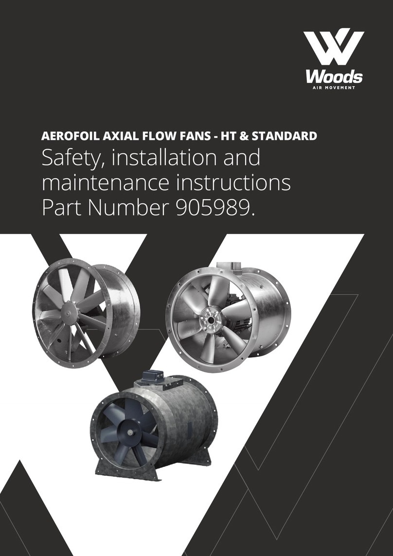
Woods EC-ITF User manual

EC INDUCTION THRUST FAN
Installation guide &
technical specications
(EC-ITF)

CONTENTS PAGE
1. INTRODUCTION ............................................................................................................................................................. 3
2. DESCRIPTION OF MACHINE ......................................................................................................................................... 4
3. INTENDED USAGE .......................................................................................................................................................... 5
4. INTENDED VIEW OF SAFETY PRECAUTIONS .............................................................................................................. 6
5. TRANSPORT AND STORAGE ......................................................................................................................................... 7
6. INSTALLATION / ASSEMBLY .......................................................................................................................................... 8
7. IMPEMENTATION ........................................................................................................................................................... 11
8. MAINTENANCE AND REPAIRS ...................................................................................................................................... 12
9. OPERATIONAL FAILURE ................................................................................................................................................. 14
10. CONNECTION DIAGRAM ............................................................................................................................................. 15
11. CE & UKCA MARKING .................................................................................................................................................... 16
2
As this unit / motor is used a safety product and, in many cases, a certicated safety product
in S1/S2 use special attention is required to the installation and maintenance of this product.
It is strongly advised to have a well-programmed installation and maintenance, especially of
the electric motors, summed up as a periodical inspection (daily, weekly, monthly etc.).
ATTENTION!!
In case of changes to the machinery which have not been reconciled with the manufacturer
or in case of removal of the original type plate / CE-marking of the ventilation unit the CE
declaration will lose its validity and the manufacturer’s warranty will immediately expire.

1. INTRODUCTION
The safety precautions regarding possible (life-threatening) personal injury are designated
in the margins with this symbol.
You will nd this symbol in places in the manual where important instructions are given for
the proper operational methods for preventing damage or malfunctioning of the fan unit.
The fan units which Woods Air Movement supplies are of the utmost modernity and meet all safety regulations of
the EC machine guideline 2006/42/EC, EMC guideline 2006/95/EC/EG and low voltage guideline 2004/108/EC.
However, any fan unit can present a danger if:
- the fan unit is not installed, serviced or maintained by personnel especially trained for this purpose,
- the fan unit is not used in accordance with the guidelines.
In this case you will be posing danger of (fatal) injury to personnel and may cause damage to materials and
buildings, besides reducing the fan’s eciency.
This manual must be read and followed by anyone wishing to use the fan unit.
This manual:
- Describes proper use of the fan unit of type:
• EC-ITF©, and warns against improper usage (Point 3),
- contains safety precautions which must be strictly adhered to (Point 4),
- contains warnings against possible dangers which may arise, even in the case that the precautions are followed
- contains important instructions for safe usage of the fan unit,
- must be lled in with the relevant (national) regulations and standards.
Woods Air Movement bears no liability for damage or operational faults arising from non-compliance with the
instructions contained in this manual.
In the case of modications carried out on the fan unit without prior written approval from the manufacturer or
in the case of removal of the fan unit’s original type plate/CE designation, both the CE designation as well as the
manufacturer’s guarantee shall become immediately void.
Woods Air Movement bears no liability for consequential damage.
3

2. DESCRIPTION OF MACHINE
2.1. PRODUCT DESCRIPTION
Parking garage fan units from the EC-ITF©series with unilateral extraction have been developed for a room in a
building whereby, in the case that air pollution is present, a directional air ow can be initiated through which the
polluted air (cold smoke, etc.) can be extracted from the room.
The air is drawn up by via the grate through the motor/impeller combination and blown out via the outow
opening.
The fan unit is equipped with two backward inclined impellers each with an integrated EC, external rotor motor.
The applied EC motors are IP 54, ISO B, S1. The connection voltage is 200~240/1/50/60. The power supply
connection is through an outer terminal box (OTB1) and the speed control including maximum airow connection
is also through another outer terminal box (OTB2). The fan must always be properly grounded.
The fan unit is intended for installation on a ceiling/wall whereby it is not permitted to have
the fan unit arranged (vertically) blowing out upwards. Safety precautions must comply with
the requirements contained in EN 292.
2.2. TECHNICAL SPECIFICATIONS
The technical specications and permissible boundary values are contained in the technical specications sheet.
These values may not be exceeded.
4

3. INTENDED USAGE
3.1. INTENDED USAGE
The fan units are intended for extraction/conveyance of clean and slightly polluted air and other, non-aggressive
gasses or fumes (with a temperature range of -20° C to 50° C in the standard operational situation).
Any usage deviating from that stated above is not permitted; Woods Air Movement bears
no liability for any personal or material damage resulting from such deviation! The validity
of the CE designation shall likewise expire.
In the case that regulating equipment with electronic components (such as frequency modulators) is used,
the manufacturer’s recommendations must be complied with (for example: grounding, cable lengths,
cable guards, etc.)
3.2. UNINTENDED USAGE
Improper usage includes, but is not limited to, the transfer of:
- gasses and fumes with a temperature higher or lower than the prescribed temperature,
- aggressive gasses or fumes,
- gasses or fumes with a high dust content.
Possible results:
corrosion damage, equilibrium loss, vibration, deformation, damage from tear.
Possible dangers:
Personal or material damage due to impeller fracture, shaft fracture, fatigue fracture or re
resulting from spark formation.
The fan units from the EC-ITF© standard series are not to be integrated into any area where danger of explosion
is present.
5

6
4. GENERAL SAFETY PRECAUTIONS
- Always read through these safety instructions with care and be sure to follow them,
- electricity must be turned o before you can begin cleaning or maintenance work (see Point 8),
- maintenance work on the fan unit must be carried out by a technically qualied professional, contact the
supplier to do so,
- safety precautions have been created for each operation, such as;
- installation,
- electrical connection,
- implementation
- maintenance and repairs,
- never use the fan unit for applications that it is not designed for,
- use electrical cables which are suitable for the maximum motor load,
- the operator/assembler/installer must be conscious of the fan unit’s safe operation before beginning
maintenance work,
- safety guards and similar which are removed or disassembled for installation or maintenance work must be
returned to their proper position after the installation or maintenance work and before reconnection to the
power supply.
- before using the fan unit, check to see that all safety guards are properly installed and/or the fan unit can
function properly. When in doubt, do not take any chances; call for the supplier,
- turning the fan unit on and o must always be done with care (see Point 7),
- never overload the fan unit (see Point 7),
- when an abnormality appears, such as excessive vibration or noise, turn the fan unit o immediately.
- always wear protective clothing when working on the fan unit,
- for questions or doubts regarding the safe operation of the fan unit, always contact the supplier.

7
5. TRANSPORT
5.1. TRANSPORT DAMAGE
You must immediately check the shipment to make sure it is undamaged and complete and must do so in
the presence of the supplier. In the case of transport damage, contact the service department for advice (see
contents).
The fan units can be shipped in their original packaging (on 1 pallet and plastic-wrapped).
The fan units must be transported in accordance with the applicable guidelines/standards.
Unprofessional transport such as setting the product down too hard or on its side can lead to:
- the impeller becoming jammed in the fan unit or being thrown o balance,
- misaligning of the shafts,
- damage to the bearings,
- damage to electrical components,
- damage to the paint.
5.2. TRANSPORT SAFETY
The transport device must be suitable for lifting the weight of the pallet (meaning the fan units plus packaging).
The fan units can be shipped in their original packaging (on 1 pallet and plastic-wrapped). Once on location,
position the units as close as possible to the place where they will be installed.
The following can act as leverage points for the fan unit:
1. Pallet (if still in original packaging)
2. Mounting plate
No other options for lifting the product are permitted.
The following leverage points are unsuitable:
- packaging
- the grid
- the fan unit’s outlet opening,
- any operational switch, frequency regulator or outer terminal box that may be installed.
5.3. TEMPORARY STORAGE
For temporary storage of the fan unit, the following points must be strictly adhered to:
- Humidity 50% and temperature between 5º C and 60º C, free of dust, dirt, gasses and corrosive atmosphere
- It is recommended to store the fan not longer than 12 months after delivery
- Before installation check the motor bearing

8
6. ASSEMBLY / INSTALLATION
6.1. SAFETY PRECAUTIONS
- Assembly may be carried out only by technically qualied personnel, whereby this manual
and the applicable specications must be adhered to.
- Assemble the unit with the correct locking/torque wrench.
- Check the 4 mounting points with which the fan is secured to the ceiling/wall.
- Safety guards and similar which are disassembled for installation must be immediately returned
to their proper position after installation and before reconnection to the power supply.
- The fan units must be installed in such a way that their positioning and stability are always
guaranteed during operation.
6.2. SECURING THE UNIT
The mounting place, as regards conditions, must have ambient temperature and surrounding medium, be suitable
for the fan unit in question (see also Point 3)
The bearings may be damaged by pressure, causing fatigue fractures whereby the fan unit’s
operation may be obstructed.
Vibrations, increased power consumption and smoke are some of the possible results.
For this reason, no force should be applied to the fan unit via installation components. The ceiling must be at at
the places where the fan unit is secured.
6.3. ELECTRICAL CONNECTION
6.3.1. SAFETY PRECAUTIONS
The electrical installation of the fan unit and its components may only be carried out by specially
trained professionals, under compliance with this manual and applicable specications.
The following standards and guidelines must be adhered to:
• IEC 364/DIN VDE 0100 ; DIN 57105, part 1 / VDE 0105, part 1; EN 60204, part 1 / VDE 0113, part 1.
• Specications of the local energy company, EN 1010.
For protection against unexpected start-up, installations must be assembled in conformity with
EN 60204/DIN VDE-113 (such as lockable inspection switches).
6.3.2 MOTOR/MOTOR CONNECTION
The motor connection must take place in accordance with the attached connection diagram (see connection
diagram sheet).
The Installer must employ the appropriate safety category, which corresponds to valid Local norms, when carrying
out the electrical installation of the unit.

6.3.3 MOTOR PROTECTION
Fuses and contact breakers do not suce as motor protection. The manufacturer’s guarantee becomes void in the
case of damage as a result of insucient motor protection.
The EC motor protection is integrated in the motor electronics, be sure that in case a fault occurs, the EC motor can
not switch on again automatically after it has cooled down.
6.3.4 MOTOR START-UP
Motors can be turned on immediately. These motors have been developed for class S1 continuous processes.
The applicable capacity of the power utility in question must be conformed to in all cases.
In the case of pulsing operation, please contact the supplier.
6.4 INSTALLATION
- The locations where the units / motors are installed should be allowed easy access for inspection and
maintenance services. The supplier of the units / motors is not liable for removing units / motors from the site.
- Install cable glands to protect the main and accessories lead wires. Handle this leads carefully in order to avoid
insulation damages on leads and cable in general.
- Check carefully the leads, the special leads protection must be removed before connecting to ensure good
power supply.
- Bearings are sensitive to standstill vibration or impacts caused during handling. All units are balanced (and
tested) as per G4.0. It is important to handle the units during internal transport and mounting with care
otherwise it can cause unacceptable vibration.
- Check the specic lead connection diagram indicated on the main motor nameplate or the wiring diagram
attached to each unit, noting the correct lead indication.
- For power connection use only material that ensures excellent electrical conductivity.
- Unit / motor must be operated in accordance with the dened design duty.
9

10
7. IMPLEMENTATION
7.1. SAFETY CHECK
Check to see that all mechanisms and electrical protections are in place and connected.
The following checks must be made before the unit can be switched on:
Make sure that an uncontrolled start-up of the fan unit during implementation is impossible (such as with
a lockable work switch)!
7.1.2. BEFORE STARTING UP
- Turn the impeller/motor by hand to ensure free running of the impeller.
- Is the unit / motor/ impeller clean, free in- and outlet / no parts in the in- and outlet.
- Is the correct power supply (V/Ph/Hz) according the indication on the nameplate.
- Is the unit / motor mounted correctly and at on a ceiling without any torsion → correctly aligned.
- Make sure that all four bolts of the mounting plate of the unit are tightened rmly and correctly.
- Are the bearing lubricated correctly, also after long term storage.
- Is the motor / unit correctly grounded.
- Is the inlet air ventilation passing freely through the motor to ensure the cooling of the motor.
- Are all required unit/ motor protection on.
7.1.3 MAKE SURE THAT THE CONNECTED REGULATING EQUIPMENT IS FUNCTIONING
PROPERLY
The fan unit may only be switched on once all safety measures have been applied!
7.2. CARRY OUT CHECK WHEN COMMISSIONING AND RECORD RESULTS
IN THE COMMISSIONING REPORT.
Commissioning may only be carried out by qualied persons. Warranty claims can only be made if commissioning
work is carried out correctly and written evidence is provided.
Turn the fan unit on for a short time to check that the rotational direction of the impeller conforms to the
rotational direction given by the arrow on the fan unit. If the direction is wrong, the motor (under compliance
with the safety precautions) must be electrically reversed.

7.2.1 FIRST STARTING CHECK-UP / COMMISSIONING REPORT
- After the unit is switched on, the motors start an initialization, after a few seconds of the initialization the control
input is active. The unit can be switched on via the control input. Do the commissioning tests at maximum
speed, as soon as the commissioning tests are done switch o the unit via the control input.
- The unit / motor serial number, rpm, mounting power, voltage and current.
- Do a visual inspection on the unit / motor; - cleanliness; - terminal box/service switch; - leads cables;
- cable glands; - bolts; - ttings
- The type of start; DOL, soft starter, frequency inverter, etc…
- The voltage between phases and compare with the voltage on the nameplate the unit.
- The current in each phase and compare with current on the nameplate of the unit.
- The speed of the unit and compare it with the speed on the nameplate of the unit.
- The bearing temperature.
- The vibration of the unit / motor and the acceleration.
- Final condition → approved or not approved and who is responsible for the approving.
11
If some / one of above-mentioned variables does not meet standard specication(s) or
are out of supplier characteristics and recommendations, please inform the supplier
immediately and SWITCH OFF THE UNIT / MOTOR to avoid serious damage of unit. If this
information is not communicated with the supplier immediately the warranty terms may
be void.

12
8. MAINTENANCE AND REPAIRS
8.1. SAFETY PRECAUTIONS
Maintenance personnel will be faced with danger of personal (fatal) injury if these precautions
are not complied with.
Maintenance and repairs may be carried out only by technically qualied personnel, whereby this manual and
the applicable specications must be adhered to.
Take note of the following before maintenance work can begin on the fan unit:
All drive motor poles must be detached from the power supply!
The impeller must come to a complete stop!
Check the temperature of the fan unit’s exterior to prevent re!
Make sure that an uncontrolled start-up of the fan unit maintenance is impossible
(such as with a lockable work switch)!
Before beginning maintenance work, remove any damaging or dangerous rests which are in the fan unit as a result
of the medium, making sure to use the proper tools!
Assembly takes place in the reverse order of disassembly. For all bolt connections, it is necessary
to use a torque wrench, besides the usual locking agents (spring washers, etc.).
Reimplementation of the fan unit may only occur after all safety checks have been made in compliance with
chapter 7.
This excludes operations which may only be carried out when the fan unit is in operation, such as vibration
measurements. In these cases, the applicable safety and accident-prevention guidelines must still be adhered to.
8.2. MAINTENANCE ADVICE
Depending on the surroundings, we advise:
1st check 1 month after implementation, followed by preventative maintenance after a maximum of 6 months.
8.3. MOTOR / IMPELLER
If wear or soiling of the motor or impeller can be expected as a result of the medium used (i.e. corrosion, tears,
caking), the unit must be inspected and cleaned. Under normal conditions, the bearings have a life expectancy
of 40.000 hours. Replacement of the complete EC fan/motor unit must occur in consultation with the supplier.
Never use a high-pressure cleaner (steam cleaner) or pressurised air to clean the motor!

13
8.4. FAN HOUSING
Check (welding, corrosion, damage) internally via the impeller and outlet duct and inspection window.
Externally as well. Remove dirt/dust.
8.5. RESERVE COMPONENTS
Only original factory reserve components as stated in the components list may be used.
8.6. MOTOR MAINTENANCE
A check-up is advisable for the motor every 6 months, whereby special attention should be given to:
- Insulation resistance must be above 100 M ohms (R>100MΩ). If it is less than this value, then this motor must
be either repaired or replaced.
- It is strongly advised to have a well-programmed maintenance, especially of the electric motors, summed up as
a periodical inspection (daily, weekly, monthly, etc). These inspections must include checking procedure like;
- Cleanliness (motor ns, fan cover, casing, motor, grid, etc)
- Current and voltage
- Bearings / motor temperature
- Ambient temperature
- Vibration levels
- Seals conditions
- Casing conditions
- Grid / motor holder conditions
- Balancing conditions
- Noise especially, bearing noise
- Lubrication condition and useful life
- Connection condition
- Screw tightness in general (of unit, motor, service switch, etc…)
- Winding life of the motor
- Insulation resistance
- Drain condensed water, etc.
Woods Air Movement bears no liability for damage arising as a result of the use of components
which have not been supplied through the manufacturer.

14
9. OPERATIONAL FAILURE
Deviations from the fan unit’s normal operating condition (noise, vibrations, smoke, current strength) indicate a
fault in the fan unit and must be investigated immediately by maintenance personnel.
Long-term faults can lead to serious damage to the fan unit and installation components
and can result in personal injury!
If the maintenance personnel are unable to remedy the fault, you must contact the fan’s supplier.
Fault Possible Cause Remedy
Fan doesn’t turn, switch is on
Work switch is at “0” or the cables in the terminal
box are not connected properly
Turn the work switch to “1” or (properly)
connect the cables in the terminal box
Fan is not turning,
Switch is on,
Work switch is on / terminal is connected
a. There is no power supply or the control fuse is
defective
Check the power supply, fuses and connections
b. The motor protection is activated
The motor protection becomes activated
during ventilation or test works
Bearing is defective
Check the motor at max. run, check power supply,
check power consumption,
check the impeller’s rotation
Impeller is o balance
Ceiling is not at,
Damage to fan unit Check the impeller for foreign objects, level out
the attachment plate,
ascertain damage (call the supplier)
The fan turns but moves no or little air
a. Airow interrupted
Create a free air passage,
Clean the impeller,
Check the extraction and blow-out sides
b. Improper fan rotational direction Electrically reverse the motor to change the
rotational direction (change phase)
Vibrations in the fan
a. There is dirt/dust caked on the
impeller blades Clean the impeller
b. The impeller is damaged Contact the supplier
c. The impeller is o-balance Contact the supplier
Extreme noise level The bearing is defect, impeller is improperly
turning See corresponding fault
9.1. DIS- / ASSEMBLY
Disassembly takes place in the reverse order of assembly. For all bolt connections, it is necessary
to use a torque wrench, besides the usual locking agents (spring washers, etc.).
Reimplementation of the fan unit may only occur after all safety checks have been made in compliance with
chapter 7.

15
10. CONNECTION DIAGRAM
*Nothing may be removed, crossed out, duplicated, applied and/or copied from this sheet.
I
Attachment: Technical Specifications Sheet. EC-ITF
A. Connection diagram OTB – Power supply/Control Interface
Power supply 200~240/1/50/60
P11 = L Fan motor 1 &2
P12 = N
P13 = Earth
-------------------------------------------------- ---------------------------------------------------
Control interface
P21 = 10 Volt fan 1
P22 = 0-10 Volt fan 1 & 2
P23 = GND fan 1 & 2
P24 = Tacho fan 1 Fan motor 1 & 2
P25 = Tacho fan 2
P26 = 10 Volt fan 2
* Nothing may be removed, crossed out, duplicated, applied and/or copied from this sheet.

16
11. CE & UKCA MARKING
11.1 Declaration of Conformity
We hereby declare under our sole responsibility that Woods Air Movement products comply with the requirements
of the applicable UK and EC/EU directives.
The Declaration of Conformity for compliance with the applicable directives exclusively refers to fans that are
connected according to the operating instructions and operated independently with sinusoidal power supply.
The Declaration of Conformity for compliance with the ErP directive and associated regulations is only valid in
conjunction with the ErP-related data in the product information and nameplate.

17
Declaration of Conformity
As defined by the EC Machinery Directive 2006/42/EC.
Designation of the machine: Model or type of machine: Since year of manufacture:
Induction Thrust Fan EC – ITF 2020
EC Machine Guideline (2006/42/EC)
ErP Directive (2009/125/EU)
EC-EMC Guideline (2014/30/EU)
RoHS Guideline (2011/65/EU)
EN 60204-1 EN 12100-1 EN 12100-2 EN 61000-6-1
EN 61000-6-3
Herewith we declare that the machine
Meets the basic requirements of the guidelines:
The following harmonized standards are applied:
The specific technical documentation in accordance with Appendix VII B has been written and is available in
its entirety. The specific documentation will be transmitted to the official authorities on justified request through
electronic means, on data carriers or on paper.Name of representative for documentation:
Address of the nominated Person: see manufactures address
EC-declaration of Incorporation was issued:
Place, Date
Colchester, 10.10.2019
Simon Chapman
R&D Director Woods Air Movement
Manufacturer Woods Air Movement
Axial Way Colchester
CO4 5ZD, GB

Woods Air Movement delivers smart and energy
efficient Air Movement and Fire Safety solutions to
support every application area. We offer our customers
innovative technologies, high quality and outstanding
performance supported by more than fifty years of
accumulated industry application experience.
The widest range of Air Movement and Ventilation
products in the market, and strong market presence
with over 100 years of experience and manufacturing
of products, guarantees that we are always by your
side, ready to deliver Excellence in Solutions.
Contact our friendly sales team today
for more information
Call: +44 (0) 1206 222 555
Email: [email protected]
www.woodsairmovement.com
WAM_DC_00044GB_Woods EC-ITF_OM_20210927_R0_.pdf
Table of contents
Other Woods Fan manuals
Popular Fan manuals by other brands

BLAUBERG Ventilatoren
BLAUBERG Ventilatoren Iso-ZS user manual

Dimplex
Dimplex DCMIST25 instruction manual

Stadler Form
Stadler Form Charly operating instructions

mercor
mercor mcr-PROLIGHT DVP Operation and maintenance manual

Airflow
Airflow QuietAir QT 150B Installation and operating instructions

S&P
S&P PCD110X manual