Westell INTELIPORT I SDS5486LN User manual

Equipment Issue 4
030Ć101328 Rev. A , August 2002
Section SDSĆ548Ć6LNĆ204
R
0208I4RA
ECopyright 2002 Weste , Inc. A rights reserved. Printed in the United States of America.
*CLEI, CLLI, CLFI, and CLCI are trademarks of Te cordia Techno ogies.
200 Mechanicsr and INTELIPORTr are registered trademarks of Weste , Inc. Page 1 of 18
Westell INTELIPORTr I 2W/4W Data Station Termination
w/ Transmit Level Adjust and or 4ĆTone Alignment
Model SDS5486LN (Issue 4)
CLEI* Code: DST1KDN1AA
CONTENTS PAGE #
1. GENERAL 1. . . . . . . . . . . . . . . . . . . . . . . . . . . . . . . . . . . .
2. APPLICATIONS 2. . . . . . . . . . . . . . . . . . . . . . . . . . . . . . .
. CIRCUIT/FUNCTIONAL DESCRIPTION 2. . . . . . . . .
4. OPTIONS 8. . . . . . . . . . . . . . . . . . . . . . . . . . . . . . . . . . .
5. INSTALLATION 8. . . . . . . . . . . . . . . . . . . . . . . . . . . . . . .
6. TESTING & TROUBLESHOOTING 9. . . . . . . . . . . . . .
7. CUSTOMER & TECHNICAL SERVICES 16. . . . . . . .
8. WARRANTY & REPAIRS 16. . . . . . . . . . . . . . . . . . . . . .
9. SPECIFICATIONS 16. . . . . . . . . . . . . . . . . . . . . . . . . . . .
1. GENERAL
1.1 Document Purpose
This document describes the Westell INTELIPO Tr I Model
SDS5486LN Issue 4, shown in Figure 1.
Ć NOTE Ć
Hereafter, the Westell INTELIPORT I Model SDS5486LN IsĆ
sue 4 ill be referred to as the SDS5486LN" or the INTELIĆ
PORT."
1.2 Document Status
evision A of this practice replaces the 057Ć029600 with
030Ć101328 and updates the company contact information.
Whenever this practice is updated, the reason will be stated in
this paragraph.
1. Product Purpose and Description
Westell's INTELIPO T I, Model SDS5486LN Issue 4, provides
an interface between a 4Ćwire facility and a 2Ćwire or 4Ćwire data
modem. As a member of Westell's family of Intelligent Network
Channel Terminating Equipment (INCTE), the SDS5486LN
provides all the functions of a standard DST but with additional
features such as remote testing and alignment capability. The
SDS5486LN contains an onĆboard microprocessor and preciĆ
sion oscillator circuits. These circuits allow comprehensive
Figure 1. Front View of SDS5486LN
TEST
SDS5486LN ISS.4
XMT RCV FAIL ALIGN SC PWR
TEST LPBK
NTELiORT
P
I
remote alignment and testing of INTELIPO T when activated
from a Serving Test Center (STC).
1.4 Product Features
The SDS5486LN offers the following features.
SOperates in 2W or 4W applications.
SMicroprocessorĆcontrolled unit.
SPrecision oscillator generates test tones during testing
and alignment.
STerminating impedance option of 150, 600, or 1200 Ohms
to match the impedance of the 4Ćwire facility (switchĆseĆ
lectable).
Semote (manual) 3 or 4 tone alignment capability.

Section SDSĆ548Ć6LNĆ204 030Ć101328 Rev. A R
0208I4RA
2
SAutomatic 4Ćtone alignment capability; Auto Align is
activated via a frontĆpanel TEST switch during the first
five minutes of initial powerĆup or via command mode by
sending 1804 Hz to INTELIPO T.
SAutomatically adjusts amplitude response characteristics
(up to 15.3 dB, referenced at 1004 Hz) to meet C5 condiĆ
tioning requirements.
SUnit identification tone (alternating 1014 Hz/414 Hz)
identifies unit being accessed for maintenance testing as
INTELIPO T.
Semotely adjustable XMT OUT Level setting in 0.5 dB
(gain/loss) increments.
SFullĆrange transponder operation (300 to 3200 Hz) with
quiet termination permits remote testing of noise and
tone level measurements at TLP or DLP.
SFrontĆpanel TEST switch used to activate INTELIĆ
PO T's wire test mode for verifying station wiring.
SSealing current Supply/Off/Term operation.
SNonĆvolatile memory retains programmed information in
the event of power loss.
SMounts in one position of a Westell Type 550 (TypeĆ400
equivalent) or 200 Mechanicsr mounting.
SOperates from Ć22 to Ć56 Vdc at 95 mA maximum or
from 20 to 28 Vac at 115 mA maximum.
S7Ćyear warranty.
2. APPLICATIONS
The SDS5486LN provides an interface between a 4Ćwire facility
and a 600Ćohm 2W or 4W data modem. The SDS5486LN is norĆ
mally located on the same premises as the modem. The integral
microprocessor circuit controls all functions of the unit. The preĆ
cision oscillator circuit generates test tones during testing and
alignment.
2.1 Command Mode
INTELIPO T incorporates a command mode from which all
functions except manual and toneĆactivation of the loopback cirĆ
cuit are accessed. The command mode is the operational state
in which INTELIPO T monitors its transmission paths for inĆ
coming frequencies and interprets these frequencies as
commands to carry out specific functions. The command mode
is activated from the STC by sending 2713Hz for more than 30
seconds. INTELIPO T responds by sending 1014Hz indicating
command mode initiation. If the tone is present for more than
2.0 seconds but less than 30 seconds, INTELIPO T sends a
1Ćsecond alternating tone of 1014Hz/414Hz and enters the loopĆ
back mode of operation.
2.2 XMT OUT Level Adjust
The operating levels for Westell's SDS5486LN are given in
Table 1. The Transmit Out level can be remotely adjusted to acĆ
commodate any level from +7 to Ć16 dBm. The XMT OUT level
can be adjusted by adding either gain or loss in 0.5dB increments
or can be set to achieve a Ć16 dBm level (see paragraphs 3.13 thru
3.16).
PORT
LEVELS (IN DBM)
PORT TLP DLP
RCV IN +5 to Ć10 Ć8 to Ć23
RCV OUT Ć3 Ć16
XMT IN +13 0
XMT OUT +5 Ć8
*The XMT OUT level can be remotely adjusted for any level from +7 to Ć16 dBM (TLP) or Ć6 to
Ć29 dBM (DLP)
Table 1. Operating Levels
2. Alignment (Remote and Automatic)
The SDS5486LN features both remote and automatic alignment
capability.
2.3.1 Remote Alignment
The Serving Test Center (STC) can align the circuit to either
three tones or four tones.
Ć NOTE Ć
FourĆtone alignment allo s a more accurate alignment hen inĆ
terfacing long sections of loaded cable or a mixture of loaded and
nonĆloaded cable facilities.
2.3.2 Automatic 4Ćtone Alignment
AutoĆAlign is activated from onĆsite via the frontĆpanel TEST
switch, during the first five minutes of initial powerĆup. AutoĆ
Align is also activated via the command mode by sending 1804
Hz to INTELIPO T.
. CIRCUIT/FUNCTIONAL OPERATION
efer to Figure 2, SDS5486LN (Issue 4) Block Diagram.
.1 LED Status Indicators
INTELIPO T has six, frontĆpanel LEDs that provide a quick
visual indication of the units status and mode. Table 2 provides
a brief summary of the LED functions.

Section SDSĆ548Ć6LNĆ204
030Ć101328 Rev. A
R
0208I4RA 3
Figure 2. SDS5486LN (INTELIPORT) ISSUE 4 Block Diagram
X
S3–C
4W 4W
TR
TT
S2–D
S2–C
S2–A
S2–B
RT
RR DRR
DRT
2W 2W
MNLB
LB
S3–B
1
55
49
5
15
41
47
7
13 LB
FAIL/
TEST
SC
OSCILLATOR
414Hz
1014Hz
2814Hz
1814Hz
AUTOMATIC
XMT OUT
LEVEL
XMT XMT DATA
DETECTOR
SEALING
CURRENT
LB
TEK5
TEK6
23
21
MICROPROCESSOR
MLBG
GND
PWR 35
17
19
S1
SUPPLY
OFF
TERM
LPBK
AMP
S3–A
2W
4W
1200
600
150
150
600
1200
DTT
ALIGN/
LPBK
TEST
HYBRID
XMT OUT LEVEL
ADJUSTMENT
DETECTOR
2222Hz = GAIN
2111Hz = LOSS
2333Hz = –16dBm
ELECTRONIC
SWITCH
CIRCUITRY
TRANSPONDER
CIRCUITRY
FULL RANGE
(304Hz TO 3204Hz)
1200
600
150
150
600
1200
AUTOMATIC
POST
EQUALIZATION RCV LEVEL
CIRCUITRY
2713Hz
FILTER AND
DETECTOR
LB
RELAY
LB
X
DTR
POWER
SUPPLY
XMT
OUT
RCV DATA
DETECTOR

Section SDSĆ548Ć6LNĆ204 030Ć101328 Rev. A R
0208I4RA
4
LED
ON
OFF
FLAS ING
LED ON OFF FLAS ING
PWR Power App ied Power Not
App ied NA
SC Sea ing CurĆ
rent App ied
Sea ing CurĆ
rent Not ApĆ
p ied
NA
ALIGN/
LPBK
Command
Mode, A ignĆ
ment Mode or
Transponder
Mode
Id e Loopback
Mode
FAIL/
TEST
Logic Fai ure Id e Test Mode
XMT Receiving data
from EquipĆ
ment
Id e NA
RCV Transmitting
data to EquipĆ
ment
Id e NA
Table 2. Operating Levels LED Status Indicators
.2 Option Switches
The SDS5486LN contains three option switches that must be set
to the required position before the unit is installed. Option
switch S1 (Sealing Current) is used to select the appropriate
sealing current configuration (Supply/Off/Term). Option switch
S2 (Facility Impedance) is used to select the impedance of the
unit (150/600/1200 Ohms) that will match the impedance of the
4Ćwire facility. Option switch S3 (2W/4W) is used to set INTELIĆ
PO T's internal circuitry to properly interface the 2Ćwire or
4Ćwire data modem equipment.
. Unit Identification Tone
The SDS5486LN provides a unit identification feature that alĆ
lows the Test Center to verify which unit is being accessed. Upon
receiving 2713 Hz for more than two seconds, INTELIPO T
outputs an I.D. tone (one second of alternating 1014Hz/414 Hz)
identifying the circuit being accessed as Westell's INTELIPO T
I, Model SDS5486LN (Issue 4). At this point, if the 2713 Hz tone
is removed in less than 30 seconds INTELIPO T enters loopĆ
back. If 2713 Hz is applied for more than 30 seconds,
INTELIPO T enters command mode.
.4 Command Mode
As mentioned, the command mode is activated by sending
2713Hz via the CV IN port ( T and , pins 7 and 13, respecĆ
tively) for more than 30 seconds. NOTE: If 2713Hz is removed
in less than 30 seconds, INTELIPO T sends a 1Ćsecond alterĆ
nating tone of 1014Hz/414Hz and enters loopback.
Upon detecting 2713Hz for more than 30 seconds, INTELIĆ
PO T enters the command mode and returns a steady 1014Hz
tone at +5 dBm (TLP) via the XMT OUT port (TT and T , pins
41 and 47, respectively) indicating command mode initiation.
STC, at this point, removes the 2713Hz tone being sent to INTEĆ
LIPO T.
While in command mode, the STC can activate INTELIPO T's
intelligent functions which include: XMT OUT Level Adjust
mode, remote alignment mode, TLP or DLP Quiet Term/TransĆ
ponder mode or the STC can exit the command mode and return
to idle.
Ć NOTE Ć
The command mode is equipped ith a 5Ćmin timer circuit.
If no tone is sent to INTELIPORT during the five minute time
frame, INTELIPORT sends an error tone (rampĆdo n tone
from 3014 Hz to 314 Hz; holding 314 Hz for 10 seconds) and
returns to idle. The rampĆdo n tone, in this case, indicates the
command mode has timed out via the 5Ćmin timeĆout feature.
.
.5 Alignment Mode
INTELIPO T features both remote and automatic alignment
capability. emote alignment is used to align INTELIPO T
from the STC. Alignment is done at TLP and with respect to eiĆ
ther three tones or four tones. AutoĆAlign is used to
automatically align INTELIPO T with an intelligent ETO at
the near end (ISQ4389LNI2 or AUA441LN). AutoĆAlign is also
done at TLP and with respect to four tones. Please note, howevĆ
er, that the autoĆalign feature is only initiated by pressing the
frontĆpanel TEST switch for more than five seconds and only
during the first five minutes of initial powerĆup. AutoĆAlign is
also activated from command mode by sending 1804Hz to INĆ
TELIPO T.
.6 AutoĆAlign
As mentioned, AutoĆAlign is initiated during the first five minĆ
utes of initial powerĆup by pressing the frontĆpanel TEST switch
for more than five seconds or from command mode by sending
1804Hz to INTELIPO T. Upon initiating AutoĆalign mode, INĆ
TELIPO T then sends 2913Hz out the CV IN port (pins 7,13)
to the near end ETO. Upon entering command mode, the ETO
will then return 1014Hz to INTELIPO T.
When 1014Hz is detected from the near end, INTELIPO T
sends 1014Hz. Upon detecting 1014Hz from INTELIPO T, the
near end returns 2814Hz. Upon detecting 2814Hz from the near
end, INTELIPO T sends 2814Hz. Upon detecting 2814Hz
from INTELIPO T, the near end returns 414Hz. Upon detectĆ
ing 414Hz from the near end, INTELIPO T sends 414Hz.
At this point, if the near end has the capability of aligning to four
tones, the near end, upon detecting 414Hz from INTELIPO T,
returns 1814Hz to INTELIPO T. Upon detecting 1814Hz, INĆ
TELIPO T sends 1814Hz. Upon detecting 1814Hz from
INTELIPO T, both ends align to four tones.
Upon completion of alignment (approximately two to three
minutes), INTELIPO T returns to idle. The near end also reĆ
turns to idle.

Section SDSĆ548Ć6LNĆ204
030Ć101328 Rev. A
R
0208I4RA 5
.7 Remote (Manual) Alignment
While in command mode (1014Hz present), the STC should
verify/record the level received. The STC then initiates manual
alignment by sending 1004Hz to INTELIPO T. Upon detecting
1004Hz, INTELIPO T returns 2814Hz. The STC should verify/
record the level received at 2814Hz, then sends 2804Hz to
INTELIPO T. Upon detecting 2804Hz, INTELIPO T returns
414Hz. The STC should verify/record the level received at
414Hz, then sends 404Hz. Upon detecting 404Hz, INTELIĆ
PO T returns 1814Hz for 120 seconds. The STC should
verify/record the level received at 1814Hz, then has the option
of aligning the circuit to 3 tones or 4 tones.
Ć NOTE Ć
INTELIPORT provides a builtĆin five minute aiting period for
each tone (1004, 2804, and 404Hz) to be returned by the STC.
If no tone is sent to INTELIPORT during the 5Ćmin time frame,
INTELIPORT sends an error tone (rampĆdo n tone of 3014Hz
to 314Hz; holding the 314Hz tone for 10 seconds) and returns to
idle. The rampĆdo n tone, in this case, indicates the remote
alignment mode has timed out via the 5Ćmin timeĆout feature.
.8 ĆTone Alignment
If a 3Ćtone alignment is required, the STC ignores the 1814Hz
tone from INTELIPO T. After 120 seconds, the 1814Hz tone
times out, INTELIPO T sets the alignment levels, sends a eiĆ
ther a rampĆup or rampĆdown tone (see paragraph 3.10), applies
a quiet termination for approximately one second, then enters
loopback (see paragraph 3.11). NOTE: The 120Ćsecond timer
can be bypassed by sending 1004Hz to INTELIPO T during the
120Ćsecond time frame.
.9 4ĆTone Alignment
If a 4Ćtone alignment is required, the STC sends 1804Hz within
the 120Ćsecond time frame to INTELIPO T. Upon detecting
1804Hz, INTELIPO T aligns to four tones, sends either a
rampĆup or rampĆdown tone (see paragraph 3.10), applies a
quiet termination for approximately one second, then enters
loopback (see paragraph 3.11).
Upon completing the alignment, INTELIPO T automatically
outputs a level of +5 dBm (TLP) immediately following the
alignment process. If a level other than +5 dBm (TLP) is reĆ
quired, see paragraphs 3.13 thru 3.16 for details on adjusting the
XMT OUT level.
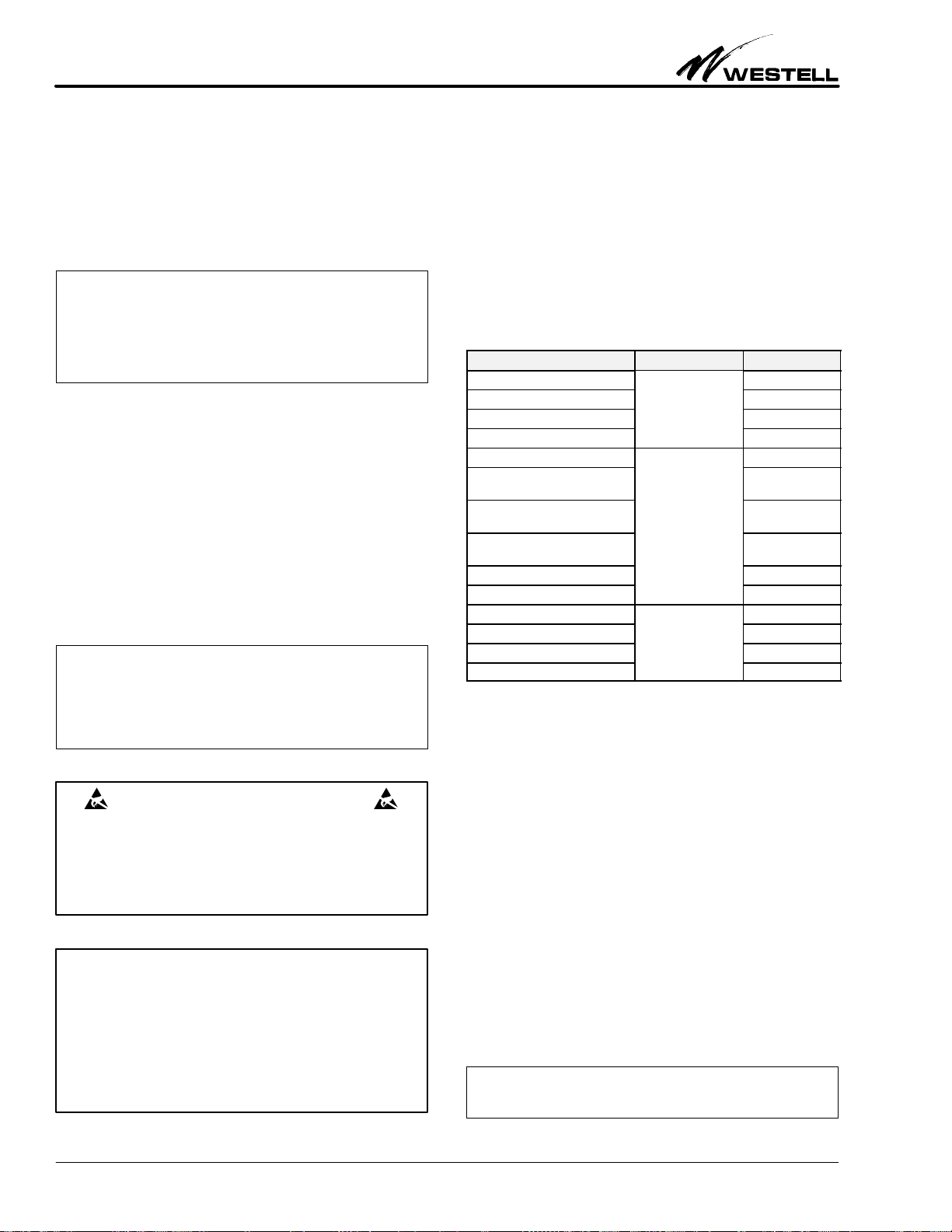
.10 RampĆUp/RampĆDown Tone
The rampĆup tone, consisting of a series of tones ranging from
314Hz to 3014Hz in ascending order, indicates alignment is
within the requirements of C5 conditioning. The rampĆup tone
also occurs whenever a 20Ćminute timer circuit times out due to
inactivity (that is, no tone sent to INTELIPO T during a test
function equipped with the 20Ćminute timeĆout feature). The
rampĆdown tone, consisting of a series of tones ranging from
3014Hz to 314Hz in descending order, indicates alignment is not
within the requirements of C5 conditioning. The rampĆdown
tone also occurs whenever a 5Ćminute timer circuit times out due
to inactivity (that is, no tone sent to INTELIPO T during a test
function equipped with the 5Ćminute timeĆout feature).
The rampĆup or rampĆdown tone sequence is applied for
approximately three seconds with the last tone (3014Hz in the
rampĆup sequence or 314Hz in the rampĆdown sequence) being
applied for approximately 10 seconds.
.11 Loopback
Loopback permits verification of alignment settings. While in
loopback, the STC sends tones (404, 1004, 1804 and 2804Hz),
one at a time, to INTELIPO T. The STC should verify/record
the level of each tone as it is looped back by INTELIPO T. The
loopback circuit automatically inserts 16dB of gain to provide an
equalĆlevel loopback condition for verifying alignment settings.
Ć NOTE Ć
Loopback can be toneĆactivated from the idle state by sending
2713 Hz for more than t o seconds but less than 30 seconds.
Loopback can also be activated manually by placing a ground
on the MNLB lead, pin 1.
.12 Loopback Release
Loopback is equipped with a 20Ćminute timeĆout feature that
automatically releases the loopback condition 20 minutes after
initial activation.
When loopback is entered after the alignment mode and if reĆ
lease from loopback is desired before the 20Ćminute time frame,
the STC can send 2713Hz for 0.9 seconds, minimum. INTELIĆ
PO T returns to command mode. At this point, if the STC
removes and resends a second 2713Hz tone, INTELIPO T reĆ
turns to idle.
When loopback is entered from an idle state, release from loopĆ
back is accomplished by sending 2713Hz for 0.9 seconds,
minimum. INTELIPO T returns to idle upon detecting
2713Hz.
Ć NOTE Ć
When loopback is manually activated, neither automatic time
out nor detection of 2713 Hz ill effect loopback release. Release
of a manuallyĆactivated, neither automatic time out nor detecĆ
tion of 2713 Hz ill effect loopback release. Release of a manualĆ
lyĆactivated loopback condition can only occur by removing the
ground.
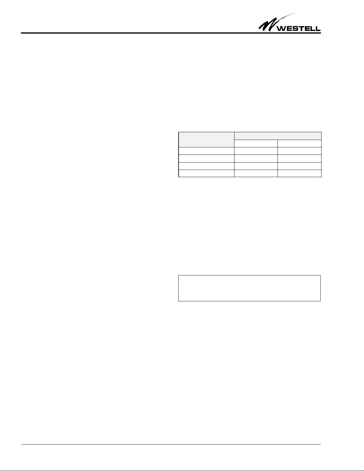
.1 XMT OUT Level Adjust Mode
INTELIPO T's operating levels are factory set for Ć3.0 dBm at
the CV OUT port, +13.0 dBm at the XMT IN port, and
+5.0dBm at the XMT OUT port (refer to Table 1). The XMT

Section SDSĆ548Ć6LNĆ204 030Ć101328 Rev. A R
0208I4RA
6
OUT level, however, can be adjusted for any level from
+7.0dBm to Ć16.0dBm TLP (Ć6.0 to Ć29.0dBm DLP). The XMT
OUT level can be adjusted by adding either gain or loss, in 0.5dB
increments, to obtain the desired transmit output level. To acĆ
cess the XMT OUT Level Adjust mode, the STC sends 1704Hz
while INTELIPO T is in the command mode. The STC can
monitor the XMT OUT port to verify the change in levels.
Ć NOTE Ć
INTELIPORT's XMT OUT Level Adjust mode provides a builtĆ
in five minute aiting period for each tone to be returned by the
STC. If no tone is sent to INTELIPORT during the five minute
time frame, INTELIPORT sends an error tone (rampĆdo n
tone of 3014 Hz to 314 Hz; holding the 314 Hz tone for 10 secĆ
onds) and returned to idle. The rampĆdo n tone, in this case, inĆ
dicates the XMT OUT Level Adjust mode has timed out via the
5Ćminute timeĆout feature.
.14 Adding Gain
The STC adds gain to the XMT OUT level by sending and reĆ
moving a tone of 2222Hz. Upon detecting 2222Hz,
INTELIPO T reĆadjusts the output level by adding 0.5dB of
gain. If more gain is required, the STC repeats the process of
sending and removing 2222Hz. INTELIPO T reĆadjusts the
output level by 0.5dB each time 2222Hz is sent and removed. AfĆ
ter obtaining the required XMT OUT level, the STC must send
2713Hz for 0.9 seconds minimum to return to command mode.
.15 Adding Loss
The STC adds loss to the XMT OUT level by sending and reĆ
moving a tone of 2111Hz. Upon detecting 2111Hz,
INTELIPO T reĆadjusts the output level by adding 0.5dB of
loss. If more loss is required, the STC repeats the process of
sending and removing 2111Hz. INTELIPO T reĆadjusts the
output level by 0.5dB each time 2111Hz is sent and removed. AfĆ
ter obtaining the required XMT OUT level, the STC must send
2713Hz for 0.9 seconds minimum to return to command mode.
.16 Ć16dBm Level
If desired, the STC can set the XMT OUT level for Ć16dBm by
sending and removing a oneĆtime tone of 2333Hz. Upon detectĆ
ing 2333Hz, INTELIPO T reĆadjusts its output level to
Ć16.0dBm. From this point, the STC can add gain to obtain the
desired XMT OUT level (see paragraph 3.13 and 3.14 above).
After obtaining the required XMT OUT level, the STC must
send 2713Hz for 0.9 seconds minimum to return to command
mode.
.17 Quiet Term/Transponder Operation
INTELIPO T's Quiet Term/Transponder operation allows the
STC to remotely conduct noise and tone level measurements.
The Quiet Term/Transponder test can be conducted with levels
referenced at either TLP or DLP (data level). In the TLP mode,
INTELIPO T outputs its respective tones at +5dBm (TLP) or
at the current XMT OUT level established via the XMT OUT
Level Adjust mode. In the DLP mode, INTELIPO T outputs
its respective tones at Ć8dBm (DLP) or at the current XMT OUT
level established via the XMT OUT Level Adjust mode.
To activate the TLP Quiet Term/Transponder, the STC sends
804Hz while in command mode. To activate the DLP Quiet
Term/Transponder, the STC sends 1304Hz while in command
mode. Upon detecting 804Hz or 1304Hz, INTELIPO T applies
a quiet termination over the XMT IN port and sets a 20Ćminute
timer circuit. During quiet termination, STC performs noise
measurements at the CV OUT port.
Ć NOTE Ć
Quiet termination remains in effect for 20 minutes or until
another tone (that is, to enter the transponder mode or return
to command mode) is sent to INTELIPORT. If no tone is sent
ithin the 20Ćminute time frame, INTELIPORT, after 20 minĆ
utes, sends a rampĆup tone (314 Hz to 3014 Hz; holding 3014
Hz for 10 seconds), then returns to idle. The rampĆup tone indiĆ
cates the Quiet Term/Transponder mode has timed out via the
20Ćminute timeĆout feature.
.18 FullĆRange Transponder Mode
The fullĆrange transponder mode allows the STC to perform a
detailed level verification test over a range of frequencies from
304Hz to 3204Hz. The fullĆrange transponder is accessed from
the quiet termination mode only by sending any tone from
300Hz to 3200Hz (except 2700Hz) to INTELIPO T. Upon deĆ
tecting tone from the STC, INTELIPO T responds by
returning a similar tone (at a 10Hz offĆset) for the same duration
tone is received from the STC. Tones sent by the STC should be
in increments of 100Hz. The STC should also verify/record the
level of each tone as it is returned by INTELIPO T. Each time
a new tone is sent, INTELIPO T responds to that tone. If no
tone is sent to INTELIPO T (i.e., after removing a tone), INĆ
TELIPO T reĆapplies a quiet termination and reĆsets the
20Ćminute timeĆout circuit.

Section SDSĆ548Ć6LNĆ204
030Ć101328 Rev. A
R
0208I4RA 7
S3
S2
1506001200
2W
4W
SUPPLY OFF TERM
S1
TEST
TEST
SDS5486LN ISS.4
XMT RCV FAIL ALIGN SC PWR
TEST LPBK
NTELiORT
P
I
OPTION
POSITION
FUNCTION
OPTION
POSITION
FUNCTION
SUPPLY Se ect to have unit supp y 20MA of sea ing current to simp ex eads
S1
OFF Se ect to disab e interna sea ing current circuit
S1
TERM Se ect to have unit provide termination for sea ing current supp ied from disĆ
tant end
1200 Se ect when interfacing oaded cab e faci ity
S2 600 Se ect when interfacing short nonĆ oaded cab e faci ity
S2
150 Se ect when interfacing ong nonĆ oaded cab e faci ity
S3
2W Se ect when interfacing 2W data modem equipment
S3 4W Se ect when interfacing 4W data modem equipment
TEST
PRESS (LESS THAN 5 SEC.) Press for ess than 5 seconds to activate INTELIPORT's Wire Test Mode.
Press for a second time to end the Wire Test Mode.
Note: The Wire Test Mode automatica y times out one hour after initia acĆ
tivation if the TEST switch is not pressed a second time.
TEST
PRESS (MORE THAN 5 SEC.) Press for more than 5 seconds to activate INTELIPORT AUTOĆALIGN seĆ
quence from onĆsite. (NOTE: This feature is activated on y during the first five
minutes of initia powerĆup of the unit.)
Table . SDS5486LN Switch Options
Upon completion if no tone is sent during the 20Ćminute time
frame, INTELIPO T, after 20 minutes, sends a rampĆup tone,
drops out of the Quiet Term/Transponder mode and returns to
idle. If release is desired before the 20Ćminute time frame, send
2713Hz for 0.9 seconds minimum to return to command mode.
Detection of a second 2713Hz tone causes INTELIPO T to reĆ
turn to idle.
.19 Sealing Current
Sealing current is recommended on all metallic facilities to help
prevent transmission path noise. Sealing current is a lowĆvalue
dc current (approximately 20mA) applied to the 4Ćwire dry cable
pairs on a simplex basis to break down resistance, which may
build up at nonĆsoldered cable splices. Continuous application
of sealing current helps prevent degradation of transmission
performance.
The internal Sealing Current circuit is controlled by option
switch S1. Switch S1 can be set to have the unit supply 20mA of
balanced sealing current to the facility's simplex leads (SUPĆ
PLY), provide a termination for sealing current supplied from
the distant end (TE M), or can be disabled (OFF) if sealing curĆ
rent is not required. NOTE: When sealing current is being
supplied from the unit, the simplex leads at the distant end must
be connected together to complete the path. Please also note
that when INTELIPO T is supplying sealing current, a 24 Vac
or Ć24 Vdc power source is adequate for a metallic facility loop
of less than 1000 Ohms. For loops in excess of 1000 Ohms, a Ć48
Vdc power source is recommended.

Section SDSĆ548Ć6LNĆ204 030Ć101328 Rev. A R
0208I4RA
8
4. OPTIONS
Westell's SDS5486LN provides three option switches that are
used to condition the module for proper operation in a given apĆ
plication. efer to Table 3 for the location and description of
each option.
Ć NOTE Ć
The TEST s itch, hen pressed for less than five seconds, actiĆ
vates INTELIPORT's ire test mode for verifying station iring.
This s itch is also used to activate INTELIPORT's automatic
alignment mode, from onĆsite, hen pressed for more than five
seconds. AutoĆAlign is activated only during the first five minutes
of initial po erĆup of the unit.
5. INSTALLATION
This section covers the physical installation of the SDS5486LN.
Installation consists of inspecting the equipment for damages,
following proper safety precautions, mounting the units in the
proper slot of the mounting assembly, or in a rack/on a wall), verĆ
ifying the presence of power and signalling as indicated by the
status LEDs.
Ć INSPECTION NOTE Ć
If not previously inspected at the time of delivery, visually inspect
the unit for damages prior to installation. If the equipment has
been damaged in transit, immediately report the extent of the
damage to the transportation company and to Westell (see Part
6 for telephone number).
CAUTION Ć STATICĆSENSITIVE
This product contains staticĆsensitive components! Proper
electrostatic discharge procedures must be followed to
maintain personal and equipment safety. Do not store units
near magnetic, electromagnetic or electrostatic fields. Always
store or ship units in the original staticĆprotective packaging
from Westell. Use antiĆstatic mats when working on units.
Ć PRECAUTIONARY STATEMENT Ć
Never install telephone wiring during a lightning storm.
Never install telephone jacks in wet locations unless the jack
is specifically designed for wet locations.
Never touch uninsulated telephone wires or terminals unless
the telephone line has been disconnected at the network
interface.
Use caution when installing or modifying telephone lines.
5.1 Installer Connections
When installing the unit in Westell's preĆwired USA TypeĆ550
mounting (TypeĆ400 equivalent), connections are made via
25Ćpair cables mating to the appropriate 25Ćpair cable connecĆ
tors located on the rear of the shelf assembly. When installing
the unit in Westell's unĆwired TypeĆ550 mounting (also TypeĆ400
equivalent), connections are made by wireĆwrapping the apĆ
propriate leads from the facility and data modem equipment to
the proper pins of the appropriate 56Ćpin connector that is loĆ
cated on the rear of the shelf assembly. Pin identifications for
proper wiring are listed in Table 4.
DESCRIPTION
PIN
DESCRIPTION PIN
RTĆRCV IN Tip 7
RR Ć RCV IN Ring
Faci ity
13
TT Ć XMT OUT Tip Faci ity 41
TR Ć XMT OUT Ring 47
DRT Ć Data RCV OUT Tip 5
DRR Ć Data RCV OUT
Ring
15
DTT Ć Data XMT IN/2W
Tip E
q
ui
p
ment
55
DTR Ć Data XMT IN/2W
Ring
Equipment
49
TEK5 23
TEK6 21
MNLB 1
MLBG
Misce aneous
19
PWR Misce aneous 35
GND 17
Table 4. Installer Connections
5.2 Power
Power requirement for proper operation is Ć22 to Ć56 Vdc (Ć48V
nominal) at 85 mA, or 20 to 28 Vac (24 V nominal) at 95 mA.
5. Wire Test Mode
Once the installer connections are complete, the option switches
have been set, and the unit is installed (see Section 4 Ć OPĆ
TIONS), the installer should activate INTELIPO T's Wire Test
mode to verify installation and station wiring. Momentarily
pressing the frontĆpanel TEST switch (less than five seconds)
causes 1014Hz to be applied to the CV and XMT transmission
pairs. Station wiring is verified by connecting a Transmission
Test Set with a builtĆin speaker or other suitable listening device
to the CV and XMT channel pairs at the cable connection and
demarcation points, and listening for the appropriate tones (see
Table 5). Once the tones are verified, the installer may press the
TEST switch again to end the test mode.
Ć NOTE Ć
The Wire Test mode automatically times out one hour after initial
activation if the TEST s itch is not pressed a second time.

Section SDSĆ548Ć6LNĆ204
030Ć101328 Rev. A
R
0208I4RA 9
PORT
4W APPLICAĆ 2W
PORT
4W
APPLICA
Ć
TIONS
2W
APPLICATIONS
RT Ć RCV continuous 1014
Hz
continuous 1014
Hz
RR Ć RCV
verify
continuous 1014
Hz
TT Ć XMT verify interrupted 1014
Hz
interrupted 1014
Hz
TR Ć XMT interrupted 1014
Hz
interrupted 1014
Hz
*In 2W applications, the RCV OUT and XMT IN ports utilize the same transmission pairs
XMT, IN, T and R pins 55 and 49).
Table 5. Wire Test Mode Tones
6. TESTING & TROUBLESHOOTING
6.1 Testing
Testing and alignment procedures (given in Table 6 through
Table 9) may be performed after the unit is installed and powĆ
ered up. The procedures outlined are intended only to ascertain
proper operation of the unit and, if problems should occur, to
isolate those problems to the most probable area. Testing conĆ
sists of performing the standard test procedures for digital
interface equipment using the KSĆ108/109 (or equivalent) reĆ
ceiver and transmitter data test sets. This equipment should not
be field repaired. If the equipment is suspected of being faulty,
replace it with another unit, optioned identically, and retest. If
the replacement unit appears to operate correctly, the original
unit may be faulty and should be returned to Westell for repair
or replacement (Paragraph 8.2).
6.2 Troubleshooting
If trouble is encountered, verify all installer connections to the
assembly and check that the CO power fuse is not blown. Also
verify all module connections and option switch settings, and
verify the modules are making a positive connection with the
shelf connector. If trouble persists, replace the suspect unit and
repeat procedures outlined. These procedures are not designed
to effect repairs or modifications. Any tests beyond those outĆ
lined herein, or repairs made beyond replacing a faulty unit, are
not recommended and may void the warranty.

Section SDSĆ548Ć6LNĆ204 030Ć101328 Rev. A R
0208I4RA
10
STEP
ACTION
STEP ACTION
INSTALLER'S PROCEDURES
1. Set option switches as required per Circuit Layout Record (CLR) card. Insta the unit and app y power. Verify PWR LED
ON SC LED ON (if app icab e) and ALIGN/LPBK FAIL/TEST RCV and XMT LEDs are OFF NOTE: If FAIL/TEST LED is
yyy
ON, SC LED ON (if app icab e), and ALIGN/LPBK, FAIL/TEST, RCV and XMT LEDs are OFF. NOTE: If FAIL/TEST LED is
f ashing, press frontĆpane TEST switch. If FAIL/TEST LED is ON steady, rep ace unit and repeat procedures.
Wire Test Mode
CAUTIONĆINTELIPORT p aces 1014Hz tone on the transmission pairs when TEST mode is activated. Be sure INTELIPORT
is not connected to an inĆservice circuit where this tone may cause interference.
Momentari
y
p
ress the frontĆ
p
ane TEST switch
(
ess than five seconds
)
and re ease. Verif
y
FAIL/TEST LED is f ashin
g
. ConĆ
2.
Momentari y
press
the
frontĆpane
TEST
switch
( ess
than
five
seconds)
and
re ease
.
Verify
FAIL/TEST
LED
is
f ashing
.
ConĆ
nect TMS with bui tĆin speaker, or other suitab e istening device, to:
PORT 4W APPLICATIONS 2W APPLICATIONS
RCV IN verify Continuous 1014 Hz Continuous 1014 Hz
RCV OUT verify Continuous 1014 Hz
XMT IN if I d H I d H
RCV
OUT verify Continuous
1014
Hz
XMT IN verify Interrupted 1014 Hz Interrupted 1014 Hz
XMT OUT verify Interrupted 1014 Hz Interrupted 1014 Hz
When tones are verified, press TEST switch to end test mode. Test mode automatica y times out one hour after initia acĆ
tivation if switch is not pressed a second time.
Note: In 2W app ications RCV OUT and XMT IN port uti ize same transmission pairs (XMT IN).
3
Serving Test Center's Procedures
Send 2713 Hz (>30 sec.*) at TLP to INTELIPORT's RCV IN port. Verify steady 1014 Hz at +5dBm (TLP) from INTELIPORT.
3.
Send
2713
Hz
(>30
sec
.
)
at
TLP
to
INTELIPORT s
RCV
IN
port
.
Verify
steady
1014
Hz
at
+5dBm
(TLP)
from
INTELIPORT
.
remove 2713 Hz. Command mode initiated.
Note: if 2713 Hz is present for two sec. but removed in ess than 30 seconds, INTELIPORT sends a 1Ćsecond a ternating
tone of 1014 Hz/414 Hz and enters oopback.
4
Remote (Manual) Alignment Mode
From command mode, verify/record eve received at 1014 Hz, then send 1004 Hz to INTELIPORT.
Upon detecting 1004 Hz, INTELIPORT returns 2814 Hz.
Verify/record eve received at 2814 Hz, then send 2804 Hz to INTELIPORT
Upon detecting 2804 Hz, INTELIPORT returns 414 Hz.
Verify/record eve received at 414 Hz, then send 404 Hz to INTELIPORT.
Upon detecting 404 Hz, INTELIPORT returns 1814 Hz for 120 seconds.
Verify/record eve received at 1814 Hz. At this point, STC has option of a igning to 3 tones or 4 tones.
3Ćtone a ignment: Ignore 1814 Hz tone. After 120 seconds, 11814 Hz tone from INTELIPORT times out.
INTELIPORT a igns to 3 tones, returns a rampĆup or rampĆdown tone*, app ies quiet termination for one second,
then enters oopback. NOTE: 120Ćsecond timer can be bypassed by sending 1004 Hz during the 120Ćsecond
time frame.
4Ćtone a ignment: Send 1804 Hz in response to INTELIPORT'S 1814 Hz in response to INTELIPORT's 1814 Hz
within the 120 time frame INTELIPORT a igns to 4 tones returns a ramp up or ramp down
*
app ies quiet
4. within the 120 time frame. INTELIPORT a igns to 4 tones, returns a rampĆup or rampĆdown*, app ies quiet
termination for one second, then enters oopback.
NOTE: Upon comp etion, if a eve other than +5dBm (TLP) is required at the XMT OUT port the STC shou d access the
XMT OUT Leve Adjust mode to set the desired output eve .
Note: RampĆup tone (314 Hz to 3014 Hz) indicates a ignment is within C5 conditioning. RampĆdown tone (3014 Hz to 314
Hz) indicates a ignment is not within C5 conditioning.
AutoĆAlign Mode
Note: AutoĆa ign is initiated by pressing the frontĆpane TEST switch (more than five seconds) during the first five minutes
of initia powerĆup, or via command mode by sending 1804 Hz to INTELIPORT.
When activated, INTELIPORT sends 2913 Hz out of the RCV IN port to near end to put near end into command mode.
Near end, upon entering command mode, returns command mode tone to INTELIPORT. With both Stations set, tones are
automatica y sent and received between both ends. Upon comp etion (approximate y two to three minutes), INTELIPORT
returns to id e. Near end a so returns to id e.
Table 6. Testing and Alignment Procedures

Section SDSĆ548Ć6LNĆ204
030Ć101328 Rev. A
R
0208I4RA 11
5. Loopback (After Alignment)
Upon entering oopback after a ignment, STC sends tones, one at a time, to INTELIPORT. Record eve of each tone as it is
ooped back by INTELIPORT.
Loopback is equipped with an automatic timeĆout feature that re eases oopback 20 minutes after activation. INTELIPORT
returns to id e. If re ease is desired before the 20Ćminute time frame, send 2713 Hz (0.9 sec, min.). INTELIPORT returns
to command mode. Remove and reĆsend 2713 Hz tone (0.9 sec, min.) to return to id e.
Loopback (From Idle State)
Send 2713 Hz for ore than two sec. but ess than 30 sec. Upon entering oopback, INTELIPORT returns a one second a terĆ
nating tone of 1014 Hz/414 Hz, identifying the unit accessed as Weste 's SDS5486LN, Issue 3. NOTE: At this point, if 2713
Hz is removed in ess than 30 seconds, INTELIPORT enters oopback. If 2713 Hz is app ied for more than 30 seconds,
INTELIPORT enters command mode.
6. XMT OUT Level Adjust Mode
Upon comp eting a ignment, the STC can adjust the XMT OUT eve for any eve from +7dBm to Ć16dBm (TLP), 0.5 dB
increments. STC can monitor the XMT OUT port to verify the change in the output eve . Whi e in command mode, send
1704 Hz to enter XMT OUT Leve Adjust mode. Once activated,
To add Gain: send and remove 2222 Hz. INTELIPORT reĆadjusts output eve by adding 0.5 dB of gains. If more gain is
required, repeat the process of sending and removing 2222 Hz unti desired output eve is obtained. INTELIPORT reĆ
adjusts the output eve by 0.5 dB each time 2222 Hz is detected and removed.
To add Loss: Send and remove 2111 Hz. INTELIPORT reĆadjusts output eve by adding 0.5 dB of oss. If more oss is
required, repeat the process of sending and removing 2111 Hz unti desired output eve is obtained. INTELIPORT reĆ
adjusts the output eve by 0.5 dB each time 2111 Hz is detected and removed.
To Set Level For Ć16 dBm: send and remove 2333 Hz. INTELIPORT reĆadjusts output eve to Ć16 dBm.
Upon comp etion, STC must send 2713 Hz (0.9 sec, min.) to return to command mode. A second 2713 Hz tone causes
INTELIPORT to return to id e.
NOTE: XMT OUT Leve Adjust mode is equipped with a 5Ćminute automatic timeĆout feature that re eases if no tone is sent
within 5 minute time frame. INTELIPORT returns to id e.
7. Transponder Mode (TLP/DLP)
From command mode, send 804Hz to access TLP Transponder or 1304 Hz, INTELIPORT app ies quiet termination over
the XMT IN port and sets a 20Ćminute timer. During quiet termination, STC performs noise measurements at the RCV OUT
port.
Whi e in quiet termination, the STC initiates the transponder mode by sending any tone from 300 Hz to 3200 Hz (except
2700 Hz), in 100 Hz increments. INTELIPORT returns simi ar tone (TLP or DLP) at a 10 Hz offĆset for same duration tone is
received.
Upon comp etion and if no other tone is sent, INTELIPORT reapp ies quiet termination and resets the timer circuit. If no
tone is sent within the 20Ćminute time frame, INTELIPORT, after 20 minutes, drops out of the transponder mode and returns
to id e. If re ease is desired before the 20Ćminute time frame, send 2713 Hz for 0.9 seconds, minimum. INTELIPORT REĆ
TURNS TO COMMAND MODE. A second 2713 Hz tone causes INTELIPORT to return to id e.
Table 6. Testing and Alignment Procedures (Continued)

Section SDSĆ548Ć6LNĆ204 030Ć101328 Rev. A R
0208I4RA
12
A
B
C
D
*
E
**
A B C D
*
E
**
COLUMN C MINUS
FREQUENCY
ALIGNMENT LEVELS
LOOPBACK LEVELS
COLUMN
C
MINUS
COLUM B
COLUMN D PLUS
Ć
16
FREQUENCY
ALIGNMENT
LEVELS
LOOPBACK
LEVELS
COLUM B
COLUMN
D
PLUS
Ć
16
1014 HZ
1014 HZ
2814 Hz
414 Hz
1814 Hz
*Co umn D equa s deviation from 0dBm (TLP)
**Co umn E equa s Customer's RCV OUT eve
Note: During this procedure, a tones from STC are sent at TLP.
1) Send 2713 Hz for more than 30 seconds. After detecting 2713 Hz for more than two seconds, INTELIPORT returns a 1Ćsecond,
a ternating tone of 1014 Hz/414 Hz (Unit I.D. tone) indicating the unit being accessed as Weste 's INTELIPORT 1, Mode
SDS5486LN.
2) After detecting 2713 Hz for more than 30 seconds, INTELIPORT sends 1014 Hz at +5 dBm (TLP). Record eve received in Co umn
B. Remove 2713 Hz. Command mode initiated. (NOTE: if XMT OUT eve requires adjustment it is accomp ished after comp eting
Steps 3 through 12. Procedures for adjusting XMT OUT eve is given on page 15, under Optiona Tests).
Remote Alignment Mode
3) Whi e in command mode, send 1004 Hz.
4) INTELIPORT returns 2814 Hz
5) Record eve at 2814 Hz in Co umn B, then send 2804 Hz
6) INTELIPORT returns 414 Hz.
7) Record eve at 414 Hz in Co umn B, then send 404 Hz
8) INTELIPORT returns 1814 Hz for 120Ćseconds.
9) Record eve at 1814 Hz in Co umn B. STC has option of a igning the circuit to either 3 tones or 4 tones:
3ĆTone A ignment Ignore 1814 Hz tone from INTELIPORT After 120 seconds*, 1814 Hz tone times out. INTELIPORT a igns to
3 tones, sends rampĆup or rampĆdown tone, then enters oopback. *NOTE: Send 1004 Hz within 120Ćsec.
time frame to bypass timer circuit..
4ĆTone A ignment Send 1804 within 120Ćsecond time frame. INTELIPORT a igns to 4 tones, sends Ćup or rampĆdown tone,
then enters oopback.
Loopback
10) Send 404 Hz. Record eve received from INTELIPORT in Co umn C.
11) Send 1004 Hz. Record eve received from INTELIPORT in Co umn C.
12) Send 2804 Hz. Record eve received from INTELIPORT in Co umn C.
13) (OPTIONAL) Send 1804 Hz. Record eve received from INTELIPORT in Co umn C.
14) Send 2713 Hz for 0.9 seconds. INTELIPORT returns to command mode. Remove 2713 Hz.
15) ReĆsend 2713 Hz 0.9 seconds. INTELIPORT returns to id e. Remove 2713 Hz.
16) Perform ca cu ations for Co umns D and E as required.
Table 7. SDS5486LN (INTELIPORT) ISSUE 4 ALIGNMENT

Section SDSĆ548Ć6LNĆ204
030Ć101328 Rev. A
R
0208I4RA 13
SDS5486LN OPTIONAL TESTS
XMT OUT LEVEL ADJUSTMENT
TO ADD GAIN
TO ADD LOSS
TO OBTAIN Ć16 dBm
TO ADD GAIN
TO
ADD
LOSS
TO
OBTAIN
Ć16
dB
m
1. From command mode, send 1704Hz 1. From command mode, send 1704Hz 1. From command mode, send 1704Hz
2. INTELIPORT sends 1014 Hz at +5
dBm (TLP)
2. INTELIPORT sends 1014 Hz at +5
dBm (TLP)
2. INTELIPORT sends 1014 Hz at +5
dBm (TLP)
3. STC sends and removes 2222 Hz 3. STC sends and removes 2111 Hz 3. STC sends and removes 2333 Hz
4. INTELIPORT adds 0.5 dB of gain to
output eve .
4. INTELIPORT adds 0.5 dB of gain to
output eve .
4. INTELIPORT reĆadjusts output eve
to Ć16 dBm (TLP).
5. Repeat Steps 3 and 4 unti desired
output eve is obtained.
5. Repeat Steps 3 and 4 unti desired
output eve is obtained.
5. Send 2713 Hz for 0.9 seconds.
6. Send 2713 Hz for 0.9 seconds 6. Send 2713 Hz for 0.9 seconds 6. INTELIPORT returns to command
mode
7. INTELIPORT returns to command
mode
7. INTELIPORT returns to command
mode
7. Send 2713 Hz for 0.9 seconds.
8. Send 2713 Hz for 0.9 seconds. 8. Send 2713 Hz for 0.9 seconds 8. INTELIPORT returns to id e.
9. INTELIPORT returns to id e. 9. INTELIPORT returns to id e
NOTE: Maximum output level is +7 dBm TLP) NOTE: Minimum output level is Ć16 dBm TLP)
NOTE: Optional tests are initiated from command mode. All tones sent from STC are TLP unless stated otherwise.
TLP Transponder Mode (804) z Activated)
1) Whi e in command mode, send 804 Hz.
2) INTELIPORT app ies quiet termination over the XMT IN port.
3) STC performs noise measurements at the RCV OUT port.
4) STC sends any tone from 300 Hz to 3200 Hz (except 2700 Hz), in 100 Hz increments, at TLP.
5) INTELIPORT returns simi ar tone (at a s ight offĆset) for same duration tone is received, at +5 dBm (TLP or at the current XMT OUT
eve estab ished.
6) Repeat Steps 4 and 5 as required.
7) Upon comp etion and no other tone is sent by STC, INTELIPORT reapp ies quiet termination and reĆsets 20Ćmin. timer.
8) Send 2713 Hz for 0.9 seconds. INTELIPORT returns to command mode. Remove 2713 Hz.
9) ReĆsend 2713 Hz for 0.9 seconds. INTELIPORT returns to id e.
DLP Transponder Mode (1304 z Activated)
1) Whi e in command mode, send 1304 Hz.
2) INTELIPORT app ies quiet termination at the XMT IN port.
3) STC performs noise measurements at the XMT OUT port.
4) STC sends any tone from 300 Hz to 3200 Hz (except 2700 Hz), in 100 Hz increments, at DLP.
5) INTELIPORT returns simi ar tone for same duration tone is received, at Ć8 dBm (DLP) or at the current XMT OUT Leve estab ished.
6) Repeat Steps 4 and 5 as required.
7) Upon comp etion and no other tone is sent, INTELIPORT reapp ies quiet termination and reĆsets 20ĆMin. timer.
8) Send 2713 Hz for 0.9 seconds. INTELIPORT returns to command mode. Remove 2713 Hz.
9) ReĆsend 2713 Hz for 0.9 seconds. INTELIPORT returns to id e.
Table 8. SDS5486LN Optional Tests

Section SDSĆ548Ć6LNĆ204 030Ć101328 Rev. A R
0208I4RA
14
6. PointĆtoĆPoint Remote Alignment Procedure
This procedures involves aligning an SDS5486LN at Station A then aligning SDS5486LN (or equivalent unit) at Station Z. An alignĆ
ment chart is provided for recording measurements during alignment and for making the necessary calculations to determine the
DropĆside signal level at the CV demarcation point of Station A and Station Z.
STATION A
SMAS SMAS
STATION Z
POINT B POINT C
XX
XX
XX
XX
POINT A POINT D
5486LNI4
5486LNI4
OR
EQUIVALENT
12
A
B
C
D
E
*
F
G
J
*
A
B
C
D
E*
F
G
J*
ALIGN
LPBK
COL. C
COL D
ALIGN
LPBK
COL. G
COL H PLUS
FREQ ALIGN
LVLS (A)
LPBK
LVLS (A)
COL
.
C
MINUS COL. D
PLUS 16
ALIGN
LVLS (Z)
LPBK
LVLS (Z)
COL
.
G
MINUS COL. H PLUS
16
FREQ
LVLS (A) LVLS (A)
MINUS
COL. B PLUS Ć16 LVLS (Z) LVLS (Z)
MINUS
COL. F Ć16
1014 Hz
1014 Hz
2814 Hz
414 Hz
1814 Hz
*Columns E and J equal Customer's RCV OUT level
Table 9. SDS8486LN PointĆPoint Remote Alignment

Section SDSĆ548Ć6LNĆ204
030Ć101328 Rev. A
R
0208I4RA 15
1) Open SMAS access at Point D to A to C.
2) From SMAS Point A, send 2713 Hz at TLP for more than 30 seconds. Station A sends 1014 Hz to SMAS Point B.
3) From SMAS Point C, send 2713 Hz at TLP for more than 30 seconds. Station Z sends 1014 Hz to SMAS Point D.
4) From SMAS Point C, send 804 Hz at TLP. When SMAS Point D goes quiet, remove 804 Hz.
5) C ose SMAS access Point D to A.
6) From SMAS Point B, measure eve at 1014 Hz and record in Co umn B.
7) From SMAS Point C, send 1004 Hz at TLP.
8) SMAS Point B wi change to 2814 Hz. Measure eve and record in Co umn B.
9) From SMAS Point C, send 2804 Hz at TLP.
10) SMAS Point B wi change to 414 Hz. Measure eve and record in Co umn B.
11) From SMAS Point C, send 404 Hz at TLP.
12) SMAS Point B wi change to 1814 Hz for 120 seconds. Measure eve and record in Co umn B. STC now has option:
Perform 3ĆTone A ignment Ć Ignore 1814 Hz tone from INTELIPORT. After 120 seconds, 1814 tone times out. INTELIPORT
(Station A) a igns to 3 tones, sends rampĆup or rampĆdown tone, and enters oopback.
Perform 4ĆTone A ignment Ć From SMAS Point C, send 1804 Hz within 120 seconds. INTELIPORT (Station A) a igns to 4
tones, sends rampĆup or rampĆdown tone, then enters oopback.
13) From SMAS Point C, send 404 Hz, 2804 Hz, 1004 Hz and, if required, 1804 Hz, one at a time. Measure eve of each tone ooped
back by INTELIPORT at Point B and record eve s in appropriate spaces of Co umn C.
14) From SMAS Point C, send 2713 Hz at TLP for 0.9 seconds minimum. Station Z returns to command mode.
15) From SMAS Point A, send 2713 Hz at TLP for 0.9 seconds minimum. Station A returns to command mode.
16) From SMAS Point A, send 804 Hz at TLP. When SMAS Point B goes quiet, remove 804 Hz.
17) C ose SMAS access Point B to C.
18) From SMAS Point D, measure eve at 1014 Hz and record in Co umn F.
19) From SMAS Point A, send 1004 Hz at TLP
20) SMAS Point D wi change to 2814 Hz. Measure and record eve in Co umn F.
21) From SMAS Point A, send 2804 Hz at TLP.
22) SMAS Point D wi change to 414 Hz. Measure and record eve in Co umn F.
23) From SMAS Point A, send 404 Hz at TLP.
24) SMAS Point D wi change to 1814 Hz for 120 seconds. Measure and record eve in co umn F. STC now has option:
Perform 3ĆTone A ignment Ć Ignore 1814 Hz tone from INTELIPORT. After 120 seconds, 1814 tone times out. INTELIPORT
or equiva ent unit (Station Z) a igns to 3 tones, sends rampĆup or rampĆdown tone, and enters
oopback.
Perform 4ĆTone A ignment Ć From SMAS Point A, send 1804 Hz within 120 seconds. INTELIPORT or equiva ent unit (Station
Z) a igns to 4 tones, sends rampĆup or rampĆdown tone, and enters oopback.
25) From SMAS Point A, send 404 Hz, 2804 Hz, 1004 Hz and, if required, 1804 Hz, one at a time. Measure eve of each tone ooped
back by INTELIPORT at Point D and record eve s in appropriate spaces of Co umn G.
26) From SMAS Point A, send 2713 Hz at TLP for 0.9 seconds minimum. Station A returns to command mode.
27) From SMAS Point A, send 2713 Hz at TLP for 0.9 seconds minimum. Station A re eased.
28) From SMAS Point C, send 2713 Hz at TLP for 0.0 seconds minimum. Station Z returns to command mode.
29) From SMAS Point C, send 2713 Hz at TLP for 0.9 seconds minimum. Station Z re eased.
30) C ose SMAS access Point D to A and B to C.
31) Perform ca cu ations in Co umns D, E, H, and J.
32) A ignment comp ete.
Table 9. SDS8486LN PointĆPoint Remote Alignment (Continued)

Section SDSĆ548Ć6LNĆ204 030Ć101328 Rev. A R
0208I4RA
16
7. CUSTOMER & TECHNICAL SERVICES
7.1 Customer Service & Technical Assistance
If technical or customer assistance is required, contact Westell
by calling or using one of the following options:
Voice: (630) 898Ć2500
Voice: (800) 323Ć6883
email: global_support@ estell.com
Visit the Westell World Wide Web site at http://www.westell.com
for additional information about Westell.
7.2 Part Numbers
This Westell equipment is identified by a model number and an
issue level. Each time a change is made to the product which
changes the form, fit, or function of the product, the issue level/
letter is incremented or advanced by one. Be sure to indicate the
issue level as well as the model number when making inquiries
about the product.
8. WARRANTY & REPAIRS
8.1 Warranty
Westell warrants this product to be free of defects at the time of
shipment. Westell also warrants this product to be fully funcĆ
tional for the time period specified by the terms and conditions
governing the sale of the product. Any attempt to repair or
modify the equipment by anyone other than an authorized WesĆ
tell representative will void the warranty.
8.2 Repair and Return
Westell will repair or replace any defective Westell equipment
without cost during the warranty period if the unit is defective
for any reason other than abuse, improper use, or improper
installation. Before returning the defective equipment, first reĆ
quest a eturn Material Authorization ( MA) number from
Westell. Once an MA number is obtained, return the defective
unit, freight prepaid, along with a brief description of the probĆ
lem, to:
Westell, Inc.
ATTN: .G.M. Department
750 N. Commons Drive
Aurora, IL 60504Ć7940
eplacements will be shipped in the fastest manner consistent
with the urgency of the situation. Westell will continue to repair
or replace faulty equipment beyond the warranty period for a
nominal charge. Contact Westell for details.
9. SPECIFICATIONS
9.1 Ordering Specifications
To order units, call the telephone numbers shown in Paragraph
7.1, and please specify a specific model number shown in
Table 10.
Part/Model # Description & Comments
SDS5486LN
CLEI Code: DST1KDN1AA
INTELIPORT LN" (Issue 4)
Technical Publication 3 Ć1 1328
*CLEI is a trademark of Telcordia Technologies.
Table 10. Ordering and Option Information
9.2 Electrical and Physical Specifications
The electrical and signaling specifications are listed below, and
the physical specifications for the SDS5486LN are shown are
shown in Table 11.
A. CV Level ange: Input, Ć10 to +5.0 dBm (TLP) or Ć23
to Ć8.0 dBm (DLP); Output, Ć3.0 dBm (TLP), Ć16.0 dBm.
B. XMT Level ange: Input, +13 dBm (TLP) or 0 dBm
(DLP); Output, +5.0 dBm (TLP) or Ć8.0 dBm (DLP).
Ć NOTE Ć
XMT OUT level can be adjusted (in 0.5 dB gain/loss
increments) for any level from +7.0 to Ć16.0 dBm
(TLP) or Ć6.0 to Ć29 dBm (DLP)
C. Impedance: FacilityĆside, selectable for 150, 600, 1200
Ohms via option switch S2; EquipmentĆside (2W/4W),
600 Ohms, fixed.
D. Test Mode: Activated by pressing frontĆpanel TEST
switch (<5 sec); Applies 1014 Hz to transmission ports
when activated (see Table 4); Equipped with automatic
release of one hour if switch not pressed a second time;
TEST switch can also be used to activate INTELIPO T's
AUTOĆALIGN feature by pressing switch for >5 sec and
only during first five minutes of initial powerĆup.
E. Command Mode: Activated by sending 2713 Hz (>30
sec). INTELIPO T returns 1014 Hz at +5dBm (TLP)
indicating command mode initiation. NOTE: If 2713 Hz
is removed in <30 sec, INTELIPO T sends alternating
1014 Hz/414 Hz tone and enters loopback.
F. Equalization: Automatically provides CV channel amĆ
plitude equalization (up to 15dB, re: 1004 Hz) to meet
C5 conditioning.
G. emote Alignment: Aligns to 3 or 4 tones, at TLP; ActiĆ
vated from command mode by sending 1004Hz in
response to INTELIPO T's 1014Hz (see para. 3.13
through 3.16 for details).
H. AutoĆAlign: Automatically aligns to 4 tones, at TLP; AcĆ
tivated by pressing the frontĆpanel TEST switch (>5 sec)

Section SDSĆ548Ć6LNĆ204
030Ć101328 Rev. A
R
0208I4RA 17
during the first five minutes of initial powerĆup or via
command mode by sending 1804Hz to INTELIPO T
(see paragraph 3.08 through 3.12 for details).
I. XMT OUT Level Adjust: Initially set to provide a
+5dBm (TLP) output but can be adjusted remotely for
any level from +7 to Ć16dBm (TLP) in 0.5dB increments
(see Table 1 and para. 3.23 through 3.26 for details).
J. Unit I.D. Tone: Send 2713Hz (>2.0 sec.); INTELIPO T
outputs one sec. of alternating 1014Hz/414Hz identifying
unit being accessed as INTELIPO T.
K. Loopback: ToneĆactivated from idle state by sending
2713Hz (±7Hz) for >2.0 but <30 sec (must detect to
operate); ±37Hz must not operate; elease, 20Ćminute
automatic time out or 2713Hz for 0.9 sec. min. which
causes INTELIPO T to return to idle; When entered
after alignment, release is accomplished via 20Ćminute
automatic time out (unit returns to idle) or by sending
2713Hz for 0.9 sec. min. causing INTELIPO T to return
to command mode (A second 2713Hz for 0.9 sec. min.
returns INTELIPO T to idle); Manual Activation, by
grounding MNLB lead, pin 1; Release, by removal of
ground only.
L. 2713Hz Detector Threshold Level: Ć24dBm (typically
Ć30) to +5dBm.
M. Loopback Gain: Automatically inserts 16dB to provide
equalĆlevel loopback condition.
N. Quiet Term/Transponder Operation: TLP Transponder,
activated from command mode by sending 804Hz; DLP
Transponder, activated from command mode by sending
1304Hz. When activated, INTELIPO T applies quiet
termination and sets 20 minute timer circuit. STC perĆ
forms noise measurements; Release, 20Ćminute automatic
time out (unit returns to idle), 2713Hz for 0.9 sec miniĆ
mum (return to command mode), second 2713Hz for 0.9
sec minimum (return to idle).
O. Transponder Mode: Activated from quiet termination
mode only by sending any tone from 300Hz to 3200Hz
(except 2700Hz) in 100Hz increments. INTELIPO T
returns similar tone (10Hz offĆset) for same duration
tone is received. Upon completion and if no other tone
sent, INTELIPO T reapplies quiet term and resets 20
minute timer; Release, 20Ćminute automatic time out
(unit returns to idle), 2713Hz for 0.9 sec minimum (reĆ
turn to command mode), second 2713Hz for 0.9 sec
minimum (return to idle).
P. Idle Noise: <17dBrnC0.
Q. Transhybrid Loss: >30dB minimum; 45dB typical.
R. Frequency esponse: eceive Path, meets C5 requireĆ
ments; Transmit Path, ±0.5dB from 300 to 3000Hz.
S. Sealing Current: Can be set to supply 20mA of current
(SUPPLY), provide currentĆlimiting load (TE M), or
disabled (OFF).
T. Power: Ć22 to Ć56 Vdc (Ć48 V typical) at 85 mA or 20 to
28 Vac (24 V typical) at 95 mA.
Physical Feature U.S. Metric
Height 5.58 in. 14.2 cm
Width 1.4 in. 3.6 cm
Depth 5.9 15 cm
Weight (approx.) 1.4 bs 0.68 kgs
Operating EnvironĆ
ment
32°F to +122°F 0°C to +50°C
Operating Humidity 0 to 95% (nonĆcondensing)
Table 11. SDS5486LN Physical Specifications

Section SDSĆ548Ć6LNĆ204 030Ć101328 Rev. A R
0208I4RA
18
Figure . SDS5486LN (INTELIPORT 1, ISSUE 4) FLOWCHART
IS TONE PRESENT FOR
MORE THAN 2.0 SECONDS? INTELIPORT RETURNS
1–SEC., ALTERNATING
1014Hz/404Hz TONE
IS TONE PRESENT
FOR <30 SEC.?
SEND TONES
ONE AT A TIME,
TO INTELIPORT
RECORD LEVEL
OF EACH TONE
LOOPED BACK
BY INTELIPORT
SEND 2713Hz FOR
0.9 SEC MINIMUM
UNIT REMAINS IDLE
SEND 1704Hz INTELIPORT REMOVES 1014Hz,
APPLIES QUIET TERMINATION
FOR 1 SEC., THEN REAPPLIES
1014Hz AT THE CURRENT XMT
OUTPUT LEVEL
PERFORM NOISE
MEASUREMENTS
VIA RCV OUT
PORT
INTELIPORT RETURNS
SIMILAR TONE (AT 10Hz
OFF–SET) FOR SAME
DURATION TONE IS
RECEIVED FROM STC
TO RELEASE,
SEND 2713Hz
(0..9 SEC)
UPON COMPLETION AND IF NO
OTHER TONE IS SENT, INTELIPORT
REAPPLIES QUIET TERMINATION
AND RESETS 20–MIN TIMER
INTELIPORT
RETURNS TO IDLE
TO COMMAND
MODE
SEND 1004Hz INTELIPORT
SENDS
2814 Hz
SEND
2804 Hz INTELIPORT
SENDS 414Hz SEND
404 Hz INTELIPORT
SENDS 1814Hz
FOR 120 SEC
IGNORE 1814Hz
SEND 1804Hz
AFTER 120 SECONDS, INTELIPORTALIGNS
TO 3 TONES, SENDS RAMP–UP/RAMP–
DOWN TONE, THEN ENTERS LOOPBACK
INTELIPORTALIGNS TO 4 TONES,
SENDS RAMP–UP/RAMP–DOWN
TONE, THEN ENTERS LOOPBACK
SEND TONES, ONE AT
ATIME TO INTELIPORT
RECORD LEVEL OF
EACH TONE LOOPED
BACK BY INTELIPORT
INTELIPORT
RETURNS TO
IDLE
SEND 804Hz INTELIPORTAPPLIES
QUIET TERMINATION
AT XMT PORT AND
SETS 20–MIN. TIMER
TOADD GAIN
TOADD LOSS
FOR – 16dBm
ADDS 0.5dB LOSS TO XMTOUT LEVEL
REMOVE 2713Hz
SEND AND REMOVE 2222Hz ADDS 0.5dB GAIN TO XMT OUT LEVEL
SEND AND REMOVE 2111Hz
SEND AND REMOVE 2333Hz SETS XMT OUT LEVELTO – 16dBm
AFTER SETTING DESIRED
XMT OUT LEVEL, SEND
2713Hz FOR >.0.9 SEC
INTELIPORT
RETURNS TO
COMMAND MODE
SEND 2713HZ
FOR >0.9 SEC. INTELIPORT
RETURNS TO IDLE
SEND 1804Hz
START
3–TONE ALIGNMENT
4–TONE ALIGNMENT
SEND 2713Hz 0.9 SEC.
MINIMUM
RETURN TO IDLE
DLP
TRANSPONDER
XMT OUT LEVEL
ADJUST
REMOTE
ALIGNMENT
NOTE 1:
SEND 1304Hz
STC SENDS TONES, FROM
300Hz TO 3200Hz (EXCEPT
2700Hz) AT TLC/DLP ANDIN
100Hz INCREMENTS
TLP
TRANSPONDER
SEND
2713Hz
RECORD LEVELAND
REMOVE 2713Hz
COMMAND MODE
INITIATED INTELIPORT RETURNS
1014Hz AT +5dBm (TLP)
STC HAS
OPTION
AUTO–ALIGN
YES
COMMAND MODE MENU
YES
NO
IS TONE PRESENT
FOR >30 SEC.?
NO
INTELIPORT
ENTERS
LOOPBACK
INTELIPORT RETURNS
TO COMMAND MODE
SEE NOTE 1
SEE NOTE 2
SEE NOTE 1
SEE NOTE 1
LOOPBACK
NEAR END ETO ENTERS
COMMAND MODE
INTELIPORT SENDS
2913Hz OUT RCVIN UPON COMPLETION (2–3 MINUTES),
INTELIPORTAND ETO RETURN TO IDLE
UNITS
AUTOMATICALLY SWAP
TONES
YES
120 SECOND TIMER CAN BE
BYPASSED BY SENDING 1014Hz
Command mode, Remote Allignment Mode, and XMT OUT Level
Adjust Mode area equipped with 5–minute time out circuits. If no
tone is sent to INTELIPORT during the 5-minute time frame,
INTELIPORT returns an ERROR tone (ramp–down tone of 3014
Hz, holding the 314 Hz tone for 10 sesconds) and returns to idle.
The ramp-down tone indicates the mode has timed out via the
5-min time out feature.
NOTE 2:
Quiet Termination/Transponder Mode is equipped with a
20-minute time-out circuit. If no tone is sent to INTELIPORT
during the 20-minute time frame, INTELIPORT returns a
CONFIRMATION tone (ramp-up tone of 314 Hz to 3014 Hz, holding
the 3014 Hz tone for 10 seconds) and returns to idle. The ramp-up
tone indicates the Quiet Term/Transponder mode has timed out
via the 20-minute time out feature.
Table of contents
Popular Control Unit manuals by other brands

Balboa Instruments
Balboa Instruments EL1001 Mach 3 Hot sheet

Miele professional
Miele professional A 602 operating instructions

Festo
Festo DSM Series operating instructions

Nil-Cor
Nil-Cor 310 Series Installation maintenance and operating instructions

Siemens
Siemens SCALANCE W788C-2 operating instructions

airinspace
airinspace Wall-i Pilot user manual