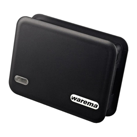
WAREMA MSE Compact 2 REG User manual

2018553_b•en•2018-02-01 We reserve the right to make technical changes 1
Operating and installation instructions
MSE Compact 2/3/4/6 REG
Keep for future use!
Valid from 1 February 2018
General information
The MSE Compact 2/3/4/6 REG motor control unit is an
electronic control device for the non-floating control of
up to 6 sun shading drives. The MSE and drives have a
230VAC power supply.
Connected drives can be operated on-site with a suitable
operating element, and control through a sun shading con-
trol system is also possible. The required control voltage
of 24V DC is generated in the MSEs. Multiple MSEs can
be consolidated to a group and controlled together.
Intended use
The MSE Compact 2/3/4/6 REG motor control unit was
developed to control sun shading systems. The approval
of the manufacturer must be obtained for uses outside of
the purposes listed in these instructions.
Safety instructions
WARNING
The electrical installation must be per-
formed by a certified electrician in ac-
cordance with the electrical installation
regulations published by the Association
of German Electrical Engineers (VDE
0100) or the standards and regulations of
the country in which the device is being
installed. The electrician must observe the
installation instructions included with the
supplied electrical devices.
WARNING
If hazard-free operation cannot be assu-
med, the device may not be started or
must be deactivated. This assumption is
justified if:
the housing or the connecting lines show
signs of damage,
the device is no longer working.
WARNING
It is important to comply with the fol-
lowing points in the interest of personal
safety.
■Make sure that no persons or objects are located in the
path of any driven parts (blinds, roller shutters, etc.)!
■Disconnect the MSE from the operating voltage if
cleaning or other maintenance work must be performed!
Function
Tripping a switch on the subassembly can activate one of
the two integrated control programs for the run time for 2
motors each at the same time. The defined run time always
remains effective in pairs, regardless of any group that may
have been built.
On the encoding switch you can perform the following set-
tings:
Motor Switch position Programme
1-2 S1 ON permanent mode
OFF* time mode
3-4 S2 ON permanent mode
OFF* time mode
5-6 S3 ON permanent mode
OFF* time mode
*= factory setting
ON
S1 S2 S3
Fig. 1 factory setting encoding switch
Program 1:
Local operation with time mode:
This control behaviour is especially useful for slat products,
such as external venetian blinds: The sun shading moves
into the corresponding direction after the button is pressed.
If the button is pressed for more than 2.5 seconds, the
control switches to lock mode. The button may then be
released. The sun shading system moves until the fixed run
time of 3 minutes has expired. To release lock mode and
stop the motor, the button opposite the move command
button must be pressed briefly. If you simply want to tilt the
slats, you can briefly touch one of the buttons.
Program 2:
Local operation in permanent mode:
This control behaviour is useful for roller shutters and fabric
products: the sun shading system moves after the local
button is pressed in the corresponding direction and im-
mediately goes into lock mode. The push button may then
be released and the sun shading system will move until
the fixed run time of 3 minutes has expired. To release lock
mode and stop the motor, the button opposite the move
command button must be pressed briefly.
2018553_b•en•2018-02-01We reserve the right to make technical changes
2
Central operation:
The local operation is blocked for the duration of central
operation; any current move commands will be deleted.
Building groups:
Building groups is possible by looping the push button
lines through several push button inputs. The looped-
through group control line allows the building of groups
across motor control units.
Installation
The motor control unit is designed for distributor installa-
tion (DIN rail-mounted housing).
OTICEN Set the encoding switches according to the
desired function (see page 1).
When installing the device in a distributor, clip it
onto a symmetrical DIN rail (TH 35 according to
EN60715: 2001).
The motor control unit is electrically connected accord-
ing to the wiring diagram on the back (see Fig. 4).
Electrical connection
An on-site overload current protection device (fuse) and a
disconnecting and isolating switch to switch off the entire
system must be provided.
Commissioning
The device is ready for operation after the installation has
been completed and the operating voltage applied.
Maintenance
There are no parts within the device that require mainte-
nance. In the event of a malfunction, the installed miniature
fuse may only be exchanged by a certified electrician.
Liability
Failure to comply with the product information contained in
these instructions and any use of the device other than its
intended use and purpose may result in the manufacturer
refusing to honour warranty claims for product damage. In
this case, liability for consequential damage to persons or
property will also be excluded. Also observe the informa-
tion in the operating instructions for your sun shading
system. The automatic or manual operation of the sun
shading system when iced over as well as using the sun
shading system during severe weather may cause dam-
age and must be prevented by the user through suitable
precautions.
Disposal
After use, the device must be disposed of according to
legal regulations or turned in to your local recycling centre.

3
2018553_b•en•2018-02-01 We reserve the right to make technical changes
Technical data
MSE Compact
2/3/4/6 REG min. typ. max. Unit
Supply 230 V AC
Operating voltage 198 230 253 V AC
Power consumption 0.6 1.1 3.6 W
Output per drive
Switching capacity at
230 V AC/cos ϕ =0.6 500 VA
Inputs (safety extra low voltage)
Voltage, active 8 24 36 V DC
Current, active 0.5 1 1.5 mA
Voltage, inactive –0.5 0 1 V DC
Run time up/down 3 min
Ambient conditions
Operating temperature 0 20 50 °C
Storage temperature 0 20 50 °C
Humidity
(not condensing) 10 40 85 %Hrel
Housing
Dimensions See Fig. 2 and Fig. 3
Miscellaneous
Automatic operation Type 1
Software class A
Degree of protection IP 30
Safety class II
Conformity can be viewed at
www.warema.com
This device complies with the EMC directives for use in re-
sidential and commercial areas.
Connection terminals
Power cable 2.5 mm2
Motor line 2.5 mm²
Push button and con-
trol line 1.0 mm2
Article number
MSE Compact 2 REG 2016481
MSE Compact 3 REG 2016483
MSE Compact 4 REG 2016485
MSE Compact 6 REG 2016487
WAREMA Renkhoff SE
Hans-Wilhelm-Renkhoff-Strasse 2
97828 Marktheidenfeld,
Germany
60 mm
95 mm
90 mm
72 mm
4 MW
60 mm
Fig. 2 DIN rail-mounted housing 4 MW for
MSE Compact 2 / 3 / 4
60 mm
95 mm
90 mm
106 mm / 6 MW
60 mm
Fig. 3 DIN rail-mounted housing 6 MW for MSE Compact 6

2018553_b•en•2018-02-01We reserve the right to make technical changes
4
MSE Kompakt 6
ON
S1 S2 S3
F1: 6,3 AT H
F2: 6,3 AT H
F3: 6,3 AT H
S1
S1
Motor 1
Motor 1
Motor 2
Motor 2
Motor 3
Motor 3
Motor 4
Motor 4
Motor 5
Motor 5
Motor 6
Motor 6
Zentrale
Zentrale
Taster 1
Taster 1
P
P
Taster 2
Taster 2
P
P
Taster 3
Taster 3
P
P
Taster 4
Taster 4
P
P
Taster 5
Taster 5
P
P
Taster 6
Taster 6
P
P
X5:
X5:
X6:
X6:
X2:
X2:
X1:
X1:
PE
N
L
Power line
provided by customer
230 V AC,
50 Hz, 16 A
ATTENTION:
Only one motor may be connected
per motor terminal set.
If interconnected, the motor will
be damaged!
PE
N
L
1 32
BU BK BN GNYE
M∼
Motor 1
1 32
BU BK BN GNYE
M∼
Motor 2
NPE NPE
1 32
BU BK BN GNYE
M∼
Motor 3
1 32
BU BK BN GNYE
M∼
Motor 4
NPE NPE
1 32
BU BK BN GNYE
M∼
Motor 5
1 32
BU BK BN GNYE
M∼
Motor 6
NPE NPE
F
to other MSE
- Max. group size 200 MSE (see
voltage drop diagram).
- Central control line length (see
voltage drop diagram).
- Length of supply line is limited by the
total motor current.
The number of possible drives per
circuit depends on their
current consumption and the
upstream fuse.
- For max. switching capacity of the
MSE refer to "Technical Data".
- Only push buttons may be used.
- All control lines and push button
lines: Max. line length 200 m for
interference-proof routing, use a
twisted paired line.
Legend
4×2×0.8 mm ∅ shielded, single-wire
2×2×0.8 mm ∅ shielded, single-wire
H05RR-F4G 0.75 mm2BK, type WAREMA
3×1.5 mm2
UP
DOWN
Single
push button
(Motor 6)
Connection to:
Floating contacts of the sun shading
control system /
floor distribution control compact
+
DOWN
UP
E
P/C
+
DOWN
UP
+
DOWN
UP
to other MSE
0 V 0 V
Additional wiring variants can be found
in the "Wiring diagrams" document,
art. no. 816345 (from 816345_l)
ATTENTION:
The "0" and "+" connections of the X5
terminal block must be looped through
to every MSE.
Group push button
(Motor 2 and 3)
X1:
X1:
L
L
N
N
L
L
N
N
Motor1
Motor1
Motor2
Motor2
Motor3
Motor3
Motor4
Motor4
Zentrale
Zentrale
X5:
X5:
0V
0V
S1
S1
+
+
Taster1
Taster1
P
P
Taster2
Taster2
P
P
Taster3
Taster3
P
P
Taster4
Taster4
POWER
POWER
MSE Kompakt 4
S1S2
ON
Terminal assignment for
MSE Compact 2,3,4-fold
using the MSE Compact 4 as an example
123456789101112
1615141356789 10 11 121234
Fig. 4 Connection example MSE Compact 6 REG in 6 MW housing
This manual suits for next models
3
Other WAREMA Control Unit manuals

WAREMA
WAREMA WMS WebControl pro User manual

WAREMA
WAREMA MSE Compact 1 UP User manual

WAREMA
WAREMA MSE Haustechnik ZL User manual

WAREMA
WAREMA GA Kompakt User manual

WAREMA
WAREMA Minitronic Dialog User manual

WAREMA
WAREMA Uniswitch ZL User manual

WAREMA
WAREMA GA Kompakt User manual

WAREMA
WAREMA Omnexo User manual

WAREMA
WAREMA WMS WebControl User manual

WAREMA
WAREMA climatronic WebControl User manual