Western UltraMount MVP V-Plow Series User manual

July 1, 2005
Lit. No. 28270, Rev. 00
MECHANIC'S GUIDEMECHANIC'S GUIDE
MECHANIC'S GUIDE
SNOSNO
SNOSNO
SNOWPLWPL
WPLWPL
WPLOO
OO
OWSWS
WSWS
WS
Featuring the
FF
FF
FloStaloSta
loStaloSta
loStatt
tt
t®®
®®
®HyHy
HyHy
Hydrdr
drdr
draulic System &aulic System &
aulic System &aulic System &
aulic System &
IsolaIsola
IsolaIsola
Isolation Module Light Systemtion Module Light System
tion Module Light Systemtion Module Light System
tion Module Light System
SNOSNO
SNOSNO
SNOWPLWPL
WPLWPL
WPLOO
OO
OWSWS
WSWS
WS
CAUTION
Read this manual before servicing the snowplow.


Lit. No. 28270, Rev. 00 July 1, 2005
3
TABLE OF CONTENTS
Introduction .................................................................................................... 4
Preface ...................................................................................................... 4
Required Tools ......................................................................................... 4
Available Service Items ........................................................................... 4
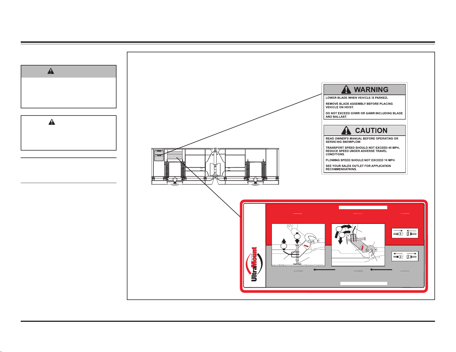
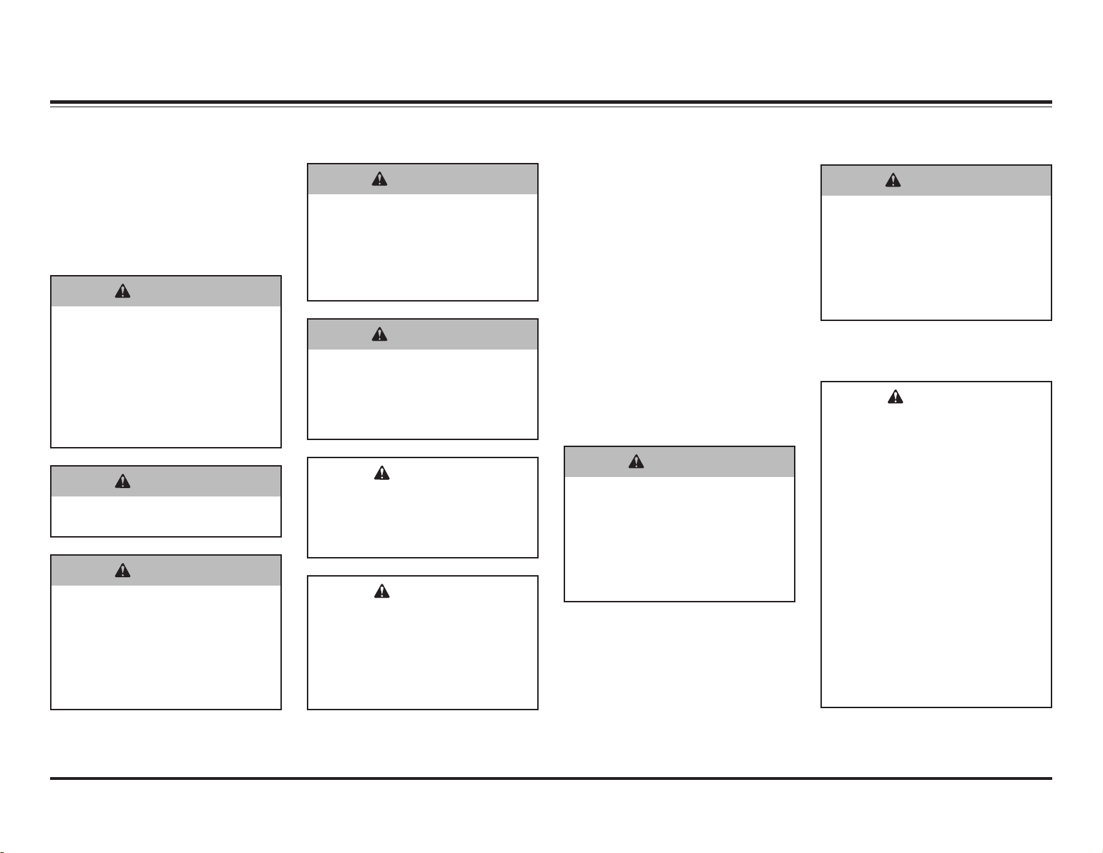
Safety Information .......................................................................................... 5
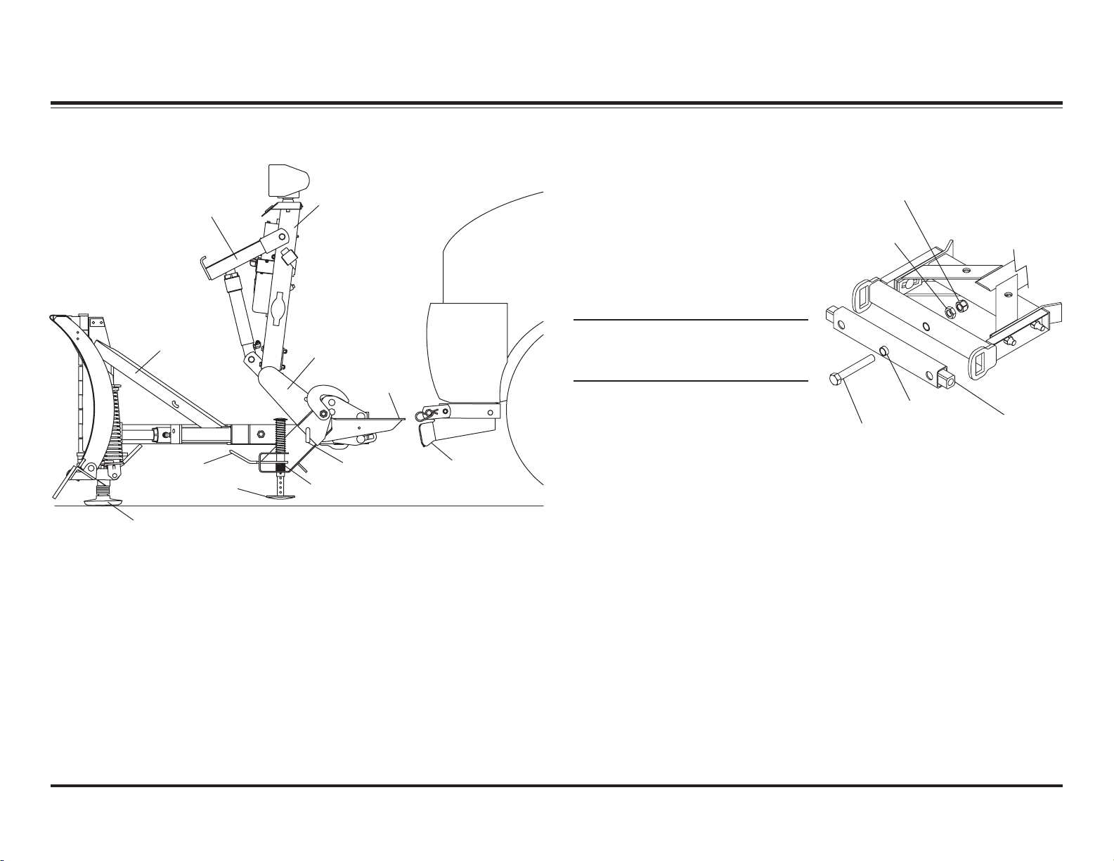
System Overview............................................................................................ 8
Blade, T-Frame & Lift Assemblies .......................................................... 8
Snowplow Components .................................................................... 8
Securing Pivot Bar to T-Frame ......................................................... 8
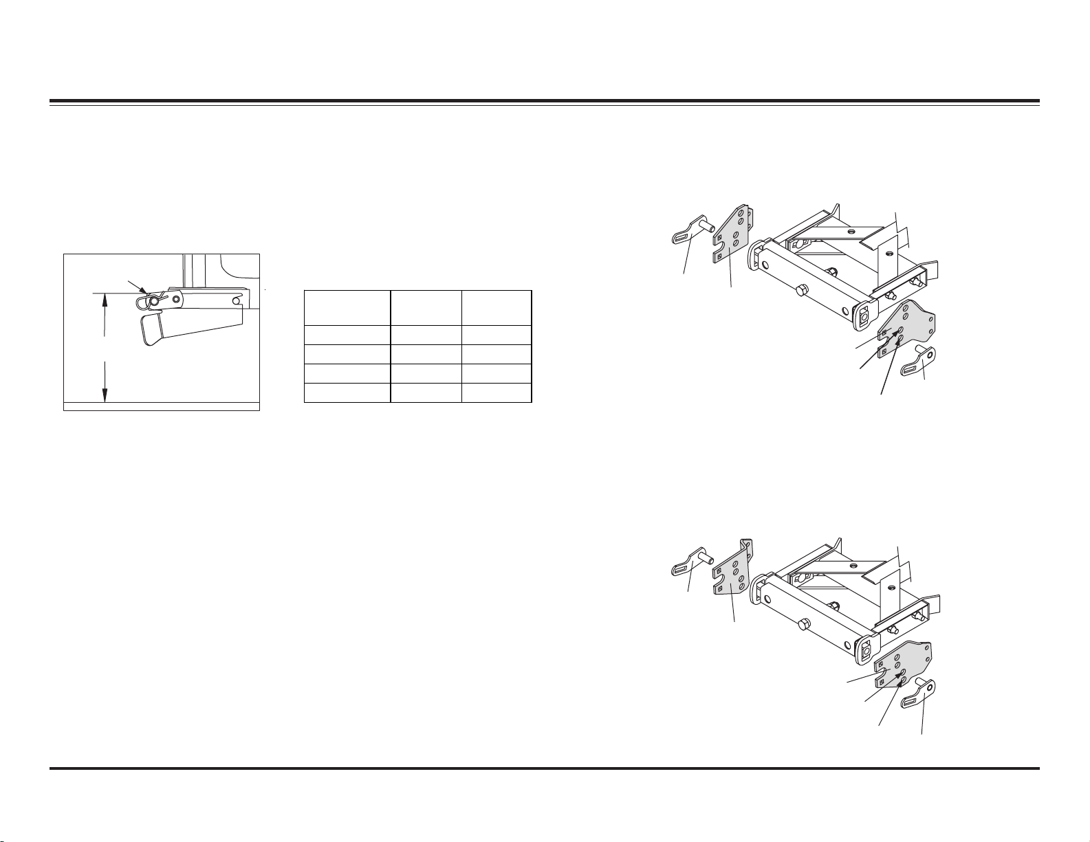
Pivot Plates ........................................................................................ 9
Initial Stand Shoe Setup .................................................................. 10
Stand Shoe Adjustment .................................................................. 10
Stacking Stop Configuration .......................................................... 11
T-Frame Leveling Adjustment ........................................................ 12
Blade Spring Replacement Tool (PN 20043) ................................. 13
Lift Arm & Lift Ram Installation ...................................................... 14
Headlamp Beam Aiming ................................................................. 15
Vehicle Lighting Check ................................................................... 15
Hydraulic ................................................................................................ 16
FloStat®Hydraulic System .............................................................. 16
Specifications .................................................................................. 16
Hydraulic Fitting and Hose Installation ......................................... 17
Hose Routing and Fitting Orientation ............................................ 18
Assembly ......................................................................................... 19
Cartridge Valves .............................................................................. 20
Relief Valves .................................................................................... 21
Pilot-Operated Check Valves .......................................................... 22
Ram Seal Installation ...................................................................... 23
Electrical ................................................................................................. 24
Wiring ............................................................................................... 24
Controls .................................................................................................. 25
General Information ........................................................................ 25
Adapter Cable (PN 66760K) ............................................................ 25
CabCommand Hand-Held Control (9 Button) ................................ 26
Joystick Control .............................................................................. 28
CabCommand Hand-Held Control (6 Button) ................................ 30
Fuse Replacement ........................................................................... 32
Terminal Removal Tool .................................................................... 33
Replacing Terminals ........................................................................ 33
14-Pin Connector Pin Assignments ............................................... 33
Theory of Operation ..................................................................................... 34
Snowplow Headlamps ........................................................................... 34
Snowplow Daytime Running Lights ..................................................... 34
Snowplow Hydraulics ............................................................................ 34
Electrical & Hydraulic Schematics.............................................................. 35
Electrical Schematic .............................................................................. 36
Hydraulic Schematic .............................................................................. 37
Raise ....................................................................................................... 38
Lower ...................................................................................................... 40
Angle Right ............................................................................................. 42
Angle Left ............................................................................................... 44
Vee .......................................................................................................... 46
Scoop ...................................................................................................... 48
Right Retract .......................................................................................... 50
Right Extend ........................................................................................... 52
Left Retract ............................................................................................. 54
Left Extend ............................................................................................. 56
Hold in Raised Position ......................................................................... 58
Striking An Object While Plowing ........................................................ 59
High Beam Headlamps with Snowplow Connected to Vehicle .......... 61
Low Beam Headlamps with Snowplow Connected to Vehicle ........... 62
Troubleshooting Guide ................................................................................ 63

Lit. No. 28270, Rev. 00 July 1, 2005
4
PREFACE
This guide has been prepared to
assist the trained mechanic in the
service of WESTERN®snowplows. It
also provides safety information and
recommendations. We urge all
mechanics to read this manual
carefully before attempting to service
the WESTERN snowplow equipment
covered by this guide.
INTRODUCTION
Service of your WESTERN
snowplow equipment is best
performed by your local Western
Products outlet. They know your
snowplow best and are interested in
your complete satisfaction.
REQUIRED TOOLS
• Long/Slender Needle Nose Pliers
• Flat Screwdriver
• 12V Test Light
• Torque Wrench (in-lb)
• Allen Wrench Set
• Combination Wrenches: 3/8",
7/16" (2), 1/2", 11/16", 3/4", 7/8",
1-1/16", and 1-1/8"
• 1/4" Drive Ratchet, 6" ext., 5/16",
1/4" and 3/8" socket
• 3/8" Drive Ratchet, 1/2" and
9/16" Sockets
• 1/2" Drive Ratchet, Deep
Sockets: 11/16", 7/8", 1-1/16",
1-1/8"
• Digital Volt/Ohmmeter
• Pressure Test Kit
• Flashlight
• Pick Set
• Hammer
• Pencil Magnet
• #20 TORX®Driver
• 10- and 15-amp Automotive
Blade-Type Fuses
TORX®is a registered (®) trademark of Textron, Inc.
AVAILABLE SERVICE ITEMS
• Motor Bearing Sleeve Repair Kit: PN 64589
• Isolation Module Tester: PN 64431
• Pressure Test Kit: PN 56679
• MVP®Electrical Tester: PN 63145
• Electrical Tester Isolation Module Adapter: PN 64427
• Spring Removal Tool: PN 20043
• Test Harness: PN 28957

Lit. No. 28270, Rev. 00 July 1, 2005
5
NOTE: Identifies tips, helpful hints
and maintenance information the
owner/operator should know.
SAFETY INFORMATION
INSTRUCTIONS
Pull and hold Lock Pin out; then rotate Handle DOWN
and release Lock Pin. It must lock into LOWER hole.
Push down top of Shoe; Shoe will be on the
ground. Repeat steps 2 and 3 on other side of plow.
Back vehicle away.
After lowering blade and
turning control off, disconnect
electrical connections.
STEP 3 STEP 2 STEP 1
After seating plow horns in receiver brackets,
pull Handle up; Shoe will lift off the ground.
Pull and hold Lock Pin out; then rotate Handle UP
and release Lock Pin. It must lock into UPPER
hole. Stand Hook must grip Receiver Pin.
Plug in electrical connections.
Repeat steps 1 and 2 on
other side of plow.
STEP 1 STEP 2 STEP 3
ON
OFF OFF
ON
Receiver Pin
Stand Hook
Handle
(Pull)
Lock Pin
Shoe
Handle
MOUNTING PLOW (ON)
Read Owner's Manual for complete instructions.
REMOVING PLOW (OFF)
Read Owner's Manual for complete instructions.
Patents: US 4,999,935; 5,420,480; RE 35,700; 6,145,222; 6,209,231; 6,253,470; 6,526,677; CAN 2,060,425; patents pending.
67796
®
Please become familiar with and inform
users about the warning and instruction
labels on the back of the blade!
Warning and Caution Label
Instruction Label
CAUTION
Indicates a situation that, if not
avoided, could result in
damage to product or property.
WARNING
Indicates a potentially
hazardous situation that, if not
avoided, could result in death
or serious personal injury.
SAFETY DEFINITIONS

Lit. No. 28270, Rev. 00 July 1, 2005
6
SAFETY INFORMATION
SAFETY PRECAUTIONS
Improper installation and operation
could cause personal injury, and/or
equipment and property damage.
Read and understand labels and the
Owner’s Manual before installing,
operating, or making adjustments.
WARNING
Lower blade when vehicle is
parked. Temperature changes
could change hydraulic
pressure, causing the blade to
drop unexpectedly or damaging
hydraulic components. Failure
to do this can result in serious
personal injury.
WARNING
Remove blade assembly before
placing vehicle on hoist.
WARNING
Keep 8' clear of the blade when
it is being raised, lowered or
angled. Do not stand between
the vehicle and blade or
directly in front of the blade. If
the blade hits or drops on you,
you could be seriously injured.
WARNING
Keep hands and feet clear of
the blade and T-frame when
mounting or removing the
snowplow. Moving or falling
assemblies could cause
personal injury.
WARNING
Do not exceed GVWR or GAWR
including blade and ballast. The
rating label is found on the
driver-side vehicle door
cornerpost.
CAUTION
Refer to the current Selection
List for minimum vehicle
recommendations and ballast
requirements.
CAUTION
To prevent accidental
movement of the blade, always
turn the ON/OFF switch to OFF
whenever the snowplow is not
in use. The control indicator
light will turn off.
PERSONAL SAFETY
• Wear only snug-fitting clothing
while working on your vehicle or
snowplow.
• Do not wear jewelry or a necktie,
and secure long hair.
• Wear safety goggles to protect
your eyes from battery acid,
gasoline, dirt and dust.
• Avoid touching hot surfaces such
as the engine, radiator, hoses
and exhaust pipes.
• Always have a fire extinguisher
rated BC handy, for flammable
liquids and electrical fires.
FIRE AND EXPLOSION
Be careful when using gasoline. Do
not use gasoline to clean parts. Store
only in approved containers away
from sources of heat or flame.
WARNING
Gasoline is highly flammable
and gasoline vapor is explosive.
Never smoke while working on
vehicle. Keep all open flames
away from gasoline tank and
lines. Wipe up any spilled
gasoline immediately.
VENTILATION
BATTERY SAFETY
WARNING
Vehicle exhaust contains deadly
carbon monoxide (CO) gas.
Breathing this gas, even in low
concentrations, could cause
death. Never operate a vehicle
in an enclosed area without
venting exhaust to the outside.
CAUTION
Batteries normally produce
explosive gases which can
cause personal injury.
Therefore, do not allow flames,
sparks or lit tobacco to come
near the battery. When
charging or working near a
battery, always cover your face
and protect your eyes, and
also provide ventilation.
Batteries contain sulfuric acid
which burns skin, eyes and
clothing.
Disconnect the battery before
removing or replacing any
electrical components.

Lit. No. 28270, Rev. 00 July 1, 2005
7
SAFETY INFORMATION
HYDRAULIC SAFETY
• Always inspect hydraulic
components and hoses before
using. Replace any damaged or
worn parts immediately.
• If you suspect a hose leak, DO
NOT use your hand to locate it.
Use a piece of cardboard or
wood.
WARNING
Hydraulic fluid under pressure
can cause skin injection injury.
If you are injured by hydraulic
fluid, get medical attention
immediately.
TORQUE CHART
CAUTION
Read instructions before
assembling. Fasteners should
be finger tight until instructed
to tighten according to torque
chart. Use standard methods
and practices when attaching
snowplow including proper
personal protective safety
equipment.
Recommended Fastener Torque
Chart (Ft.-Lb.)
Size SAE
Grade 2
SAE
Grade 5
SAE
Grade 8
1/4-20
5/16-18
3/8-16
3/8-24
7/16-14
1/2-13
9/16-12
5/8-11
3/4-10
7/8-9
1-8
6
11
19
24
30
45
66
93
150
150
220
9
18
31
46
50
75
110
150
250
378
583
13
28
46
68
75
115
165
225
370
591
893
Metric Grade 8.8 (Ft.-Lb.)
Size TorqueSize
Torque
M 6
M 8
M 10
M 12
M 14
M 16
7
17
35
60
95
155
These torque values apply to fasteners
except those noted in the instruction.

Lit. No. 28270, Rev. 00 July 1, 2005
8
SYSTEM OVERVIEW – BLADE, T-FRAME & LIFT ASSEMBLIES
SNOWPLOW COMPONENTS
Plow Horn
Lift Arm
Upper
Lift Frame
T-Frame
Assembly Lower
Lift Frame
Receiver
Bracket
Lock Pin
Shoe
Handle
Blade Shoe
Stand
SECURING PIVOT BAR TO
T-FRAME
1. Install a 1" jam nut and tighten to
25 ft-lb, then loosen 1/16 turn.
2. Hold 1" cap screw and jam nut to
prevent rotation, and install 1"
locknut. Tighten locknut securely
against jam nut.
NOTE: When properly adjusted,
pivot bar should pivot freely
without any looseness.
1" Locknut
1" Jam Nut
Pivot Ba
r
Pivot
Bushing
1" x 7"
Cap Screw

Lit. No. 28270, Rev. 00 July 1, 2005
9
Configuration 3
Configuration 4
Pivot Plate B
(Flat Side Up)
Pivot
Pin
Pivot
Pin Pivot Plate A
(Flat Side Up)
PIVOT PLATES
1. Measure the distance "d" from
the ground to the top edge of the
receiver bracket. Measure both
sides and determine average
value "d".
d
Top Edge of
Receiver
Pivot Plate A
(Bevel Side Up)
Configuration 1
Configuration 2
Pivot
Pin
Pivot
Pin Pivot Plate B
(Bevel Side Up)
Dimension
"d" Config. Stacking
Stop
13.0"–14.5" 1 No
14.5"–16.0" 2 Yes
16.0"–17.5" 3 Yes
17.5"–19.0" 4 Yes
Pivot Plate Mounting and Hole
Positions for Configurations 1 & 2
Pivot Plate Mounting and Hole
Positions for Configurations 3 & 4
2. Use dimension "d" from Step 1,
and the following chart to
determine the proper pivot plate
mounting position and pivot hole
selection.
Pivot Plate Configuration Chart
SYSTEM OVERVIEW – BLADE, T-FRAME & LIFT ASSEMBLIES

Lit. No. 28270, Rev. 00 July 1, 2005
10
SYSTEM OVERVIEW – BLADE, T-FRAME & LIFT ASSEMBLIES
Config. 1
Config. 2
Config. 3
Config. 4
INITIAL STAND SHOE SETUP
The illustration below shows the
recommended starting positions for
configuring your stand shoes.
9-3/4" to 11-1/4"
1-3/8" to 2-1/8"
Roll Pin
STAND SHOE ADJUSTMENT
1. Attach plow to the vehicle mount.
With plow lowered to the ground
and on level pavement, measure
the dimension from the ground to
the center of the pivot bar cap
screw. This dimension must be
9-3/4" to 11-1/4".
2. With the plow attached and on
the ground, place the stand arm
in the lower position with the lock
pin engaged and with the stand
shoe fully retracted in the "up"
position. Measure the distance
from the ground to the bottom of
the stand shoe. This distance
should be 1-3/8" to 2-1/8". The
stand can be adjusted to achieve
this dimension by removing the
roll pin and selecting the proper
hole in the stand stem. When the
stand height is correct, cut and
remove the spring tie.

Lit. No. 28270, Rev. 00 July 1, 2005
11
Stacking
Stops
Cap
Screws
Locknuts
Cross
Tube
Mounting
Bracket
NOTE: Stacking stops are used
only with configurations 2, 3 and 4.
Stacking stops are not used for
configuration 1.
STACKING STOP
CONFIGURATION
SYSTEM OVERVIEW – BLADE, T-FRAME & LIFT ASSEMBLIES
Configuration 2
Driver-Side
Stacking Stops
Orientation - Long
End Rearward
Configuration 3
Driver-Side
Stacking Stops
Orientation - Long
End Upward
Configuration 4
Driver-Side
Stacking Stops
Rear T-frame
Channel
Orientation - Long
End Downward

Lit. No. 28270, Rev. 00 July 1, 2005
12
T-FRAME LEVELING
ADJUSTMENT
After the plow has been installed on
the vehicle in the correct
configuration, a fine adjustment can
be made to bring the cutting edges of
the plow in full contact with the
ground across the entire cutting
edge. This adjustment feature should
be used as the cutting edges begin
to wear in order to maintain an even
wear pattern across both cutting
edges and provide good scraping
action.
1. Plow must be installed on a
properly ballasted vehicle, in the
correct configuration.
2. Vehicle and plow must be on a
level surface.
3. Temporarily remove the blade
shoes during this adjustment
procedure.
4. Place blade wings in scoop
position on the ground with no
tension on lift chains.
Locking
Plate
Pivot Bolt
and Nut
Locking Bolt and Nut
(Torque to 250 ft-lb)
5. Loosen the locking bolts and the
pivot bolts on the T-frame just
enough to allow the lock plates to
move back and forth freely. (See
figure below.)
It may be necessary to pry one
or both locking plates loose in
order to relieve any tension in the
T-frame and allow the blade to
find a level position.
6. Raise and lower the blade
several times. The cutting edge
should be contacting the level
surface across the full length of
the cutting edge.
7. Move the locking plates rearward
by hand as far as they will go
and tighten the locking bolts and
the pivot bolts to 250 ft-lb.
8. Verify that the cutting edges
remain in full contact with the
ground while the wings are
shifted from the scoop position to
a Vee position.
9. Reinstall blade shoes.
SYSTEM OVERVIEW – BLADE, T-FRAME & LIFT ASSEMBLIES

Lit. No. 28270, Rev. 00 July 1, 2005
13
BLADE SPRING
REPLACEMENT TOOL
(PN 20043)
1. Insert the threaded rod in
through the hole in the channel
weldment. Be sure the threaded
hole in the tab on the rod is
nearest to the channel.
CAUTION
Servicing the trip springs
without special tools and
knowledge could result in
personal injury.
2. Place the assembly on to the top
anchor above the spring as
illustrated. Be sure to place the
spring bar in between the tabs on
the rod. Insert the 1/2" x 1-1/2"
Gr. 5 cap screw through the
outside tab, through the hole in
the spring bar, and tighten into
the threaded hole.
3. Drop the 1/2" flat washer Gr. 8
over the threaded rod and fasten
the nut to the threaded rod.
Tighten the nut until the spring
bar is raised enough to insert the
pin through the pin hole. Center
the pin within the hole.
4. Loosen the nut to lower the
spring bar. Remove the spring
tool assembly by removing the
1/2" cap screw.
5. Remove the spring from the
blade by removing the bolt from
the bottom of the spring bar.
6. Insert the new spring with the
spring bar up through the top
anchor on the blade. Fasten the
bottom of the spring bar to the
anchor on the trip edge with the
previously removed fasteners.
Tighten.
7. Repeat Steps 1 and 2 above.
8. Repeat Step 3 above, except
remove the pin from the spring bar.
9. Repeat Step 4 above.
Channel
Rod
1/2 x 1-1/2"
Cap Screw Gr. 5 1/2" Coupling
Nut
1/2" Flat Washer Gr. 8
1/4 x 1-1/4"
Pin
SYSTEM OVERVIEW – BLADE, T-FRAME & LIFT ASSEMBLIES

Lit. No. 28270, Rev. 00 July 1, 2005
14
LIFT ARM & LIFT RAM INSTALLATION
Lift Arm
3/4" Flat
Washer
Cotter Pin
Lift
Arm
Lift Frame
Vertical
Support
3/4" Plastic
Washer
3/4" x 3-1/4"
Clevis Pin
3/4" x 3-1/4" Clevis Pin
3/4" x 3"
Heat Treated (HT) Pin
3/4"
Washer
Lift Ram
Cotter Pin
Cotter Pin
3/4"
Washer
SYSTEM OVERVIEW – BLADE, T-FRAME & LIFT ASSEMBLIES

Lit. No. 28270, Rev. 00 July 1, 2005
15
VEHICLE LIGHTING CHECK
Check the operation of vehicle and
plow lights with plow mounted to
vehicle and all harnesses connected.
• Turn Signals and Parking Lamps
• Headlamps
• Daytime Running Lamps (DRLs)
• Joystick Control or
CabCommand Control
The control indicator light should
light whenever the control
ON/OFF switch and the ignition
(key) switches are both in the
ON Position. The snowplow
electrical plugs must be
connected to the vehicle
electrical plugs.
SYSTEM OVERVIEW – BLADE, T-FRAME & LIFT ASSEMBLIES
HEADLAMP BEAM AIMING
Torque headlamp fasteners to 45 ft-lb
once correct visual aim is achieved.
1. Place vehicle on a level surface
25 feet in front of a matte-white
screen, such as a garage door.
The screen should be
perpendicular both to the ground
and to the vehicle centerline.
2. The vehicle should be equipped
for normal operation. The
snowplow blade should be in
place and in raised position. Below
are steps listed by the Society of
Automotive Engineers (SAE)
pertinent to headlamp aiming in
specification #SAE J599d.
3. Prepare vehicle for headlamp
aim or inspection. Before
checking beam aim, the
inspector will:
a. Remove ice or mud from
under fenders.
b. Set tire inflation pressures to
the values specified on
vehicle information label.
c. Check springs for sag or
broken leaves.
d. See that there is no load in
the vehicle other than the
driver and ballast as specified
in the Selection List.
e. Check functioning of any
automatic vehicle leveling
systems and specific
manufacturer’s instructions
pertaining to vehicle
preparation for headlamp
aiming.
f. Clean lenses.
g. Check for bulb burnout and
proper beam switching.
h. Stabilize suspension by
rocking vehicle sideways.
4. Mark (or tape) the vertical
centerline of the snowplow
headlamps and the vertical
Vertical
Centerline
ahead of DS
Snowplow
Headlamp
Align with
vehicle
centerline.
Vertical
Centerline
ahead of PS
Snowplow
Headlamp
Screen
Located
25 Feet from
Snowplow
Headlamps
Horizontal
Centerline
of Snowplow
Headlamps
High Intensity Zones
of Snowplow Headlamps
on Low Beam
centerline of the vehicle on the
screen. Mark the horizontal
centerline of the snowplow
headlamps on the screen
(distance from ground to snow-
plow headlamp centers).
5. Align the top edge of the high
intensity zone of the snowplow
lower beam below the horizontal
centerline and the left edge of
the high intensity zone on the
vertical centerline for each
snowplow headlamp. (Refer to
diagram below.)

Lit. No. 28270, Rev. 00 July 1, 2005
16
FloStat®HYDRAULIC SYSTEM
Western Products’ FloStat hydraulic
system provides a fast and uniform
speed of lifting and angling. The
system raises the blade in two
seconds, and all angling functions
are less than five seconds. For
hydraulic fluid type and filling
instructions, see Hydraulic System in
the Maintenance section of the
Owner’s Manual.
Drain Plug
Fill Plug
12V DC with +/– connection
1700–1800 psi pump relief valve
3950–4050 psi angling relief valve
4.5" dia. 1.04 kw motor
Hydraulic Hose SAE 100R1
Quill
SYSTEM OVERVIEW – HYDRAULIC
SPECIFICATIONS
Relief Valve Settings
• Pump relief valve = 1750 psi.
2-1/2–2-3/4 turns CCW from fully
seated
• Primary relief valve = 3500 psi.
1-1/2–1-3/4 turns CCW from fully
seated
• Secondary relief valve = 4000 psi.
1-1/4–1-1/2 turns CCW from fully
seated
Fluid Capacity (Hydraulic Fluid)
• Unit Reservoir = 1-3/4 Quarts
• System Total = 2-1/2 Quarts
CAUTION
Do not mix different types of
hydraulic fluid. Some fluids are
not compatible and may cause
performance problems and
product damage.
Electrical System (Approximate)
• Solenoid Coil Resistance =
7 Ohms at room temperature
• Solenoid Coil amp. Draw =
1.5 amp
• Motor Relay Coil Resistance =
16–17 Ohm
• Motor Relay Amp. Draw = 0.7 amp
• Maximum Motor Amp. Draw =
190 amp at 1750 psi.
• Switch Accessory Lead Draw =
0.75 amp
Vehicle Control Harness Fuses
• Park/Turn = 15 amp (Automotive
Blade-Type Fuses)
• Control = 10 amp (Automotive
Blade-Type Fuses)
Fastener Torque
• Pump Bolts = 150–160 in-lb
• Motor Bolts = 30–40 in-lb
• Reservoir Bolts = 15–20 in-lb
• Cartridges = 120–144 in-lb
• Check Valves = 120–144 in-lb
• Coil Nuts = 48–60 in-lb
• Secondary Manifold Block
Assembly Bolts = 105–115 in-lb
•Angle Ram
Piston Locknuts = 100–120 ft-lb
Gland Nuts = 150–180 ft-lb
Hydraulic Fluid
Use WESTERN®High Performance
Fluid to -40°F (-40°C) or other fluid
conforming to military specification
MIL-H-5606A, such as Mobil Aero
HFA or Shell AeroShell®Fluid 4. Use
of other than these recommended
fluids may cause poor hydraulic
system performance and damage to
internal components.
Solenoid Valve Spool
• Approx. Solenoid Valve Spool
Travel = 0.07" for 3- and 4-way
valves. Spool travel for 2-way
valves not detectable with voltage
applied to coil.
Pump Motor
AeroShell®is a registered (®) trademark of Shell Oil Company.

Lit. No. 28270, Rev. 00 July 1, 2005
17
Use the following procedure to
install hydraulic hoses.
1. Screw flare nut onto fitting flare
and hand tighten.
2. Align hose so there are no twists
or sharp bends.
3. Using two wrenches, hold the
hose in position and tighten flare
nut 1/8 to 1/4 turn beyond hand
tight. Final torque on the flare nut
should be approximately 20 ft-lb.
SYSTEM OVERVIEW – HYDRAULIC
HYDRAULIC FITTING AND
HOSE INSTALLATION
NOTE: Overtightening JIC hose
fitting ends will result in a
fractured fitting.
Do not use any type of sealant or
tape on the fittings or hoses. This
could damage product. Always use
two wrenches to ensure proper
tightening of fittings and hoses.
Use the following procedure to
install SAE O-ring fittings in valve
block and rams.
1. Turn jam nut on fitting as far back
as possible.
2. Lubricate O-ring with clean
hydraulic fluid.
3. Screw fitting into port by hand
until the washer contacts port
face and shoulder of the jam nut
threads.
4. Unscrew fitting to proper position
no more than one full turn.
5. Using two wrenches, hold fitting
body in position and tighten jam
nut until the washer again
contacts port face, then tighten
an additional 1/8 to 1/4 turn to
lock fitting in place. Final torque
on the jam nut should be
approximately 20 ft-lb.

Lit. No. 28270, Rev. 00 July 1, 2005
18
HOSE ROUTING & FITTING ORIENTATION
90° O-Ring
Fittings 90° O-Ring
Fittings
90° O-Ring
Fittings
Hose
Wrap
SYSTEM OVERVIEW – HYDRAULIC
Lift Ram Hose
Driver-Side
Base End Hose
Driver-Side
Rod End Hose
3/8 NPTF
Street Elbow
3/8 NPTF
Breather
Long Elbows
Passenger-Side
Base End Hose
Passenger-Side
Rod End Hose

Lit. No. 28270, Rev. 00 July 1, 2005
19
Pump Relief Valve
Motor
Quill
Secondary
Valve Block
Pilot-Operated Check Valve
Primary Valve Block
Solenoid Valve Cartridge
Solenoid Valve Coil
Pump Filter
Reservoir
Standoff
Screw
Magnet
Pump
Pump
Shaft
Seal
Return Screen
Assembly
Retainer Clip
Pickup Tube
Breather
and Elbow
Angle Ram Relief Valves
ASSEMBLY
SYSTEM OVERVIEW – HYDRAULIC

Lit. No. 28270, Rev. 00 July 1, 2005
20
CARTRIDGE VALVES
The MVP®snowplow FloStat®
hydraulic system performs 10 blade
movement functions.
All functions require the vehicle
ignition (key) switch to be in the run
or accessory position and the power
to be activated on the snowplow cab
control.
Nine of the ten hydraulic functions
require energizing the electric motor,
shifting of solenoid cartridge spools
or activating P/O check valves. The
tenth function, lower, does not
energize the motor but requires
shifting of solenoid cartridges.
Solenoid Cartridge
Valve – S1
White/Yellow Wire
(SV08-2004)
Solenoid Cartridge
Valve – S3
Lt. Green Wire
(SV08-43)
Solenoid Cartridge
Valve – S2
Lt. Blue Wire
(SV08-40)
Solenoid Cartridge
Valve – S6
Lt. Blue/Orange Wire
(SV08-30)
Solenoid Cartridge
Valve – S4
Black/White Wire
(SV08-30)
Solenoid Cartridge
Valve – S5
Blue/Orange Wire
(SV08-40)
SV08-43 S3 ON ONON ON
SV08-2004 S1 ON
MOVEMENT
BLADE RAISE LOWER SCOOP
VEE
SV08-30 S6 ON ON
RIGHT
EXTEND
RIGHT
RETRACT
LEFT
RETRACT EXTEND
LEFT
S4SV08-30 ON ON
SV08-40 S2 ON ON ONON
SV08-40 S5 ON ON
MOTOR M ONONON ON ON ON ONON ON
ANGLE
RIGHT
ANGLE
LEFT
SYSTEM OVERVIEW – HYDRAULIC
Table of contents
Other Western Snow Blower manuals

Western
Western UltraMount 2 User manual

Western
Western UltraMount MIDWEIGHT User manual

Western
Western DEFENDER Compact Plow User manual

Western
Western UniMount MVP User manual

Western
Western UltraMount User manual

Western
Western 27550 User manual

Western
Western SHS B Series User manual

Western
Western MVP PLUS Series User manual

Western
Western LSX Series User manual

Western
Western IMPACT UTV Straight Blade Snowplow User manual