logo
Brands
  1. Home
  2. •
  3. Brands
  4. •
  5. MTD
  6. •
  7. Snow Blower
  8. •
  9. MTD Bolens 500 Series User manual

MTD Bolens 500 Series User manual

This manual suits for next models

1

Other MTD Snow Blower manuals

MTD 311-500A User manual

MTD

MTD 311-500A User manual

MTD 190-624 User manual

MTD

MTD 190-624 User manual

MTD 311-300 User manual

MTD

MTD 311-300 User manual

MTD 31AM62EE000 User manual

MTD

MTD 31AM62EE000 User manual

MTD 190-768 User manual

MTD

MTD 190-768 User manual

MTD OEM-190-032 User manual

MTD

MTD OEM-190-032 User manual

MTD Series 200 User manual

MTD

MTD Series 200 User manual

MTD 3BA User manual

MTD

MTD 3BA User manual

MTD 737-0168 User manual

MTD

MTD 737-0168 User manual

MTD 500 Series User manual

MTD

MTD 500 Series User manual

MTD 2P5 User manual

MTD

MTD 2P5 User manual

MTD 2B5 User manual

MTD

MTD 2B5 User manual

MTD C Style User manual

MTD

MTD C Style User manual

MTD 600 Series User manual

MTD

MTD 600 Series User manual

MTD 600 Series User manual

MTD

MTD 600 Series User manual

MTD OEM-190-627 User manual

MTD

MTD OEM-190-627 User manual

MTD Styles C User manual

MTD

MTD Styles C User manual

MTD YARD-MAN 31AE5KLG801 User manual

MTD

MTD YARD-MAN 31AE5KLG801 User manual

MTD 190-032-101 User manual

MTD

MTD 190-032-101 User manual

MTD OGST-1505E User manual

MTD

MTD OGST-1505E User manual

MTD 310-200 User manual

MTD

MTD 310-200 User manual

MTD 31AH6ZFH729 User manual

MTD

MTD 31AH6ZFH729 User manual

MTD 380 User manual

MTD

MTD 380 User manual

MTD Cub Cadet 221 HP User manual

MTD

MTD Cub Cadet 221 HP User manual

Popular Snow Blower manuals by other brands

Murray 624504X4A Instruction book

Murray

Murray 624504X4A Instruction book

Blizzard POWER PLOW 8100PP owner's manual

Blizzard

Blizzard POWER PLOW 8100PP owner's manual

Craftsman 486.24837 Operator's manual

Craftsman

Craftsman 486.24837 Operator's manual

Yard-Man E2B5 Operator's manual

Yard-Man

Yard-Man E2B5 Operator's manual

ST ST 526 A Operator's manual

ST

ST ST 526 A Operator's manual

Toro Power TRX 1428 OHXE Operator's manual

Toro

Toro Power TRX 1428 OHXE Operator's manual

Ryobi RYAC800 Operator's manual

Ryobi

Ryobi RYAC800 Operator's manual

Poulan Pro 416829 owner's manual

Poulan Pro

Poulan Pro 416829 owner's manual

Poulan Pro 437986 owner's manual

Poulan Pro

Poulan Pro 437986 owner's manual

Brute 1695565 Operator's manual

Brute

Brute 1695565 Operator's manual

Egholm City Ranger 2250 Operator's manual

Egholm

Egholm City Ranger 2250 Operator's manual

Poulan Pro 420915 owner's manual

Poulan Pro

Poulan Pro 420915 owner's manual

GreenWorks SNF402 Operator's manual

GreenWorks

GreenWorks SNF402 Operator's manual

LOFTNESS 601D1 Operator's manual

LOFTNESS

LOFTNESS 601D1 Operator's manual

LOFTNESS 1082I Operator's manual

LOFTNESS

LOFTNESS 1082I Operator's manual

LOFTNESS 481EL Operator's manual

LOFTNESS

LOFTNESS 481EL Operator's manual

White Outdoor 769-01923A Operator's manual

White Outdoor

White Outdoor 769-01923A Operator's manual

Simplicity 1690034 Operator's manual

Simplicity

Simplicity 1690034 Operator's manual

https://manuals.online logo
https://manuals.online logoBrands
  • About & Mission
  • Contact us
  • Privacy Policy
  • Terms and Conditions

Copyright 2026 Manuals.Online. All Rights Reserved.

Printed in U.S.A.
FORM NO
.
772C0720
(7/2004)
IMPORTANT: Read safety rules and instructions
P. O. BOX 1386, KITCHENER, ONTARIO N2G 4J1
carefully before operating equipment.
500 series
Snowthrower
Model 6ML Shown
Operator’s Manual
2
TABLE OF CONTENTS
FINDING MODEL NUMBER
This Operator’s Manual is an important part of your new snow thrower. It will help you to assemble, prepare and
maintain the unitfor best performance. Please read and understand what it says.
Before you start assembling your new snow thrower, please locate the model plate on the
equipment and copy the information from it in the space provided below.The information on the
model plate is very important if you need help from an authorized dealer.
•You can locate the model number by standing behind the unit in the operating position and looking
down at the dash panel. A sample model plate is explained below. For future reference, please copy the
model number and the serial number of the equipment in the space below.
ENGINE INFORMATION
The engine manufacturer is responsible for all engine-related issues with regards to performance, power-rating,
specifications, warranty and service. Please refer to the engine manufacturer’s Owner’s/Operator’s Manual packed
separately with your unit for more information.
CALLING CUSTOMER SUPPORT
If you have difficulty assembling this product orhave any questions regarding the controls, operation or
maintenance of this unit,please call an authorized dealer.
Please have your unit’s model number and serial number ready when you call. See previous section to
locate this information.
Content Page
Customer Support 2
Important Safe Operation Practices 3
Setting Up Your SnowThrower 5
Operating Your Snow Thrower 8
Maintaining Your Snow Thrower 12
Service & Ajustments 13
Off Season Storage 17
Trouble Shooting 18
Warranty 19
Illustrated Parts List 20
Content Page
Copy the model number here:
Copy the serial number here:
MTD PRODUCTS LIMITED
KITCHENER, ON N2G 4J1
1-800-668-1238
XXXXXXXXXX XXXXXXXXXXX
Model Number
Numéro de modèle Serial Number
Numéro de série
www.mtdcanada.com
3
SECTION 1: IMPORTANT SAFE OPERATION PRACTICES
WARNING: This symbol points out important safety instructions which, if not followed, could endanger the
personal safety and/or property of yourself and others. Read and follow all instructions in this manual before
attempting to operate this machine. Failure to comply with these instructions may result in personal injury. When you
see this symbol—heed its warning.
WARNING: Engine Exhaust, some of its constituents, and certain vehicle components contain or emit chemicals
known to State of California to cause cancer and birth defects or other reproductive harm.
DANGER: This machine was built to be operated according to the rules for safe operation in this manual. As with
any type of power equipment, carelessness or error on the part of the operator can result in serious injury. This
machine is capable of amputating hands and feet and throwing objects. Failure to observe the following safety
instructions could result in serious injury or death.
Training
1. Read, understand, and follow all instructions on the
machine and in the manual(s) before attempting to
assemble and operate. Keep this manual in a safe place
for future and regular reference and for ordering
replacement parts.
2. Be familiar with all controls and their proper operation.
Know how to stop the machine and disengage them
quickly.
3. Never allow children under 14 years old to operate this
machine. Children 14 years old and over should read and
understand the operation instructions and safety rules in
this manual and should be trained and supervised by a
parent.
4. Never allow adults to operate this machine without
proper instruction.
5. Thrown objects can cause serious personal injury. Plan
your snow throwing pattern to avoid discharge of material
toward roads, bystanders and the like.
6. Keep bystanders, helpers, pets and children at least 75
feet from the machine while it is in operation. Stop
machine if anyone enters the area.
7. Exercise caution to avoid slipping or falling, especially
when operating in reverse.
Preparation
1. Thoroughly inspect the area where the equipment is to
be used. Remove all door mats, newspapers, sleds,
boards, wires and other foreign objects which could be
tripped over or thrown by the auger/impeller.
2. Always wear safety glasses or eye shields during
operationandwhile performing anadjustment orrepair to
protect your eyes. Thrown objects which ricochet can
cause serious injury to the eyes.
3. Do not operate without wearing adequate winter outer
garments. Do not wear jewelry, long scarves or other
loose clothing which could become entangled in moving
parts. Wear footwear which will improve footing on
slippery surfaces.
4. Use a grounded extension cord and receptacle for all
units with electric start engines.
5. Adjust collector housing height to clear gravel or crushed
rock surfaces.
6. Disengage the control handle before starting the engine.
7. Never attempt to make any adjustments while engine is
running, except where specifically recommended in the
operator’s manual.
8. Let engine and machine adjust to outdoor temperature
before starting to clear snow.
9. Toavoid personalinjury or property damage useextreme
care in handling gasoline. Gasoline is extremely
flammable and the vapors are explosive. Serious
personal injury can occur when gasoline is spilled on
yourself or your clothes which can ignite. Wash your skin
and change clothes immediately.
a. Use only an approved gasoline container.
b. Extinguish all cigarettes, cigars, pipes and other
sources of ignition.
c. Never fuel machine indoors.
d. Never remove gas cap or add fuel while the
engine is hot or running.
e. Allow engine to cool at least two minutes before
refueling.
f. Never over fill fuel tank. Fill tank to no more than
½inch belowbottom of fillerneck toprovide space
for fuel expansion.
g. Replace gasoline cap and tighten securely.
h. If gasoline is spilled, wipe it off the engine and
equipment. Move machine to another area. Wait 5
minutes before starting the engine.
i. Never store the machine or fuel container inside
where there is an open flame, spark or pilot light
(e.g. furnace, water heater, space heater, clothes
dryer etc.).
j. Allow machine to cool at least 5 minutes before
storing.
Operation
1. Do not put hands or feet near rotating parts, in the auger
housing or discharge chute. Contact with the rotating
parts can amputate hands and feet.
2. The auger control handle is a safety device. Never
bypass its operation. Doing so, makes the machine
unsafe and may cause personal injury.
3. The control handle must operate easily in both directions
and automatically return to the disengaged position when
released.
4. Never operate with a missing or damaged discharge
chute. Keep all safety devices in place and working.
5. Never run an engine indoors or in a poorly ventilated
area. Engine exhaust contains carbon monoxide, an
4
odorless and deadly gas.
6. Do not operate machine while under the influence of
alcohol or drugs.
7. Muffler and engine become hot and can cause a burn. Do
not touch.
8. Exercise extreme caution when operating on or crossing
gravel surfaces. Stay alert for hidden hazards or traffic.
9. Exercise caution when changing direction and while
operating on slopes.
10. Plan your snow throwing pattern to avoid discharge
towards windows, walls, cars etc. To avoid property
damage or personal injury caused by a ricochet.
11. Never direct discharge at children, bystanders and pets
or allow anyone in front of the machine.
12. Do not overload machine capacity by attempting to clear
snow at too fast of a rate.
13. Never operate this machine without good visibility or
light. Always be sure of your footing and keep a firm hold
on the handles. Walk, never run.
14. Disengage power to the auger/impeller when
transporting or not in use.
15. Never operate machine at high transport speeds on
slippery surfaces. Look down and behind and use care
when in reverse.
16. If the machine should start to vibrate abnormally, stop the
engine, disconnect the spark plug and ground it against
the engine. Inspect thoroughly for damage. Repair any
damage before starting and operating.
17. Disengage the controlhandle andstopenginebeforeyou
leave the operating position (behind the handles). Wait
until the auger comes to a complete stop before
unclogging the discharge chute, making any
adjustments, or inspections.
18. Never put your hand in the discharge or collector
openings. Always use a clearing tool to unclog the
discharge opening.
19. Use only attachments and accessories approved by the
manufacturer.
20. If situations occur which are not covered in this manual,
use care and good judgment. Call customer assistance
for the name of your nearest servicing dealer.
Maintenance And Storage
1. Never tamper with safety devices. Check their proper
operation regularly.
2. Disengage the control handle and stop engine. Wait until
the auger/impeller come to a complete stop. Disconnect
the spark plug wire and ground against the engine to
prevent unintended starting before cleaning, repairing, or
inspecting.
3. Check bolts, and screws for proper tightness at frequent
intervals to keep the machine in safe working condition.
Also, visually inspect machine for any damage.
4. Do not change the engine governor setting or over-speed
the engine. The governor controls the maximum safe
operating speed of the engine.
5. Snow thrower shave plates and skid shoes are subject to
wear and damage. For your safety protection, frequently
check all components and replace with original
equipment manufacturer’s (O.E.M.) parts only. “Use of
parts which do not meet the original equipment
specifications may lead to improper performance and
compromise safety!”
6. Check controls periodically to verify they engage and
disengage properly and adjust, if necessary. Refer to the
adjustment section in this operator’s manual for
instructions.
7. Maintain or replace safety and instruction labels, as
necessary.
8. Observe proper disposal laws and regulations for gas,
oil, etc. to protect the environment.
9. Prior to storing, run machine a few minutes to clear snow
from machine and prevent freeze up of auger/impeller.
10. Never store the machine or fuel container inside where
there is an open flame, spark or pilot light such as a water
heater, furnace, clothes dryer etc.
11. Always refer to the operator’s manual for proper
instructions on off-season storage.
Your Responsibility:
• Restrict the use of this power machine to persons who
read, understand and follow the warnings and
instructions in this manual and on the machine.
G R A P H IC S S H E E T
5
SECTION 2: SETTING UP YOUR SNOW THROWER
NOTE: The snow thrower is shipped with oil and
WITHOUT GASOLINE. After assembly, refer to
separate engine manual for proper fuel and engine oil
recommendations.
NOTE: This Operator’s Manual covers several models,
handle panels, lights and chute cranks are some
features that may vary by model. Not all features
referenced in this manual are applicable to all
snowthrower models.
Unpacking
• Cut along corners of the carton and lay it down flat.
Remove packing material.
• Remove any loose parts included with unit (i.e.,
operator’s manual, etc.).
• Roll unit out of carton. Check carton thoroughly for
any remaining loose part.
Loose Parts
Your snow thrower has been assembled at the factory
except the parts shipped loose in the carton. These are
listed below.
a. Electric Start Cord (optional)
b. Shear Pins and Cotter Pins
Before Assembly
Disconnect spark plug wire and ground it against the
engine to prevent unintended starting.
NOTE: All references in this manual to the left or right
side of the snow thrower is from the operating position
only. Exceptions, if any, will be specified.
Setting up the Snow Thrower
1. Raise the upper handle assembly in the direction
shown in Figure 1. Align the upper handles with the
lower handle.
2. Tighten two handle knobs firmly to secure the
upper handle to the lower handles. See Figure 1.
3. Slide the shift rod connector down over the end of
the lower shift rod. Tap the connector until it locks
over the lower shift rod. See Figure 2.
NOTE: If the connector is not properly assembled, the
shift rod will pivot and changing speed or direction of
the snow thrower will not be possible.
Chute Assembly (all models)
1. Apply a light lubricant (i.e. 3-in-1 oil) to the base of
the chute assembly.
2. Place the chute assembly on the lip of the chute
adapter. See Figure 3.
Figure 1
Figure 2
.
Figure 3
Handle Knob
Raisehandle
thisway
Shift Rod
Connector
Chute
Assembly
1
2
6
3. One end of each chute keeper is already attached
to the chute flange. Pivot the free end of the chute
keeper to align it with the chute flange and push it
till it snaps into position. See Figure 4. Repeat with
remaining chute keepers.
Figure 4
For Models with 4 Way Chute Control Box
1. Pull the hairpin clip out of the clevis pin on the chute
support tube. Save this hardware. See Figure 5.
Figure 5
Figure 6
2. Position the chute assembly so the chute opening
is facing the front of the unit.
3. Place the chute control box on the short tube of the
chute assembly and the chute support tube of the
chute assembly as shown in Figure 6, cables
should be towards the operator.
4. Insert the clevis pin, earlier removed, through the
holes on the chute control box and chute support
tube. Secure with the hairpin clip. See Figure 5.
For All Models without Engine Covers
1. Slip the cables, running from the chute to the
handle panel into the cable guide located on top of
the engine. See Figure 7 .
Figure 7
Lamp Wire (optional)
1. Wrap the wire from the lamp down the right handle
as shown in Figure 8 .
2. Plug wireinto the alternator lead wire under thefuel
tank. See Figure 8 inset.
Figure 8
Chute Clean-Out Tool
1. The chute clean-out tool is fastened with a cable tie
to the rear of the auger housing for shipping
purposes. Cut the cable tie and remove the
extensioncord (optional)beforeoperatingthesnow
thrower.
Final Adjustments
After setting up your snow thrower, check the
adjustments as instructed below and make any final
adjustments necessary before operating the unit.
CAUTION: Perform the following test before operating
the snow thrower for the first time and at the start of
each winter season. Failure to comply with these
adjustment instructions may cause damage to the unit.
Chute
Assembly
3
Chute Keeper
Chute Support
Tube
Clevis
Pin
4 Way
Chute
Control
Box
Hairpin Clip
Chute Support
Tube
Short
Tube
Cables
Cable Guide
Alternator Lead
Lamp Wire
Alternator
Lead
NOTE: Wheels are omitted from illustration for clarity.
7
Auger Control Test
1. To check the adjustment of the auger control, push
forward the lefthand control until the rubber
bumper is compressed. There should be slack in
the cable.
2. Release the control. The cable should be straight.
Make certain you can depress the auger control
grip against the left handle completely.
• If adjustment is necessary, loosen the hex jam nut
and rotate the coupling end of the cable (without
turning the cable) counterclockwise to provide
more slack.
3. Recheck the adjustment. Tighten jam nut against
the cable when correct adjustment is reached.
Figure 9
Drive Control & Shift Lever
1. Tip the snow thrower forward so that it rests on the
auger housing.
2. Move the shift lever all the way forward to the sixth
(6) position.
3. With the drive control lever released, spin the snow
thrower wheels by hand. The wheels should turn;
however, you may feel some resistance.
4. Engage the drive control. The wheels should no
longer turn.
5. Now release the drive control and spin the wheels
again.
6. Move the shift lever back to the fast reverse
position and then all the way forward again. There
should be no resistance in the shift lever and the
wheels should turn.
7. If you face resistance when moving the shift lever
or the wheels stop when they should not, loosen
the lock nut on the traction drive cable and
unthread the cable one turn.
8. If the wheels can still be turned when you engage
the drive control, loosen the hex jam nut and rotate
the coupling end of the cable(without turning the
cable) in one turn. Recheck the adjustment and
repeat if needed.
9. Tighten the jam nut to secure the cable when
correct adjustment is reached.
NOTE: For further details, refer to the Adjustment
section on page 16.
Skid Shoe
Locate the shave plate and the skid shoes in Figure
12. The space between this shave plate and the
ground can be adjusted. For close snow removal,
place skid shoes in the low position. Use middle or
high position when area to be cleared is uneven.
It is not recommended that you operate this snow
thrower on gravel as loose gravel can be easily picked
up and thrown by the auger causing personal injury or
damage to the snow thrower.
If for some reason, you have to operate the snow
thrower on gravel, keep the skid shoe in the highest
position for maximum clearance between the ground
and the shave plate.
Some models are equipped with reversible skid shoes
and may be turned over to increase their lifespan. See
Figure 11.
Figure 10- Standard Skid Shoe
Figure 11- Reversible Skid Shoe
WARNING: Do not over-tighten the cable.
Over-tightening may prevent the auger from
disengaging and compromise the safety of the
snow thrower.
Jam
Nut
Auger
Cable
Coupling
Hex Jam Nut
Skid
IMiddle
High
Low
Shoe
8
1. Adjust skid shoes by loosening the four hex nuts
(two on each side) and carriage bolts. Move skid
shoes to desired position.
2. Make certain the entire bottom surface of skid shoe
is against the ground to avoid uneven wear on the
skid shoes. Retighten nuts and bolts securely.
3. Retighten the hex jam nut and repeat all three tests
to verify proper adjustment has been achieved.
Tire Pressure (Pneumatic Tires)
The tires are over-inflated for shipping purposes.
Check tire pressure and reduce to 15-20 psi.
NOTE: If the tire pressure is not equal in both tires, the
unit may pull to one side or the other.
SECTION 3: OPERATING YOUR SNOW THROWER
Know The Controls
Read this owner’s manual and safety rules before operating your snow thrower. Compare Figure 12 with your snow
thrower to familiarize yourself with the location of various controls and adjustments. Maintain safety while learning
about the controls and operating the unit. Save this manual for future reference.
Figure 12
Drive Control/ Auger Control Lock
The drive control is located on the right handle.
Squeeze down the traction control to engage the wheel
drive. Release to stop.
The drive control also locks the auger control so you
can operate the chute crank without interrupting the
snow throwing process. If the auger control is engaged
simultaneously with the drivecontrol, the operator can
release the auger control (on the left handle) and the
augers will remain engaged. Release the traction
control to stopthe augers and wheel drive (the auger
control must also be released).
Drive Control
Shift Lever
Chute Control
Auger Control
Wheel Steering
Control
Auger
Chute Clean-Out Tool
Chute Assembly
Gas Tank
Skid Shoe
Shave Plate
Headlight
9
IMPORTANT:
Always release the drive control before
changing speeds.
Auger Control
The auger control is located on the left
handle. Squeeze the auger control to
engage the augers. Release to stop the
snow throwing action. The drive control
must also be released in order to stop
the auger.
IMPORTANT:
Refer to Auger Control Teston page 7 to
adjust the auger control. Read and follow all
instructions carefully and perform all adjustments to
verify your snow thrower is operating safely and
properly.
Ignition Key
The ignition key must be fully inserted in the switch
before the unit will start. Remove key when snow
thrower is not in use. Do not attempt to turn the key.
Discharge Chute
The angle of the discharge chute controls the distance
that the snow is thrown. Tilt the discharge chute up for
greater distance; tilt down for less distance.
Four Way Chute Control
This four-way control lever is meant to
control the direction and distance of
snow discharge from the chute. Press
the button on the knob and pivot it left
or right to rotate the chute to the
direction that snow will be thrown. Tilt
the lever forward or rearward to adjust
the distance snow will be thrown.
Shift Lever
The shift lever is located in the center
of the handle panel and is used to
determine ground speed and direction
of travel. It can be moved into any of
eight positions.
IMPORTANT:
Always release traction control before
changing speeds.
Forward: The snow thrower has six forward (F)
speeds. Position one (1) is the slowest and position six
(6) is the fastest.
Reverse: The snow thrower has two reverse (R)
speeds—R1 is the slower of the two.
Headlight
The headlight is on whenever the engine is running.
Chute Clean-Out Tool
The chute clean-out tool is designed to clear a clogged
discharge chute. Refer to page 12 for instructions on
how to properly use it.
Wheel Steering Controls
The left and right wheel steering
controls are located on the underside
of the handles. Squeeze the right
control to turn right; squeeze the left control to turn left.
NOTE: Operate the snow thrower in open areas until
you are familiar with these controls.
Skid Shoe
The skid shoe position is determined by the condition of
theground fromwheresnow has toberemoved.Higher
the snow level, lower will be the skid shoe level. Adjust
it accordingly.
Stopping Snow Thrower
1. To stop the wheels,release the traction drive lever
of the snow thrower.
2. To stop throwing snow, release the auger drive lever.
3. To stop the engine, push throttle control lever to
OFF and pull out the ignition key. Do not turn key.
Before Starting
WARNING: Read, understand, and follow
all instructions and warnings on the machine
and in this manual before operating.
Gas & Oil Fill-Up
Service the engine with gasoline and oil as instructed in
the separate engine manual packed with your snow
thrower. Read instructions carefully.
WARNING: Use extreme care when
handling gasoline. Gasoline is extremely
flammable and the vapors are explosive.
Never fuel the machine indoors or while the
engine is hot or running. Extinguish cigarettes,
cigars, pipes and other sources of ignition.
Starting The Engine
• Attach spark plug wire to spark plug. Make certain
the metal loop on the end of the spark plug wire
6
1
2
F
3
4
5
R2
R1
R
WARNING: Never use your hand to clear a
clogged discharge chute. Shut off engine and
remain behind handles until all moving parts
have stopped before unclogging.
WARNING: Be sure no one other than the
operator is standing near the snow thrower
whilestartingor operating.Do not operate this
snow thrower unless the discharge chute
assembly has been properly installed and is
secured.
10
(insidethe boot)isfastened securelyoverthe metal
tip on the spark plug.
• Make certain both the auger control and drive
control are in the disengaged (released) position.
• Move throttle control up to FAST position. Insert
ignition key into slot. Make sure it snaps into place.
Do not attempt to turn the key.
NOTE: The engine cannot start unless the key is
inserted into ignition switch.
Electric Starter
Before starting, make sure that the engine has suffi-
cient oil. The snow thrower engine is equipped with a
120 volt A.C. electric starter and recoil starter. The
electric starter is equipped with a three-wire power
cord and plug and is designed to operate on 120 volt
AC household current. Follow all instructions carefully.
Cold Start
NOTE: If the unit shows any sign of motion (drive or
augers) with the clutch grips disengaged, shut the
engine off immediately. Readjust as instructed in the
“Final Adjustments” section of the Assembly
Instructions.
1. Determine whether your house wiring is a three-
wire grounded system. Ask a licensed electrician if
you are not certain.
• If your house wiring system is grounded and a
three-hole receptacle is notavailable at the point
the snow thrower starter will normally be used, one
should be installed by a licensed electrician.
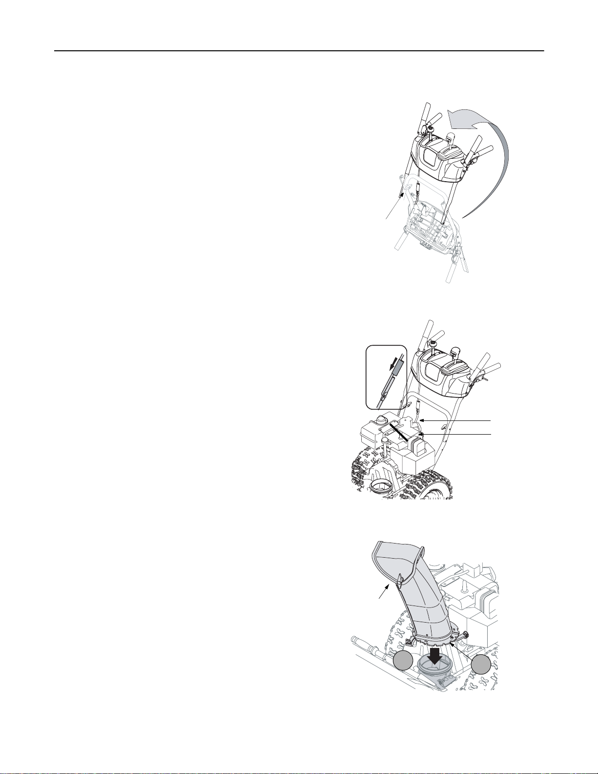
• When connecting the power cord, always connect
cord to starter on engine first, then plug the other
end into a three-hole grounded receptacle.
• When disconnecting the power cord, always
unplug the end from the three-hole, grounded
receptacle first.
2. Attach spark plug wire to spark plug.
3. Make sure that theauger drive and the traction
drive levers are in the disengaged position.
4. Move throttle control lever to FAST position.
5. Push key into the ignition slot. Make sure it snaps
into place. Do not turn key.
6. Rotate the choke knob to FULL choke position.
7. Push the primer three times.
8. Connect power cord to switch box on the engine.
9. Plug the other end of the power cord into a three-
hole, grounded 120 volt A.C. receptacle.
10. Push down on the starter button until the engine
starts. Do not crank for more than 10 seconds at a
time. This electric starter is thermally protected. If
overheated, it will stop automatically and can be
restarted only when it has cooled to a safe
temperature (a wait of 5 -10 minutes is required).
11. When the engine starts, release the starter button
and slowly rotate the choke to OFF position. If the
engine falters, rotate the choke to FULL and then
gradually to OFF.
12. Disconnect the power cord from the receptacle first
and then from the switch box on the engine.
13. Allow the engine to warm up for a few minutes
because the engine will not develop full power until
it reaches operating temperature. Operate the
engine at full throttle (FAST) when throwing snow.
Warm Start
1. If restarting a warm engine, rotate choke to OFF
instead of FULL and press the starter button.
Recoil Starter
Make sure that the engine has sufficient oil and the
auger drive and the traction drive levers are released.
Cold Start
1. Move throttle control to FAST position.
2. Push key into the ignition slot so that it snaps into
place. Do not turn key.
3. Rotate choke control to FULL choke position.
4. Push the primer button while covering the vent hole.
Remove your finger from the primer between primes.
Do not prime if temperature is above 50oF (10oC);
prime two times between 50oF (10oC) and 15oF
(-9oC); and prime four times below 15oF (-9oC).
5. Pull the starter handle rapidly. Do not allow the
handle to snap back, but allow itto rewind slowly
while keeping a firm hold on the starter handle.
6. As the engine warms up and begins to operate
evenly, rotate the choke knob slowly to OFF
position. If the engine falters, return to FULL choke,
then slowly move to OFF choke position.
7. Allow the engine to warm up for a few minutes
because the engine will not develop full power until
it reaches operating temperature.
8. Operate the engine at full throttle (FAST) when
throwing snow.
Warm Start
1. If restarting a warm engine after a temporary shut
down, rotate choke to OFF instead of FULL and do
not prime. Pull starter handle as instructed earlier.
Frozen Recoil Starter
If the starter is frozen and will not turn the engine,
proceed as follows:
1. Pull as much rope out of the starter as possible.
2. Release the starter handle and let it snap back
WARNING: The electric starter must be
properly grounded at all times to avoid the
possibility of electric shock which may be
injurious to the operator.
WARNING: If your house wiringsystemisnot
a three-wire grounded system, do not use this
electric starter under any conditions.