Westgate DV48 User manual

50-2003
SHERWOOD INDUSTRIES IS AN ENVIRONMENTALLY RESPONSIBLE COMPANY. THIS MANUAL IS PRINTED ON RECYCLED
PAPER.
B Y : S H E R W O O D I N D U S T R I E S L T D
BY: SHERWOOD INDUSTRIES LTD
OWNER’S
MANUAL
PLEASE KEEP THESE INSTRUCTIONS FOR FUTURE REFERENCE
DV48
This appliance may be installed in an
after-market permanently located,
manufactured (mobile) home,
where not prohibited by local codes.
This appliance is only for use with
the type of gas indicated on the
rating plate. This appliance is not
convertible for use with other gases,
unless a certified kit is used.
WHAT TO DO IF YOU SMELL GAS
• Open windows/extinguish any open
flame.
• Do not try to light any appliance.
• Do not touch any electrical switch
or use any phone in your building.
• Immediately call your gas supplier
from a neighbour’s phone. Follow
the gas supplier’s instructions.
• If you cannot reach your gas
supplier, call the fire department.
WARNING: If the information in this manual is
not followed exactly, a fire or explosion may result
causing property damage, personal injury or loss of
life. Installation and service must be performed by a
qualified installer, service agency or the gas supplier.
FOR YOUR SAFETY: Do not store or use gasoline or
other flammable vapours and liquids in the vicinity of
this or any other appliance.
Massachusetts installations (Warning): This product must be installed by a licensed plumber or
gas fitter when installed within the Commonwealth of Massachusetts. Other Massachusetts code
requirements: Flexible connector must not be longer than 36in., a shut off valve must be installed;
only direct vent sealed combustion products are approved for bedrooms/bathrooms. A carbon
monoxide detector is required in all rooms containing gas fired direct vent appliances. The fireplace
damper must be removed or welded in the open position prior to installation of a fireplace insert.
INSTALLER:
Leave this manual with the appliance.
CONSUMER:
Retain this manual for future reference.
WARRANTY REGISTRATION
enviro.com/warranty

FOR SAFE INSTALLATION AND OPERATION OF YOUR “WESTGATE”
HEATER, PLEASE CAREFULLY READ THE FOLLOWING INFORMATION:
• All Westgate gas-fired appliances must be
installed in accordance with their instructions.
Carefully read all the instructions in this manual first.
Consult the building authority having jurisdiction to
determine the need for a permit prior to commencing
the installation.
• NOTE: Failure to follow these instructions could
cause a malfunction of the fireplace, which could
result in death, serious bodily injury, and/or property
damage.
• Failure to follow these instructions may also void
your fire insurance and/or warranty.
GENERAL
• Installation and repair should be done by a
qualified service person. The appliance should be
inspected before the first use and, at least, annually
by a qualified service person. More frequent cleaning
may be required due to excessive lint from carpeting,
bedding material, etc. It is imperative the control
compartments, burners and circulating air passageways
of the appliance be kept clean.
• Due to high temperatures, the appliance should
be located out of high traffic areas and away from
furniture and draperies.
Children and adults should be alerted to the
hazards of high surface temperatures and
should stay away to avoid burn or clothing
ignition.
• Young children should be carefully supervised when
in the same room as the appliance. Toddlers, young
children and others may be susceptible to accidental
contact burns. A physical barrier is recommended if
there are at risk individuals in the house. To restrict
access to a fireplace or stove, install an adjustable
safety gate to keep toddlers, young children and other
at risk individuals out of the room and away from hot
surfaces.
• Clothing or other flammable materials should not
be placed on or near the appliance.
FOR YOUR SAFETY
• Installation and service must be performed by a
qualified installer, service agency or gas supplier.
• This installation must conform to local codes or,
in the absence of local codes, to the current CAN/
CSA-B149.1 Natural Gas and Propane Installation
Code (Canada) or National Fuel Gas Code ANSI
Z223.1.2 (USA)
• To prevent injury, do not allow anyone who is
unfamiliar with the stove to operate it.
•To prevent injury, if the pilot or pilot and
burners have gone out on their own, open the
glass door and wait 5 minutes to air out before
attempting to re-light the stove.
• Always keep the area around these appliances
clear of combustible material, gasoline and other
flammable liquids and vapours.
• These appliances should not be used as a drying
rack for clothing or for hanging Christmas stockings/
decorations.
• Due to the paint curing on the stove, a faint odor
and slight smoking will likely be noticed when the stove
is first used. Open a window until the smoking stops.
Always connect this gas stove to a vent system and
vent to the outside of the building envelope. Never
vent to another room or inside the building. Make sure
the specified vent pipe is used, properly sized and of
adequate height to provide sufficient draft. Inspect
the venting system annually for blockage and signs of
deterioration.
WARNING: Failure to position the parts in accordance
with the diagrams in this booklet, or failure to use only
parts specifically approved with this appliance, may
result in property damage or personal injury.
WARNING: Do not operate with the glass front
removed, cracked or broken. Replacement of the
glass should be done by a licensed or qualified service
person.
• Never use solid fuels such as wood, paper,
cardboard, coal, or any flammable liquids, etc., in this
appliance.
• Do not use this heater if any part has been under
water. Immediately call a qualified service technician
to inspect the heater and to replace any part of the
control or gas control systems that have been under
water.
• Do not abuse the glass by striking it or slamming
the door shut.
S AFETY PRECAUTIONS
2

TABLE OF CONTENTS
Safety Precautions..........................................................................................2
Table of Contents............................................................................................3
Codes And Approvals.......................................................................................4
Specifications.................................................................................................5
Dimensions........................................................................................5
Rating Label ......................................................................................6
Door Removal and Installation..............................................................7
Installation Set-Up...........................................................................................7
Firebox Liner Installation.......................................................................7
Log Burner / Ember Bed Installation.......................................................9
Log Set Installation............................................................................10
Glass Burner Installation.....................................................................12
Porcelain Panel Kit Installation............................................................14
Optional Front Installation..................................................................16
Start-Up & Operation.....................................................................................18
Normal Sounds During Operation.......................................................18
Remote Control Operations................................................................18
Technical Data..................................................................................18
System Description...........................................................................18
Wall Mounting The Receiver...............................................................20
Operating Procedure.........................................................................20
Air Shutter Adjustment......................................................................23
Check for Proper Burner Flame...........................................................24
Service / Maintenance....................................................................................25
Lighting Instruction Label..................................................................25
Air Intake.........................................................................................25
Light Bulb Replacement.....................................................................26
Cleaning / Annual Service..................................................................26
Cleaning The Glass...........................................................................26
Replacing Glass................................................................................26
Burner & Firebox Cleaning.................................................................26
Warranty......................................................................................................27
Installation Data Sheet..................................................................................28
3

DIRECT VENT ONLY: This type is identified by the prefix DV. This appliance draws all of its air for
combustion from outside the dwelling, through a specially designed vent pipe system.
This appliance has been tested and approved for installations from 0 feet to 4500 feet (1372 m) above
sea level.
In the USA: The appliance may be installed at higher altitudes. Please refer to your American Gas
Association guidelines which state: the sea level rated input of Gas Designed Appliances installed at
elevations above 2000 (610 m) feet is to be reduced 4% for each 1000 feet (305 m) above sea level.
Refer also to National Fuel Gas Code, ANSI Z223.1/ NFPA 54, local authorities, or codes which have
jurisdiction in your area regarding the de-rate guidelines.
In Canada: When the appliance is installed at elevations above 4500 feet (1372 m), the certified high
altitude rating shall be reduced at the rate of 4% for each additional 1000 feet (305 m). Refer also
to CSA-B149.1 Natural Gas and Propane Installation Code, local authorities, or codes which have
jurisdiction in your area regarding the de-rate guidelines.
• This appliance has been tested by INTERTEK TESTING SERVICES NA LTD. and found to comply
with the established VENTED GAS FIREPLACE HEATER standards in CANADA and the USA as follows:
VENTED GAS FIREPLACE HEATER (DV48; NG/LPG)
TESTED TO: ANSI Z21.88a-2007/CSA 2.33a-2007 VENTED GAS FIREPLACE HEATERS
CAN/CGA 2.17-M91 GAS FIRED APPLIANCES FOR HIGH ALTITUDES
CSA P.4.1-02 TESTING METHOD FOR MEASURING ANNUAL FIREPLACE EFFICIENCY
This Westgate DV48 Fireplace:
• Has been certified for use with either natural or propane gases. (See rating label.)
CODES AND APPROVALS
• Is not for use with solid fuels.
• Is approved for bedroom or bed sitting room. (IN CANADA: must be
installed with a listed wall thermostat. IN USA: see current ANSI Z223.1
for installation instructions.)
• Must be installed in accordance with local codes. If none exist, use current
installation code CAN/CSA-B149.1 Natural Gas and Propane Installation
Code (Canada in Canada or ANSI Z223.1/NFPA 54 in the USA.
• Must be properly connected to an approved venting system and not connected
to a chimney flue serving a separate solid-fuel burning appliance.
• The flow of combustion and ventilation air not be obstructed.
IMPORTANT NOTICE (Regarding first fire up): When the unit is turned
on for the first time, it should be turned onto high without the fan on for
the first 4 hours. This will cure the paint, logs, gasket material and other
products used in the manufacturing process. It is advisable to open a
window or door, as the unit will start to smoke and can irritate some people.
After the unit has gone through the first burn, turn the unit off including the
pilot, let the unit get cold then remove the glass door and clean it with a
good gas fireplace glass cleaner, available at your local WESTGATE dealer.
4

4”
(101mm)
20”
(508mm)
RATING LABEL LOCATION:
SPECIFICATIONS
DIMENSIONS:
Figure 1. Dimensions of the Firebox.
The Rating and Lighting instruction label is located below the door
frame, underneath the firebox attached to a chain. To access the label,
slide the plate forward out from under the firebox. Always return it
when finished.
Figure 2. Rating/Lighting Label Location.
5

6
SPECIFICATIONS
RATING LABEL:
Figure 3. Rating Label.
ELECTRICAL RATING:(EXIGENCES ÉLECTRIQUES)
Fan type circulator (Ventilateur circulaire) : 120 volts AC 60 hz / Less than 7 Amperes
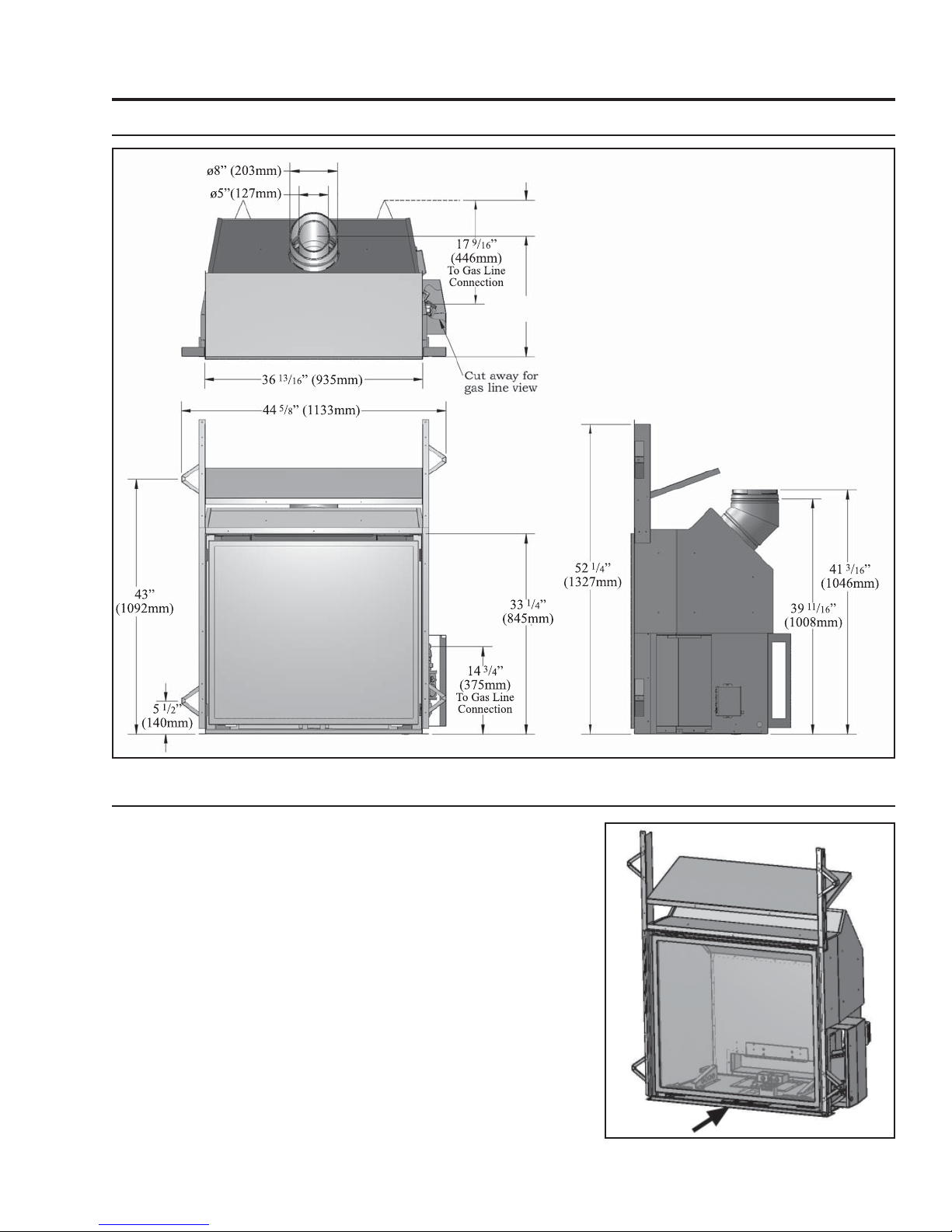
CLEARANCES TO COMBUSTIBLES: (DISTANCE OBLIGATOIRE DES COMBUSTIBLES)
Stove side (Côté de poêle): 4 inches (10.2cm), Back (Arriére): 4 inches (10.2cm), Ceiling from bottom of unit (Du fond
d'unité au Plafond): 80” inches (203.2cm), From fireplace frame to side wall (Du frome de la cheminée au mur latéral): 10"
(25.5 cm), From base of the unit to shelf, header, or 12" (30.5cm) mantel (De la base de l'unité à une étagère, un en-tête,
ou un 12" manteau de cheminée): 52.25" (133cm)
VENT PIPE CLEARANCES:(ESPACES LIBRES DE VENTILATION) See manufacturer’s listing, label and installation
instructions. Verifeez l’identifaction, l’etiquette et les instructionsd’installation du fabricant. This appliance must be properly
connected to a venting system in accordance with the manufacturer's installation instructions. Cet appareil doit être
convenablement connecté à un système donner vent conformément aux instructions d'installation du fabricant.
VENTED GAS FIREPLACE HEATER - NOT FOR USE WITH SOLID FUELS.
MAY BE INSTALLED IN
BEDROOM OR BEDSITTING ROOM (IN CANADA with a listed wall thermostat). THIS APPLIANCE MUST BE PROPERLY
CONNECTED TO A VENTING SYSTEM. ONLY FOR DIRECT DISCHARGE WITHOUT DUCT CONNECTION. This
appliance must be installed as per manufacturers installation instructions and in accordance with local codes if any. If none
exist, use current installation code CAN/CSA B149.1 in Canada or ANSI Z223.1/NFPA 54 in the USA. This vented gas
fireplace is not for use with air filters. FOR USE WITH GLASS DOORS CERTIFIED WITH THE APPLIANCE ONLY. This
appliance is only for use with the type(s) of gas indicated on the rating plate. A conversion kit is available for this appliance.
This appliance is not convertible for use with other gases, unless a certified kit is used.
Sections of the venting system
have not been installed. WARNING: Do not operate the appliance until all sections have been assembled
and installed in accordance with the manufacturers instructions.
FOYER AU GAZ A EVACUATION - NE PAS EMPLOYER AVEC DES COMBUSTIBLES SOLIDES.
Cet
appareil peut être installé dans une chambre à coucher ou un studio. Cet appareil doit être branché correctement à un
système de conduits. Uniquement pour l'échappement direct sans raccord de conduit.Cet appareil doit être installé selon les
directives d'installation du manufacturier et selon les codes locaux, s'il y a lieu. Autrement, employez le code d'installation
en vigueur au Canada CAN/CSA B149.1. Ne pas utilliser de filtre a air avec ce foyer au gaz a evacuation. POUR L'USAGE
AVEC PORTES VITREES A CERTIFIE AVEC L'APPAREIL SEULEMENT. Cet apperareil doit etre utilise uniquement avec
le type de gaz indique sur la plaque. Cet appareil ne peut etre converti a d’autres gaz sauf si une trouse de conversion
certifee est utilisee.
ADVERTISSEMENT: Ne pas utiliser l’appareil tant que toutes les sections n’ont pas ete
assemblees et installees selon les instructions du fabricant.
MOBILE HOME: May be installed in an aftermarket, permanently located, manufactured home (USA only) or mobile home,
where not prohibited by local codes. See owner's manual for details. This appliance must be installed in accordance with the
current Standard for Mobile Homes, CAN/CSA Z240, or the Manufactured Home Construction and Safety Standard, Title 24
CFR, Part 3280, or when such standard is not applicable, the current Standard for Fire Safety Criteria for Manufactured
Home Installations, sites, and Communitties, ANSI/NFPA 501A.
LA MAISON MOBILE :
Peut être installé dans une maison mobile. Cet appareil doit être installé conformement aux Normes actuelles
pour Maisons Mobiles, le BOITE/CSA Z240, ou les Normes de Construction et de Sureté des Maisons Pré-fabriquées (Titre 24 CFR, la
Partie 3280). Quand ces Normes ne sont pas en vigueur, il faut suivre les criteres pour la sureté (contre les increndies) et pour la
construction des Maisons Pré-fabriquées, leurs sites, ANSI/NFPA 501A, et des communautées aux Instructions du manufacturier.
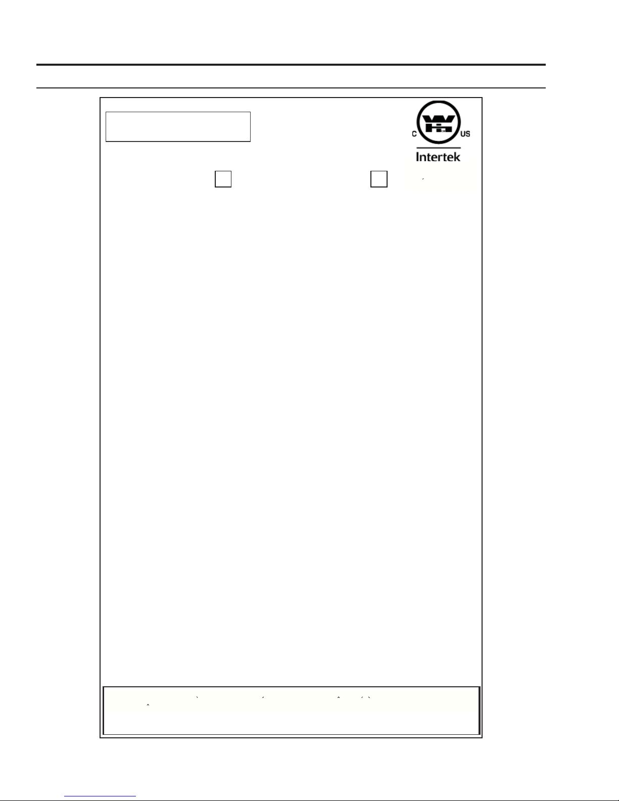
MANUFACTURED BY (FABRIQUE PAR) : SHERWOOD INDUSTRIES LTD. 6782 OLDFIELD RD. SAANICHTON, BC, CANADA
WH-
DV48
VENTED GAS FIREPLACE HEATER ENVIRO MODEL:
FOYER AU GAZ A EVACUATION MODELE ENVIRO:
TESTED TO / TESTÉE SELON LES NORMES:
ANSI Z21.88a-2007/CSA 2.33a-2007 VENTED GAS FIREPLACE HEATERS / FOYER AU GAZ EVACUATION;
CAN/CGA 2.17-M91 GAS FIRED APPLIANCES FOR HIGH ALTITUDES / LES APPAREILS BRULANT GAZ POUR
UTILISATION EN HAUTES ALTITUDES; Can/CSA P.4.1-02 (R2006) TESTING METHOD FOR MEASURING ANNUAL
FIREPLACE EFFICIENCY / LA METHODE D'ESSAI POUR MESURER L'EFFICACITE DE CHEMINEE ANNUELLE.
INPUT (ENTRÉE): NAT: 0-4500 FT (1372 M) MAX: 48,000 BTU (14.07 KW•h)
MIN: 16,000 BTU (4.68 KW•h)
LPG: 0-4500 FT (1372 M) MAX: 48,000 BTU (14.07 KW•h)
MIN: 17,000 BTU (4.98 KW•h)
MANIFOLD PRESSURE (PRESSION D’ADMISSION):
NAT: 3.5 in. WC (0.87kPa) / 1.6 in. WC (0.40kPa) LPG: 10 in. WC (2.48kPa) / 6.4 in. WC (1.59kPa)
MINIMUM GAS SUPPLY PRESSURE: (PRESSION MINIMALE D'ALIMENTATION DE GAZ PERMISE)
NAT: 5 in. Wc (1.24kPa) LPG: 12 in. Wc (2.98kPa)
ORIFICE SIZE: (DIMENSIONS DE L’ORIFICE)
NAT: Left # 45 DMS, Right # 41 DMS LPG: Left # 55 DMS, Right # 53 DMS
PILOT ORIFICE SIZE: (DIMENSIONS DE PILOTER L’ORIFICE)
NAT: # 62 DMS LPG: Left # 35 DMS
NAT: (Gaz naturel) LPG (Propane)
DUE TO HIGH SURFACE TEMPERATURES KEEP CHILDREN, CLOTHING, AND FURNITURE AWAY
DUES AUX TEMPERATURES ELEVEES, GARDEZ LES ENFANTS, LES VETEMENT ET LES MEUBLES ELOIGNES
DATE OF MANUFACTURE: DATE DE FABRICATION:
J F M A M J J A S O N D 2009 2010 2011 2012
DO NOT REMOVE THIS LABEL / N'ENLEVEZ PAS CETTE ETIQUETTE
DV48
WH# 16354
Certified for use in Canada & USA
Certifie pour installation au
Canada et aux Etats-Unis
CAUTION: Hot while in operation. Do not touch. Keep children, clothing, furniture, or gasoline and other liquids having flammable
vapours away. ATTENTION: Tres chaud quand allume. Ne touchez pas, les brulures severes peuvent resulter. Tenez loin des
enfants, des vetements, des meubles, de l’essence ou d’autres fluides produisant des vapeurs inflammables.

INSTALLATION SET-UP
DOOR REMOVAL AND INSTALLATION:
1) The fireplace door is hung on two (2) hooks on the top of the
firebox. The two (2) door latches at the bottom of the firebox
hook over the tabs on the bottom of the door frame.
2) Lower the door latch tool underneath the door frame. Catch
the lower door latch with the door latch tool (see Figure
5) and pull it out slightly, then down. Once the lower door
latch clears the tab on the bottom of the door frame, release
it inwards and then remove the door latch tool. Refer to
Figures 6 & 7.
3) Pull the Door Frame at the bottom forward about 2” (5cm),
then lift the Door Frame upwards to clear the Upper Door
Figure 4: Door Latch /Air Adjustment Tool.
Figure 6: Door Latch Tool in Place.Figure 5: Door Latch Locations.
7
Hooks. Refer to Figures 7 & 8.
4) Lift the Door Frame away, being
careful that the glass panel is
secure within the Door Frame.
Figure 8: Top Door Hook.
Figure 7: Door Latch Locations.
FIREBOX LINER INSTALLATION:
IMPORTANT: The paint on the panels may fade for the first 8-10 hours of burn time, but will come back to
its color after the paint has cured. The paint is very delicate and handing them with care is necessary not to
mark or smudge the paint.

8
Figure 9: Rear Brick Panel Support.
INSTALLATION SET-UP
Figure 10: Rear Firebox Liner Panel in Place.
Figure 11: Left Firebox Liner
Panel on Front Edge of Firebox. Figure 12: Left Firebox Liner Panel in Place.
Figure 13: Top Firebox Liner Panel in Place. Figure 14: Right Firebox Liner Panel in Place.
1. Prior to installing the firebox liners, you will need to ensure the
Rear Brick Panel Support is in the correct position. The support
is located at the back of the firebox (see Figure 9) and can be
installed in two (2) positions. The upper position (using the lower
screw holes) is for the October Panels. The lower position (using
the upper screw holes) is for the Sandstone, Ledgestone, and
Porcelain Panels. Remove the Support, if necessary, and move it to
5. Install the Top Panel by
placing it on top of the
Rear Panel and behind the
Left Panel (see Figure 13).
Hold it with one hand or
have someone else hold
it for you while you place
the last panel. WARNING:
If this panel falls from this
location it will possibly
break or the paint work will
become chipped.
6. Place the Right Firebox Liner
Panel in the same manner
used for the Left Panel (see
Figure 14). The
vertical edges
of the left and
right panels
should line up
with the front
edges of the
firebox sides.
The side panels
rest up against
the back panel
and hold the
top panel in
position.
the appropriate
placement.
2. Ensure the light covers provided with your kit are installed on
the Light Cover Bases at the rear of the firebox. The tabs on the
back of the Light Cover slide down behind the light cover base.
Refer to Figures 44 and 45.
3. Install the Rear Firebox Liner. This panel fits around the accent
lights and rests on top of the Rear Brick Panel Support. It will
stay in this location as you install the remaining panels. Refer to
Figure 10.
4. Install the Left Firebox Liner Panel; it sits on the bottom front
edge of the firebox (see Figure 11 & 12), a support bracket at
the lower rear of the firebox, and is held in by a retainer at the
top of the firebox. Adjust the panel retainers as required.

INSTALLATION SET-UP
LOG BURNER / EMBER BED INSTALLATION:
1. Use the two (2) T-20 screws provided; install the rear burner shield onto the back of the burner. The
mounting holes are just above the mixing tubes at the rear of the burner, refer to Figure 15.
Figure 15: Installing Rear Burner Shield. Figure 16: Burner Mounting Brackets.
Figure 17: Log Burner Over Pilot Assembly.
9
2. In the bottom rear of the firebox there are
two (2) gas orifices in a housing that facilitate
the air shutter mechanisms and the Burner
Mounting Brackets are above them (See
Figure 16). There are two (2) mixing tubes
underneath the back of the burner (see
Figure 15). Lift the burner into the firebox
with the back of the burner tilted downward.
Keep the burner high enough at the front to
clear the pilot assembly. Line up the mixing
tubes with the holes in the burner mounting
brackets and slowly lower the front of the
burner over the pilot assembly (see Figure
17).
Figure 18: Log Burner in Place.
Figure 19: Burner Accents Pieces in Place.
3. Pull the burner forward up to the angular brackets near
the front of the firebox (see Figure 18).
IMPORTANT: If the burner is not far enough back
to lower the burner behind these brackets, then the
mixing tubes are not engaged in the air shutter. Failing
to ensure the mixing tubes are located in the mixing
tube support brackets may cause serious performance
and or safety issues.

10
INSTALLATION SET-UP
Figure 21: Tab on Firebox Grate.Figure 20: Slot for Firebox Grate.
4. Install the burner accent pieces as shown in
Figure 19. There are a left, a right and a front
ceramic trim. On each side of the burner and
on the inside of each burner side accent pieces
there is a slot, which should be aligned in order
to position the log grate correctly (see Figure
18).
5. The firebox grate has two (2) tabs that run
below the feet of the grate (see Figure 21),
place the grate over the burner top and carefully
inserting the grate tabs into the slots on the
burner (see Figure 20 & 22). Once the grate is
installed correctly, the burner, grate, and side
burner accents will be all locked together.
Figure 22: Firebox Grate in Place.
LOG SET INSTALLATION:
IMPORTANT: The paint on the logs may fade for the first 8-10 hours of burn time, but will come back to its
color after the paint has curred. The paint is very delicate and handing them with care is nessesary not to
mark or smuge the paint.
1. Install Right Rear Log. The right side sits on the
grate with the groove on the bottom of the log
fitting onto the top of the grate (see Figure 23).
Insert the log pin into the top of the ember burner (see A in Figure 23). Align the log front edge with the
front section of the grate (see B in Figure 23).
Figure 23: Log 1 in Place.
Figure 24: Log 2 in Place.

Figure 25: Log 3 in Place. Figure 26: Log 4 in Place.
2. Install Left Rear log with the right side on the grate,
using a groove on the bottom of the log to index
itself to the grate (see Figure 24). The right side
self locates on the first log. Alignment notches
are provided for locating the centre area (see C in
Figure 24). Align the front edge of the log with the
upright section of the log grate (see D in Figure
24).
3. Insert Log 3 into the groove on the burner top. The
groove has a stop at the rear to position the log
properly from front to back. Refer to Figure 25.
4. Log 4 sits in a groove molded into the top of the
burner top. See the details in Figure 26 showing the
indexing key on this log.
Figure 27: Log 5 in Place.
11
6. Install Log 6 by resting it across the flat section of Log 5 and locating the front edge across the grate finger
as shown in Figure 28.
7. Log 7 sits in between the left panel and the left grate finger and cross the bar of the grate (see Figure 29).
There is a notch across Log 2, which this log will locate into. The edge along the back of this log will index
into the notch of Log 2.
Figure 28: Log 6 in Place. Figure 29: Log 7 in Place.
INSTALLATION SET-UP
5. Install Log 5 with the right side resting on the grate and the right side right up against the right hand
firebox liner. The left side sits on a flat section in Log 3. Refer to Figure 27.

12
INSTALLATION SET-UP
Figure 30: Log 8 in Place. Figure 31: Log 9 in Place.
8. Situate Log 8 between the right grate
finger, the right firebox liner and the grate
cross bar (see Figure 30). On the back of
the log near the top end is a ceramic pin,
this pin sits into a groove on the top of Log
2.
9. Sit the Y shaped Log 9 across Log 4 and 5
as shown in Figure 31.
10. The final little Accent Twig sits on the front
ceramic burner accent and the grate finger
as shown in Figure 32.
NOTE: Variances in gas quality or log
placement may cause some discoloration
of the log set to occur.
Figure 32: Accent Twig in Place.
GLASS BURNER INSTALLATION:
Figure 33: Mixing Tubes in Glass Burner.
Figure 34: Placing Glass Burner.
1. In the bottom rear of the firebox there are two (2)
gas orifices in a housing that facilitate the air shutter
mechanisms and the Burner Mounting Brackets are above them (See Figure 16). There are two (2) mixing
tubes underneath the back of the burner (see Figure 33). Lift the burner into the firebox with the back of
the burner tilted downward. Keep the burner high enough at the front to clear the pilot assembly. Line up
the mixing tubes with the holes in the burner mounting brackets and slowly lower the front of the burner
over the pilot assembly (see Figure 34).

2. Pull the burner forward up to the angular brackets near the front
of the firebox (see Figure 35). The burner rests on the floor of the
firebox and is properly aligned against the two (2) front burner
rests.
IMPORTANT: If the burner is not far enough back to lower the
burner behind these brackets, then the mixing tubes are not
engaged in the air shutter. Failing to ensure the mixing tubes are
located in the mixing tube support brackets may cause serious
performance and or safety issues.
3. Place the glass tray over top of the burner top as shown in Figure
36. It simply rests over the top section of the burner.
4. In front of the pilot assembly, on the front edge of the burner is
one burner port which helps in the lighting of the
main burner (see Figure 35). The glass tray has
one hole in the same position that allows the gas
to flow to this location. Ensure the glass tray hole is
properly positioned over the port in the burner.
5. The DV48 glass burner option is supplied with two
(2) quantities of glass, black and white. There is
enough of either to fill the burner, so you can decide
whether to install all white, all black, or some type
of mixture (example in Figure 37). Fill the glass
burner tray to the top. Try to keep glass from falling
in around the pilot assembly.
Figure 35: Glass Burner in Place.
Figure 36: Glass Tray over Burner.
13
Figure 37: Glass Tray with Mixed Glass. Figure 38: Burner Trim Being Placed.
Figure 39: Burner Trim in Correct Position. Figure 40: Proper Gap Between The Glass Tray And
The Burner Trim.
INSTALLATION SET-UP

14
6. Gently place the burner trim piece around the burner (see Figure 38). It sits on various support brackets
and fits around the burner tray and up against the firebox liner. Figure 39 shows the burner trim in the
correct position. Ensure a minimum ⅜” (8mm) gap is maintained around the burner glass tray (see Figure
43).
7. If the optional rock accent kit was purchased for the DV48, you can place the rocks in a random pattern
around the glass tray. A few can straddle the ⅜” (8mm) gap around the glass tray. Try to keep them
INSTALLATION SET-UP
Figure 42: Example of Rock Placement - Multiple Kits. Figure 43: Keep Area in Front of Pilot Assembly Clear.
2. Ensure the Rear Brick Panel
Support is in the lower position.
The support is located at the
back of the firebox (see Figure
9). Remove the Support, if
necessary, and move it to the
appropriate placement.
3. Install the Rear Firebox Liner.
This panel rests on top of the
accent lights and Rear Brick
Panel Support. It will stay in
this location as you install the
remaining panels. Refer to Figure
46.
PORCELAIN PANEL KIT INSTALLATION:
1. Install the porcelain Light Covers over the Light Cover Base. The tabs on the back of the Light Cover slide
down behind the Light Cover Base. Refer to Figures 44 & 45.
Figure 44: Porcelain Light Covers in Place. Figure 45: Porcelain Light
Covers Close-up.
looking randomly placed. Keep from placing them
in large piles as they need to be evenly distributed.
Examples are shown in Figure 41 & 42.
It is important that rock accents are not placed in
front or over the pilot assembly. This may prevent
the burner from lighting in a timely fashion or
overheat the pilot assembly. Keep an area of about
3” (75mm) in front of the pilot light free from
obstruction and rock accents (see Figure 41).
Figure 41: Example of Rock Placement - Single Kit.

Figure 46: Rear & Left Porcelain Panels in Place. Figure 47: Top Porcelain Panel in Place.
15
4. Install the Left Firebox Liner Panel; it sits on the bottom front edge of the firebox (see Figure 46), a support
bracket at the lower rear of the firebox, and is held in by a retainer at the top of the firebox. Adjust the
panel retainers as required.
5. Install the Top Panel by placing it on top of the Rear Panel and behind the Left Panel (see Figure 47). Hold
it with one hand or have someone else hold it for you while you place the last panel. WARNING: If this
panel falls from this location it will possibly break or the paint work will become chipped.
Figure 48: Installing Left Burner Cover Support.
6. Place the Right Firebox Liner Panel in the
same manner used for the Left Panel. The
vertical edges of the left and right panels
should line up with the front edges of the
firebox sides. The side panels rest up against
the back panel and hold the top panel in
position.
7. Install the Left Burner Cover Support as
shown in Figure 50. This bracket is installed
using three (3) T-20 Torx screws supplied.
Install the Right Burner Cover Support Right
as you’ve done on the left side.
Figure 49: Permanent Magnet on Left Burner Cover Support.
INSTALLATION SET-UP
Figure 50: Slots in Back of Burner Cover.

16
INSTALLATION SET-UP
Figure 51 Installing Burner Cover.
8. Place one of the Permanent Magnets provided on the front edge of the Burner Cover Supports as shown in
Figure 49.
9. Install the Burner Assembly; refer to Step 1 & 2 of GLASS BURNER INSTALLATION.
10. Place the Ceramic Burner Front on top of the Burner Cover Supports as shown in Figure 49. This part
should be pulled forward until it contacts the metal brackets in the front.
OPTIONAL FRONT INSTALLATION:
There are many different styles of optional fronts available for your fireplace. These fireplace fronts hang onto
the front of your fireplace using four (4) hooks, one on each corner (refer to Figure 104). These hooks secure
the front to the fireplace, providing for easy removal for service access to the fireplace and also to position the
front the proper distance away from the glass door and the fireplace facing.
11. The Burner Cover has two (2) slots, one the either
side of the rear flange (refer to Figure 50). These
slots fit over the two (2) studs in the firebox (refer to
Figure 49) to keep it in place.
The arrows in Figure 51 point at the studs that hold
the Burner Cover in position. Place the Burner Cover
over the pins and then once aligned with the holes,
push the Burner Cover back towards the rear of the
firebox. The front of the Burner Cover is held in place
by the permanent magnets installed in step 8.
12. Install the Glass Tray and the Glass to complete the
installation of the Porcelain Panel Kit, refer to Step 3,
4, 5, & 7 of GLASS BURNER INSTALLATION.
Figure 52: Optional Front Parts. Figure 53: Optional Front Being Installed.

INSTALLATION SET-UP
Figure 54: Optional Front Installed.
17
Install the front by lifting it parallel to the
fireplace with the mounting bracket hooks
pointing towards the fireplace. Slide the
hooks all the way into the slots between
the Glass Door Frame and the drywall
flanges of the fireplace. Pull down on each
corner to make sure the hook is engaged
with the hanger. Refer to Figures 53 & 54.
IMPORTANT: Ensure that the minimum
gap required between the Optional Front
and wall of the unit is maintained (refer
to Figure 54). Not maintaining the proper
gap will cause the unit to run at elevated
temperatures and result in an unsafe
condition
The face should be cleaned before the
fireplace is turned on for the first time.

18
START-UP& OPERATION
NORMAL SOUNDS DURING OPERATION:
Table 1: Normal Sounds
Component Sound & Reason
DV48 & Fascia Creaking when heating up or cooling down.
Burner Light pop or poof when turned off; this is more common with LP units.
Pilot Flame Quiet whisper while the pilot flame in on.
Gas Control Valve Dull click when turning on or off, this is the valve opening and closing.
REMOTE CONTROL OPERATIONS:
The Proflame GTMF is a modular remote control system that directs the functions of the DV48. The Proflame
GTMF is configured to control the on/off main burner operation, its flame levels and provides on/off and Smart
thermostatic control of the appliance. The system controls a remotely actuated 120V/60Hz power outlet, fan speed
through six (6) levels and has a constantly powered 120V/60Hz power outlet.
WARNING
THE TRANSMITTER AND RECEIVER ARE RADIO FREQUENCE DEVICES. PLACING THE RECEIVER IN OR
NEAR METAL MAY SEVERELY REDUCE THE SIGNAL RANGE.
ATTENTION!
- TURN “OFF” THE MAIN GAS SUPPLY OF THE APPLIANCE DURING INSTALLATION OR MAINTENANCE
OF THE RECEIVER.
- PLACE THE RECEIVER’S 3 POSITION SLIDER SWITCH IN THE “OFF” POSITION DURING
INSTALLATION OR MAINTENANCE.
- TURN “OFF” MAIN GAS SUPPLY TO THE APPLIANCE PRIOR TO REMOVING OR REINSERTING THE
BATTERIES IN THE RECEIVER.
- DURING APPLIANCE INSTALLATION/MAINTENANCE OR IN CASE OF REMOTE CONTROL
MALFUNCTION TURN OFF THE FAN CONTROL MODULE USING THE “ON/OFF” MAIN POWER SWITCH
ON THE FRONT PANEL OF THE FCM.
TECHNICAL DATA
Transmitter (Remote Control):
Supply voltage 4.5 V (three 1.5 V AAA batteries)
Ambient temperature ratings 0 - 50 °C (32 - 122 °F)
Receiver:
Supply voltage 6.0 V (four 1.5 V AA batteries)
Fan Control Module:
Supply voltage/frequency: 120 V / 60 Hz
Aux switched output: 120 V / 60 Hz / 2 A
Fan speed output: 120 V / 60 Hz / 1 Art
SYSTEM DESCRIPTION:
The Proflame Remote Control System consists of three (3) elements:
1. Proflame Transmitter.
2. Proflame Receiver and a wiring harness to connect the Receiver to the gas valve, stepper motor and Fan Control
Module.
3. Proflame Fan Control Module (FCM)

START-UP& OPERATION
TRANSMITTER (Remote Control with LCD
Display)
The Proflame Transmitter uses a streamline
design with a simple button layout and
informative LCD display (Figure 55). The
Transmitter is powered by three (3) AAA type
batteries. A Mode Key is provided to Index
between the features and a Thermostat
Key is used to turn on/off or index through
Thermostat functions (Figure 55 & 56).
RECEIVER
The Proflame Receiver (Figure 57) connects directly
to the gas valve, stepper motor, DFC, and Fan
Control Module with a wiring harness. The Receiver is
powered by four (4) AA type batteries. The Receiver
accepts commands via radio frequency from the
Transmitter to operate the appliance in accordance
with the particular Proflame system configuration.
The Receiver three (3) position slider switch can be
set to one of three positions: ON (Manual Override),
Remote (Remote control), or Off.
Figure 55: Proflame Transmitter.
Figure 56: Proflame Transmitter LCD Screen.
Figure 57: Proflame Receiver.
19
FAN CONTROL MODULE
Fan Control Module (FCM) offers the added
ability to control the fan speed through six (6)
speeds, a remotely actuated 120V outlet and
a constantly powered 120V outlet. The FCM
provides DC power to the Receiver allowing the
batteries to be used only when line power is
interrupted or lost (see Figure 58).
Figure 58: Proflame Fan Control Module.

20
START-UP& OPERATION
WALL MOUNTING THE RECEIVER:
The receiver can be placed inside a standard Junction type wall box either by itself or in combination with a
light dimmer control. This installation can take place up to 8’ft (2.4m) from the appliance control valve.
1. Connect the wiring harness to the back of the
Receiver.
2. Install the Receiver in the Junction box using the
existing J box screws (Figure 59).
3. Insert the four (4) AA type batteries in the battery
compartment with the correct polarity.
4. Place the slider into the cover plate.
5. Put the Receiver switch in the “OFF” position.
6. Make sure the Receiver and cover plate words “ON”
and “UP” are on the same side.
7. Align the slider with the switch on the Receiver and
couple the switch into the slider.
8. Align the screw holes.
9. Using the two (2) screws provided secure the cover
plate to the Receiver.
OPERATING PROCEDURE:
Initializing The System For The First Time
Install the four (4) AA batteries into the receiver battery bay. Note the polarity of the battery and insert into
the battery bay as indicated on the Battery cover (+/-). Place the 3-position slider switch in the “Remote”
position (see Figure 57). Using the end of a paper clip, or other similar object, insert the end of the paper clip
into the hole marked “PRG” on the Receiver front cover (see Figure 57).
The Receiver will “beep” three (3) times to indicate that it is ready to synchronize with a Transmitter. Install
the three (3) AAA type batteries in the Transmitter battery bay, located on the base of the Transmitter. With
the batteries already installed in the Transmitter, push the ‘ON’ button. The Receiver will “beep” four (4)
times to indicate the Transmitter’s command is
accepted and sets to the particular code of that
Transmitter. The system is now initialized.
Temperature Indication Display
With the system in the “OFF” position, press the
Thermostat Key and the Mode Key at the same
time. Look at the LCD screen on the transmitter
to verify that a °C or °F is visible to the right of
the Room Temperature display (see Figure 60).
Turn on the Appliance
Press the ON/OFF Key on the Transmitter. The Transmitter display will show all active Icons on the screen. A
single “beep” from the Receiver will confirm reception of the command and will commence to first ignite the
pilot light, followed by the main burner. This should take about 10 seconds to complete.
Figure 59: Wall Mounting the Receiver.
Figure 60: Remote Control Display in Farenheit and Celcius.
Other manuals for DV48
4
Table of contents
Other Westgate Indoor Fireplace manuals
Popular Indoor Fireplace manuals by other brands

Valor
Valor BG C-1 owner's guide

Twin-Star International
Twin-Star International Chimney Free DFI020ARU operating manual

Valor
Valor 1200EAN Installation & operating instructions

EdilKamin
EdilKamin MYA ECO Installation, use and maintenance

Jøtul
Jøtul F 100 USA Installation and operating instructions

Rinnai
Rinnai Compact 2 Operation guide