Westinghouse TECO PA7300 Series Instruction manual

PA7300 INVERTER SERIES
Pump Quick Start Manual
Rev. 1.0 / Nov 27th 2007

PA7300 Inverter Pump Quick Start Manual
__________________________________________________________________
_______________________________________________________________
TECO – Westinghouse Motor Company 2
Quick Start Guide for Pump Applications
This guide is to simplify the start up of the PA7300 Inverter series for pump applications. It is not
intended to replace the PA7300 Installation and Operation Manual 4H358D0250007, and the user is
urged review this manual. There are three methods of control or combinations thereof that that may
be selected; Keypad, Analog Signal (external terminal) or Serial Communication. Only Keypad and
Analog Signal will be covered as Serial Communication is beyond the scope of this manual. For
Serial Communication control or special external control, the user is referred to the PA7300
Installation and Operating Manual.
SAFETY FIRST!
Step 1 - Before Starting the Inverter
• Referring to the PA7300 Instruction Manual, please review and verify that the correct inverter size
for the motor was received free of damage. To ensure personnel safety and to avoid equipment
damage, follow the precautions and the installation procedures for mounting, wiring, and operating
environment.
CAUTION - To avoid damage to the inverter when removing the inverter cover
and/or LCD Operator, refer to Appendix B for the proper procedure.
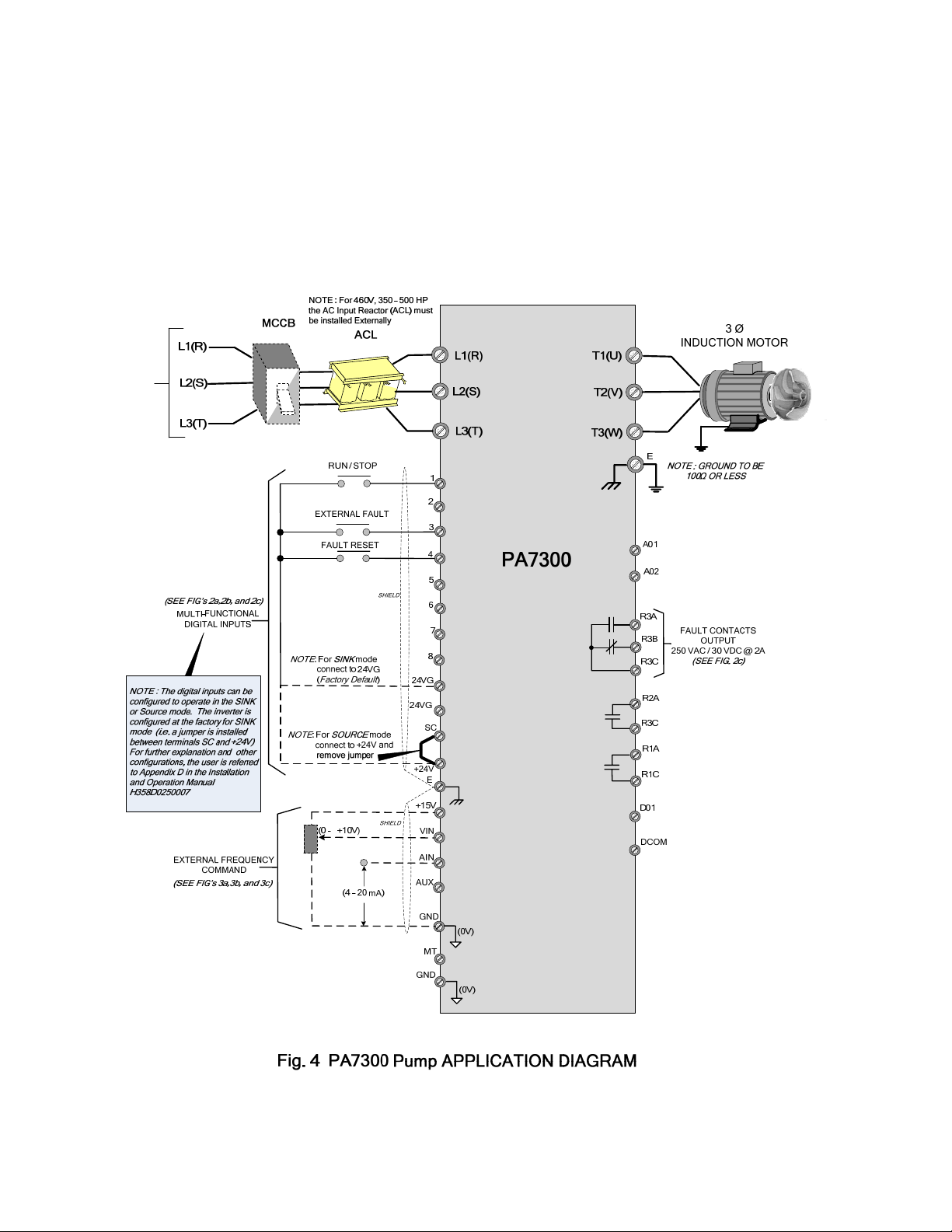
• In accordance applicable codes make electrical connections to the motor and input power
terminals. (Refer to the block diagram, Fig. 4). No other external connections should be made at
this time, as the initial control will be from the Keypad.
Step 2 - Apply Power to the Drive
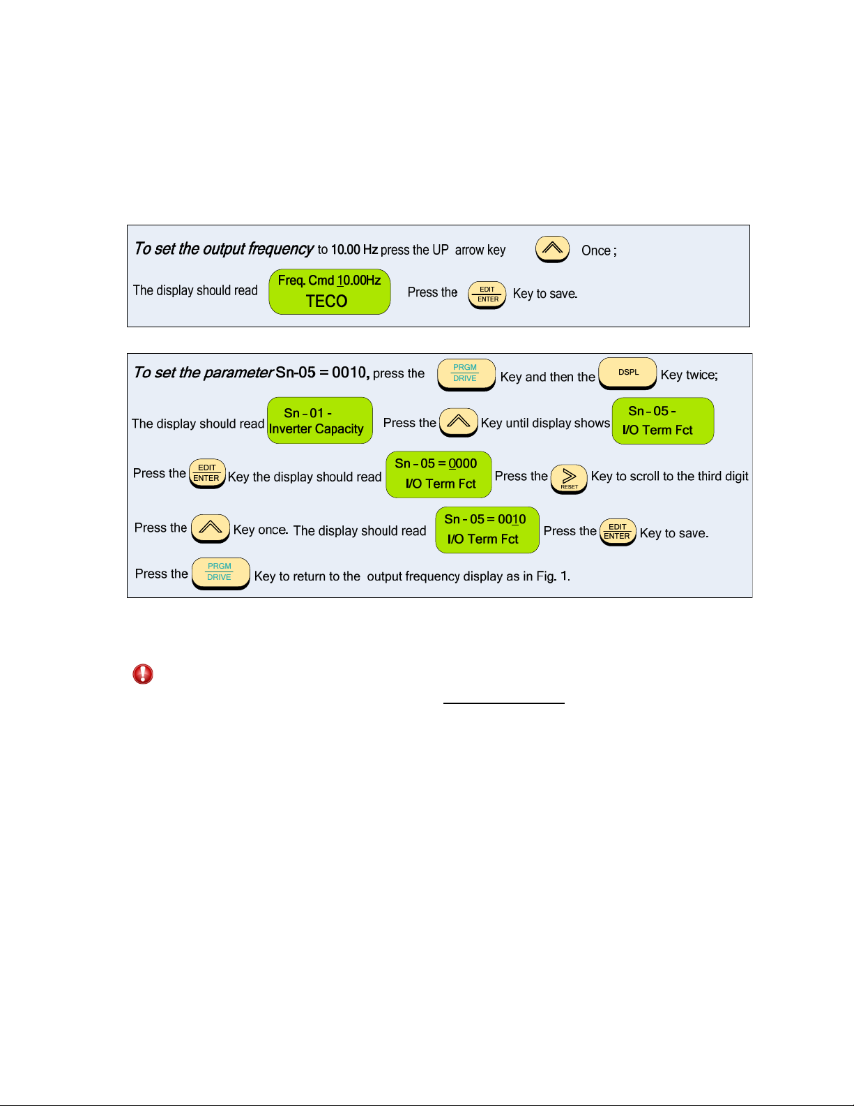
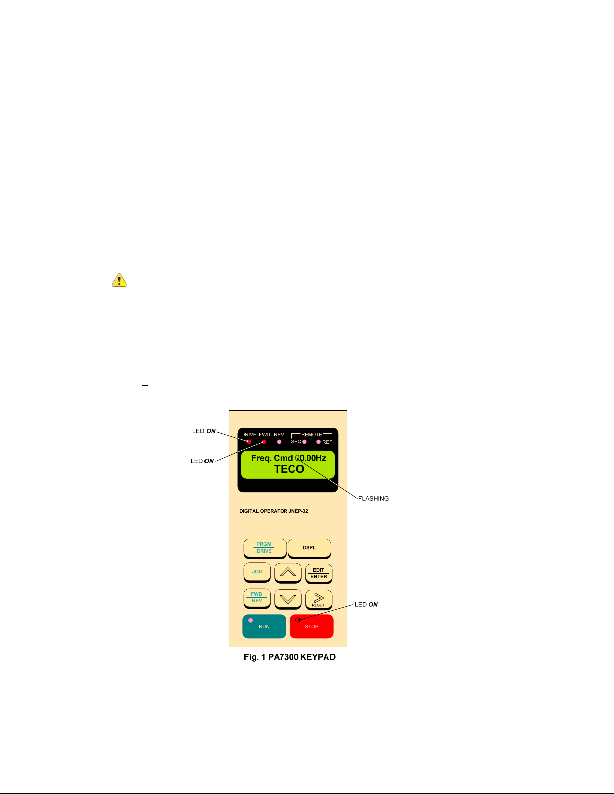
• Apply AC power to the Inverter and observe the LCD Display Line 1; it should read
“Freq. Cmd 00.00Hz”. Line 2 should read “TECO”. The red LED on the STOP key should be ON.
The DRIVE and FWD LED’s should be ON. (See Fig. 1 below)
Step 3 - Set Drive to Run Mode
• If the red DRIVE LED is not ON with AC power up, press the PGRM / DRIVE key until the red
Drive LED is ON. The Inverter is now in the RUN mode.

PA7300 Inverter Pump Quick Start Manual
__________________________________________________________________
_______________________________________________________________
TECO – Westinghouse Motor Company 3
Step 4 - Check Pump Motor Operation
•Enter 10.00Hz for the frequency reference and set parameter Sn-05 = 0010 to disable Reverse
Direction operation. Note: The output from the inverter is displayed in Hz as factory default. If
desired, the output may be displayed in per cent (%) of full speed. (see appendix)
•Press the RUN key, and check the pump direction of rotation. If the direction is not correct, press
the STOP key and wait until the pump has come to a complete STOP. Next, Power Down the
inverter.
Danger
After the power has been turned OFF, wait at least 5 minutes until the charge
indicator extinguishes completely before touching any wiring, circuit boards or
components.
•Reverse any two of the pump motor connections at the inverter ( U(T1),V(T2), or W(T3) ). Next,
following STEP 2, Power-up the inverter; the motor direction should now be correct.
Step 5 – Select Method of Control
•Before selecting the method of control, ensure the inverter is in the STOP mode.
•There are two methods of control or combinations thereof that may be selected; Keypad and
Analog Signal.
RUN / STOP Command - Can be provided from the keypad or from an external contact
(see Fig. 2a).
Speed Reference – Can be from the keypad or from an external analog signal (0 – 10 VDC or
4 – 20 mA). see Fig’s 3a,3b, and 3c.
•The method of control is set by parameter Sn – 04. The table on the next page shows the value
that Sn – 04 needs to be set for the various combinations of control.

PA7300 Inverter Pump Quick Start Manual
__________________________________________________________________
_______________________________________________________________
TECO – Westinghouse Motor Company 4
Parameter Sn – 04 =
Function Start / Stop Speed Reference
0011 Keypad Keypad
0001 External Contact Keypad
0010 Keypad External Analog
0000 External Contact External Analog
press the Key, and then the Key twice;
The display should read Press the Key until the display shows
Press the Key; the display should read 0To select the desired combination in
Key to scroll to the digit position and the
Press the to return to the output frequency display as in Fig. 1.
accordance with the table value, press the Key
to select, the digit value (0 or 1). After the selection press the Key to save.
•After the method of control has been selected, if external control wiring is required, (e.g. external
analog), Power Down the inverter before removing any covers or making any connections.
In the following pages are wiring examples for Start / Stop, E-Stop, Restart, and Analog
Connections.
Danger
After the power has been turned OFF, wait at least 5 minutes until the charge
indicator extinguishes completely before touching any wiring, circuit boards, or
components.

PA7300 Inverter Pump Quick Start Manual
__________________________________________________________________
_______________________________________________________________
TECO – Westinghouse Motor Company 5
DIGITAL INPUT / OUTPUT terminal connections
Fig’s 2a, 2b, and 2c below show the terminal connections for input control functions. The
connections shown are typical and the user is referred to the PA7300 Manual if additional
information is required. Fig. 2d shows an example for the use of the Fault Output Relay.
P2
FAULT RESET SWITCH
(MOMENTARY)
P2
24VG 234E
P1
1
Connect
shield to
terminal E
Fig. 2c Fault Reset switch connection
4
24VG 24VG 123
P1
RUN
STOP
START / STOP SWITCH
Connect
shield to
terminal E
E
Fig. 2a Start / Stop switch connection
EXTERNAL FAULT CONTACT
24VG 1233E
Connect
shield to
terminal E
N.O.
Fig. 2b External Fault contact connection
P1
Note :
This external Fault Reset input is
optional. The Fault may be also
reset from the keypad.
Note :
This external Fault input is optional.
It may be provided from any external
isolated dry contact source that is
required to shut the inverter down.
Note :
This external Start / Stop
switch is required when
“External Contact” is
selected in parameter Sn-04 .
(See Step 5)
P2
R2C R3A R3B R3C
Fig. 2c Fault output contacts
P2
N.O.
N.C.
Note :
Relay contacts are rated @
250 VAC, 30 VDC, 2A or less
External warning
device such as a
flashing lamp or
buzzer
POWER
SOURCE
NOTE:
This is an example of the
use of the Fault contacts.
They could also be used to
shut down equipment etc.

PA7300 Inverter Pump Quick Start Manual
__________________________________________________________________
_______________________________________________________________
TECO – Westinghouse Motor Company 6
ANALOG INPUT terminal connections
Fig’s 3a,3b, and 3c.show the various analog input schemes that can be used to control the
output frequency and thus the speed of the pump motor when External Analog is selected by
Sn-04 in STEP 5. Only one method may be used as the input source with Fig. 3a Potentiometer
Input being most common.
Fig. 3a Speed Control Potentiometer Input Fig. 3b 0 - +10 VDC Analog Input
EVIN AIN GND
15
2KΩ
SPEED CONTROL
POTENTIOMETER
Connect
shield to
terminal E
EAIN GND
15
E
0 - +10 VDC
0 - +10 VDC INPUT VOLTAGE SOURCE
+-
Connect
shield to
terminal E
Shielded
twisted Pair
Fig. 3b 4 – 20 mA Analog Input
EVIN GND
15
4 – 20 mA INPUT CURRENT SOURCE
+-
Connect
shield to
terminal E
Shielded
twisted Pair
4 – 20 mA
VIN
AIN

PA7300 Inverter Pump Quick Start Manual
__________________________________________________________________
_______________________________________________________________
TECO – Westinghouse Motor Company 7
PA7300 BLOCK DIAGRAM
Fig. 4 is an overall basic electrical connection diagram for the PA7300. It is used in conjunction
with the other sections of this guide to give the user the ability to successfully start up a Pump
application. More detailed information is available in the PA7300 Manual to which the user is
referred, if further information is required.

PA7300 Inverter Pump Quick Start Manual
__________________________________________________________________
_______________________________________________________________
TECO – Westinghouse Motor Company 8
Appendix A-
Changing display to read output speed in percent (%) of full speed.
The display is factory defaulted to show the inverter output frequency in Hz. If desired, the
display can be changed to show the output frequency as a percentage of full speed. To do this
parameter Cn-20 must be changed from (00000) to (00001) as follows:
press the Key, and then the Key 4 times;
The display should read Press the Key until display shows
Press the Key; the display should read 0Press the Key and scroll to the
last digit position and then press the Key; The display should read 1
Key to save.
Press the Press the to return to the main display.
Appendix B -
Removing the LCD Digital Operator and Inverter Cover(s)

Other manuals for TECO PA7300 Series
1
Table of contents
Other Westinghouse Water Pump manuals