WestwoodOne iPump 6420 User manual

DIGITAL AUDIO SERVER
QUICKSTART INSTALLATION
INSTRUCTIONS
Your receiver is programmed for Big D & Bubba
on audio & cue relay port 1. Once installed,
please contact network support for activation.
INTRODUCTION
This Quick Start guide instructs you on how to quickly set up and start operating
your i6420 Professional media server in order to receive WestwoodOne
programming. For additional information please go to
www.dg-tech.net
This receiver is a replacement using the same satellite, LNB and dish as your
existing receiver. Please expedite the installation of this receiver as it must be
installed and online no later the four weeks from the original ship date on your
packing list from the manufacturer.
Contact Network Services between 8AM and 10PM Eastern Monday through
Friday at (888) 435-7450 for:
•Installation Questions
•Authorization of the receiver after installation.
Version 1.00.00 11/15/11

EbNo should be above 10 (it is at
maximum level at 12.0>)
RF Level should be between 30 and 90
Lower than 30 add an L-Band Line
Amplifier. Higher than 90 remove any
uncessary L-Band amplifiers.
Your channel selection is set by the
network.
1) Power down old reciever.
2) Move coaxial cable from dish to new receiver (units are shipped with LNB
Power on)
3) Move audio from old receivers main audio output to audio 1 for first format
connected, audio 2 for second format connected using the DB-9 connectors
included with this package.
4) If using AP News connect audio for AP news to AUX AUDIO output (this is
a new connection - the old receiver didn't allow both AP and normal program
at the same time.
5) Move relay connections from old receiver to new receiver using the supplied
DB-37 connectors. Please note the relay assignments have changed and
are detailed in these instructions.
6) Connect EITHER the Modem connection to a standard phone line using a
station suppllied phone cable (a dedicated line is not necessary and can be
shared with other devices) OR the WAN connection to the public internet. The
receiver is shipped with the WAN port set for DHCP IP address assignment.
For a static address please refer to the procedure shown below.
Indicator Normal State Description
Transport
ON
Unit is locked to JRN
carrier and is receiving
programming.
Net Cntl
FLASHING-
commands being
received. ON-
Command
received within
last two minutes.
Unit is receiving relay or
receiver control
information from Jones.
Warning
OFF
Warning indications
(minor unit fault)
present. See front panel
menu for warning
details.
Alarm
OFF
Warning indications
(major unit fault)
present. See front panel
menu for warning
details.
Live Svs
ON
Receiver decoding live
network audio.
Playback
ON
Receiver decoding local
audio.
Record
ON during
recording
Receiver recording
network audio to hard
disk.
Download
ON during
downloads.
Receiver being sent
digital assets via satellite
or internet.
Installation Instructions
Normal Operation
To Authorize this receiver call
(303)784-8747
Authorization available from
8AM to 10PM Eastern.
NEW RELAY ASSIGNMENTS
Old JDAR Relay New i6420
Relay Description Relay Number
1Top of Hour 14
2Legal ID 13
3Backsell Liner 2
4Stopset Start 2 Min* 1
5Return Liner 3
6Image Liner 4
7Promo Liner 5
8Network 1 6
9Network 2 7
10 Closed Circuit NA
11 AP Return 11
12 Stopset Start 3 Min* 12
* Stations which carry two minutes of network inventory use relay 1
to trigger location stopset starts. Stations which carry three minutes
of network inventory use relay 12.
Although the relay numbers have
changed on this new receiver, the
functions and clock locations are
identical to the old receiver.
LNB Power (To disable from Factory ON Setting)
From front panel <RIGHT> to "UNIT SETUP" and press <ENT> <RIGHT>
to "RF SETUP" and press <ENT> <RIGHT> to "LNB DC POWER" and
press <ENT> <RIGHT> to select ON or OFF and press <ENT> <ESC> to
return to main display.
To Set WAN IP Address (Static)
From the front panel <RIGHT> to "UNIT SETUP" and press <ENT>
<RIGHT> to "IP Setup" and press <ENT> <RIGHT> to "WAN IP Settings"
and press <ENT> "WAN Addressing Mode" press <ENT> <RIGHT> to
select "STATIC" and press <ENT> <RIGHT> to "WAN/STATIC IP
Address" and press <ENT> <LEFT><RIGHT><UP><DOWN> to set the
address and press <ENT> <RIGHT> to "LAN Static Netmask" and press
<ENT> <LEFT><RIGHT><UP><DOWN> to set the subnet mask and
press <ENT>. Press <ESC> four times to return to the top screen.
To Set LAN IP Address (Static)
From the front panel <RIGHT> to "UNIT SETUP" and press <ENT>
<RIGHT> to "IP Setup" and press <ENT> <RIGHT> to "LAN IP Settings"
and press <ENT> "LAN Addressing Mode" press <ENT> <RIGHT> to
select "STATIC" and press <ENT> <RIGHT> to "LAN/STATIC IP
Address" and press <ENT> <LEFT><RIGHT><UP><DOWN> to set the
address and press <ENT> <RIGHT> to "LAN Static Netmask" and press
<ENT> <LEFT><RIGHT><UP><DOWN> to set the subnet mask and
press <ENT>. Press <ESC> four times to return to the top screen.
To Set IP Gateway
From the front panel <RIGHT> to "UNIT SETUP" and press <ENT>
<RIGHT> to "IP Setup" and press <ENT> <RIGHT> to "Static Gateway
Address" press <ENT> <LEFT><RIGHT><UP><DOWN>to set the
address and press <ENT>. Press <ESC> four times to return to the top
screen.
888-435-7450

Station LAN
12 Foot Solid Dish
Broadband
Internet
Decoder #2 Relay Outputs
Pin Function Pin Function
1Relay 1 20
2Relay 2 21 Relay
3Relay 3 22 Common
4Relay 4 23
5Ground 24 Ground
6Relay 5 25
7Relay 6 26
8Relay 7 27 All Relay
9Relay 8 28 Commons
10 Ground 29 are
11 Relay 9 30 Connected
12 Relay 10 31
13 Relay 11 32
14 Relay 12 33 Ground
15 Ground 34 Relay
16 Relay 13 35 Common
17 Relay 14 36
18 Relay 15 37
19 Relay 16
Note: All Relay commons are ganged inside
the receiver. Conntact JRN if you need
isolated commons f or each relay.
Decoder #1 Relay Outputs
Pin Function Pin Function
1Relay 1 20
2Relay 2 21 Relay
3Relay 3 22 Common
4Relay 4 23
5Ground 24 Ground
6Relay 5 25
7Relay 6 26
8Relay 7 27 All Relay
9Relay 8 28 Commons
10 Ground 29 are
11 Relay 9 30 Connected
12 Relay 10 31
13 Relay 11 32
14 Relay 12 33 Ground
15 Ground 34 Relay
16 Relay 13 35 Common
17 Relay 14 36
18 Relay 15 37
19 Relay 16
Note: All Relay commons are ganged inside
the receiver. Conntact JRN if you need
isolated commons f or each relay.
Non-Dedicated Phone Line
If broadband Internet is not available.
Receiver Analog Output #1
1Left Out (+) 6Left Out (-)
2Audio Ground 7Audio Ground
3n/c 8n/c
4Audio Ground 9Right Out
5Right Out (+)
Receiver Analog Output #2
1Left Out (+) 6Left Out (-)
2Audio Ground 7Audio Ground
3n/c 8n/c
4Audio Ground 9Right Out
5Right Out (+)
AP News Output (if Affiliated)
1AP 2 Min Out (+) 6AP 2 Min Out (-)
2Audio Ground 7Audio Ground
3n/c 8n/c
4Audio Ground 9AP 3 Min Out (-)
5AP 3 Min Out (+)
RBDS Data 1
2RxD Data Out +
5Ground
RBDS Data 2
2RxD Data Out +
5Ground
** Future Feature
** Future Feature
AES Digital Audio Outputs
1Audio Port 1 + 6Audio Port 1 -
2Audio Port 2 + 7Audio Port 2 -
3n/c 8n/c
4ground 9Right Out
5ground
Note: AES is only available for Audio 1 and 2 (Not AP)
RS232 Monitor and Control
1DCD 6DSR
2RXD 7RTS
3TXD 8CTS
4DTR 9NC
5GND
Alarm
6Cue Relay 1 Com
7Audio Port 2 +
8n/c
13 NO Alarm Out
14 Alarm Common
Old JDAR Relay New i6420
Relay Description Relay Number
1Top of Hour 14
2Legal ID 13
3Backsell Liner 2
4Stopset Start 2 Min* 1
5Return Liner 3
6Image Liner 4
7Promo Liner 5
8Network 1 6
9Network 2 7
10 Closed Circuit NA
11 AP Return 11
12 Stopset Start 3 Min* 12
* Stations which carry two minutes of network inventory use relay 1
to trigger location stopset starts. Stations which carry three minutes
of network inventory use relay 12.
Notes:
Recievers are shipped with network interfaces set for
DHCP IP address assignment. Units must be
manually configured for static IP addresses.
The receiver requires either a phone line or broadband
Internet connection. Not both.
Please install receivers in a climate controlled
envioronment from 65-75 degrees.

Safety Summary
The iPump 6420 is designed for safe use with few special precautions required of the user. The
following items are basic precautions to use when installing and working with your iPump 6420:
Do not open the iPump 6420's chassis cover.
Location and Mounting
The iPump 6420 should be mounted in a standard 19-inch equipment rack. After
mounting, maintain a clean, dry environment for the unit.
Precautions
WARNING
This is a Class A product. In a domestic environment this product may cause radio
interference for which the user may need to take mitigating action.
DANGER
To avoid damage to this and other equipment, or personal injury, the following items should be
strictly observed.
Elevated Operating Ambient
When equipment is installed in a closed or multi-unit rack assembly, the operating ambient
temperature of the rack environment may be greater than the room ambient temperature.
Therefore, consideration should be given to the ambient air temperature within the rack, and not
just inside the room, when deciding if the maximum recommended ambient operating
temperature (TMRA) is being met.
Reduced Air Flow
Equipment should be installed such that airflow required for safe operation of the equipment is
not compromised. Units may be stacked with other rack-mount equipment without gaps.
However, to ensure adequate air flow, leave rear and front vents unobstructed. Providing1/2 inch
clearance for the right side air vents results in a longer product life for the iPump 6420.
Mechanical Loading
Mounting of the equipment in a rack should be such that a hazardous condition is not produced
by uneven loading. This unit is not very heavy, but total rack loading must be considered. Also, do
not rest any unsupported equipment on your iPump 6420.

DANGER
Circuit Overloading
Consideration should be given to the connection of the equipment to the supply circuit and the
effect that overloading of circuits could have on over-current protection and supply wiring. Ensure
that the total rack or breaker power consumption does not exceed the limits of the ac branch
circuit. Appropriate consideration of equipment ratings should be used when addressing this
concern.
Reliable Earthing
Reliable earthing of rack-mounted equipment should be maintained. Particular attention should
be given to supply connections other than direct connections to the branch circuit (use of power
strips, chassis ground lugs, etc.).
Lithium Battery
Proper disposal and replacement of the motherboard’s lithium battery is necessary. Replacing the
battery with an incorrect type presents the risk of explosion. Dispose of used batteries according
to the package instructions.
Telecommunication Line Cord
To reduce the risk of fire, use only No. 26 AWG or larger telecommunication line cord.
Rack Installation Procedure
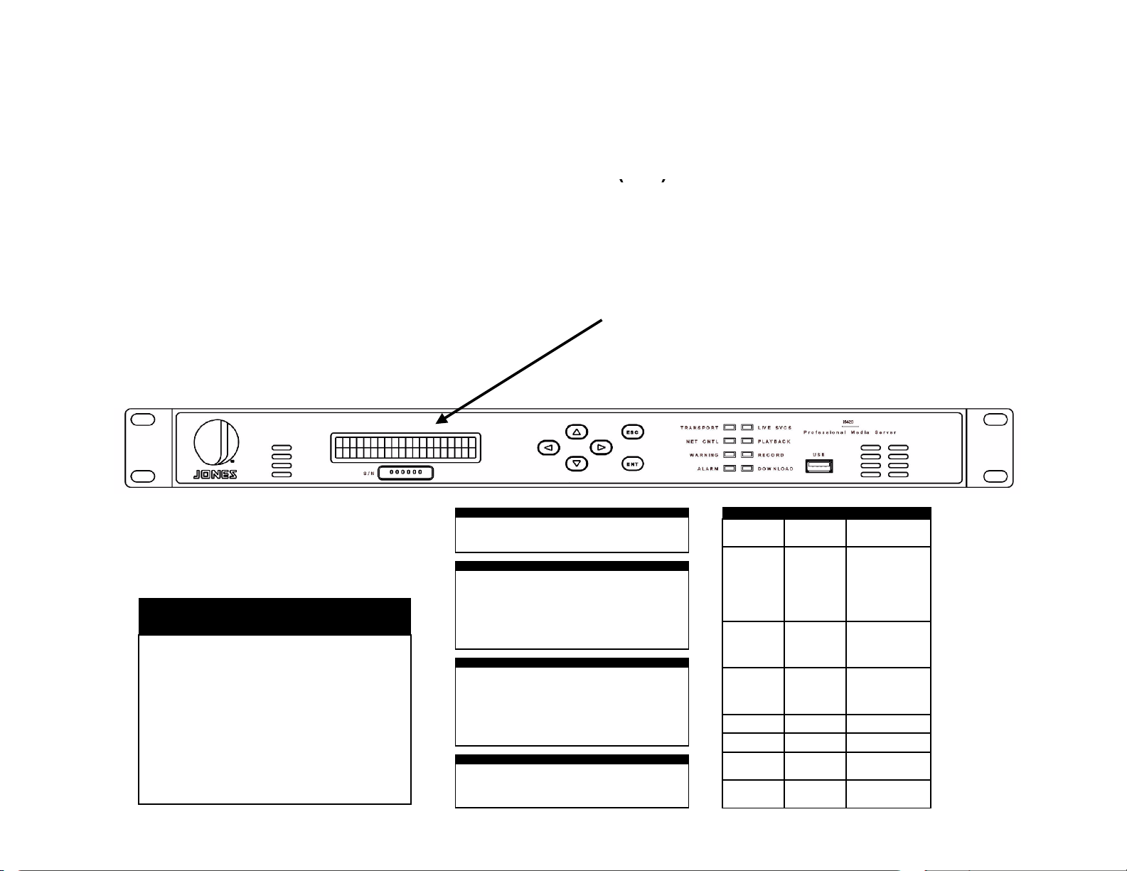
The iPump 6420 is sized at 1 RU and will fit an EIA-standard, 19-inch-wide equipment rack.
1) Install angle brackets or cross-supports capable of supporting both the unit and its connecting
cables. Screw or bolt the supports securely to the equipment rack.
2) Place the iPump 6420 on its supports and use four anchor screws or bolts and nuts to secure
the unit's front brackets to the rack.
WARNING
Do not block any of the ventilation or fan opening on the front, side, or rear of the unit. Support
arrangements that do not allow adequate air flow or that block the openings on front, side and
rear vents may result in overheating and damage to the iPump 6420.
WARNING
The front brackets must be secured to the rack. If front brackets are left unsecured, the unit may
shift forward and fall from the rack during installation or operation. Failure to secure the front
brackets may result in personal injury and/or damage to the equipment.
WARNING
Locate the iPump 6420 and its cables to avoid impacts, spills, and pulling cables and to ensure
sufficient air flow. Failure to locate the iPump 6420 in a proper environment may result in damage
to the equipment.
Table of contents
Other WestwoodOne Server manuals
Popular Server manuals by other brands

Moxa Technologies
Moxa Technologies CN2600 Series Quick installation guide

Korenix
Korenix AnyBus-X Installation leaflet

Red Hat
Red Hat DIRECTORY SERVER 7.1 SP7 - S release note

Cisco
Cisco MSE 3365 installation guide

EtroVISION
EtroVISION EV3151 installation guide

Fujitsu
Fujitsu SPARC ENTERPRISE T1000 Getting started guide

Eaton
Eaton Tripp Lite SmartPro Series Advanced user's guide

Icy Box
Icy Box IB-NAS6220 Specifications

Supermicro
Supermicro SuperStorage 2029P-DN2R24L user manual

xFusion Digital Technologies
xFusion Digital Technologies FusionServer CH242 V5 manual

HP
HP ProLiant DL60 Gen9 user guide

Valcom
Valcom VIP-9890-EM installation instructions