Wet Labs WQM Installation manual

WQM Hardware User’s Guide (wqmhw) Revision J 7 May 2009
Water Quality Monitor
(WQM)
Hardware User’s Guide
This user’s guide is an evolving document. If you find sections that are unclear, or missing
information, please let us know. Please check our website periodically for updates.
W T Labs, Inc.
PO Box 518
Philomath, OR 97370
541-929-5650
fax: 541-929-5277
www.wetlabs.com


WQM Hardware User’s Guide (wqmhw) Revision J 7 May 2009
This unit is guaranteed against defects in materials and workmanship for one year from the
original date of purchase. Warranty is void if the factory determines the unit has been abused or
neglected beyond the normal wear and tear of field deployment, or if the pressure housing has
been opened by the customer.
To return the instrument, contact W T Labs for a Return Merchandise Authorization (RMA) and
ship in the original container. W T Labs is not responsible for damage to instruments during the
return shipment to the factory. In honoring this warranty, W T Labs will supply all replacement
parts and labor, and pay for return via 3
rd
-day air shipping.
Shipping Requirements
1. Please retain the original shipping material. We design the container to meet stringent shipping
and insurance requirements, and to fully protect the WQM.
2. To avoid additional repackaging charges, return the instrument in the original ox (or other
WET La s-approved container), using the custom-cut packing foam and anti-static ag.
• If you use an alternative container, fully surround the instrument with at least 2 inches of
foam (NOT u le wrap or Styrofoam “peanuts”).
3. Clearly mark the RMA num er on the outside of your shipping container and on all packing lists.
4. Return instruments using 3
rd
-day air shipping or etter: do not ship via ground.
Attention!
Return Policy for Instruments
with Anti fouling Treatment
WET La s cannot accept instruments for servicing or repair that have een treated with anti-
fouling compounds, such as marine anti-fouling paint. These products present a handling hazard to
our technicians and can damage our la oratory equipment. You must scrape, sand, or otherwise
remove all traces of anti-fouling treatment. Also, please note that chemical strippers are likely to
damage the WQM housing.
Appendix A suggests alternate methods of iofouling prevention and removal. Please consider
using these rather than harsher anti-fouling compounds.
This return policy does not apply to the CTD’s in-line anti-fouling cartridge provided with the
instrument.


WQM Hardware User’s Guide (wqmhw) Revision J 7 May 2009 i
1. Instrument Description .................................................................................... 1
1.1 Conductivity, Temperature, Depth Sensor ...................................................................... 1
1.2 Dissolved Oxygen Sensor ............................................................................................... 1
1.3 Chlorophyll Fluorometer and Tur idity Sensor (FLNTU) ............................................. 2
1.4 BLeach Injection System (BLIS) .................................................................................... 2
1.5 Control Electronics ......................................................................................................... 2
1.6 Delivered Equipment ...................................................................................................... 3
1.7 Specifications .................................................................................................................. 4
2. Setup and Operation ........................................................................................ 5
2.1 Mounting WQM for Deployment ................................................................................... 5
2.2 Preparing the BLIS for Deployment ............................................................................... 6
3. WQM Maintenance and Cleaning .................................................................. 17
3.1 Cleaning Supplies and Solutions .................................................................................. 17
3.2 Cleaning Conductivity and Dissolved Oxygen Sensors ............................................... 18
3.3 Cleaning the FLNTU .................................................................................................... 25
3.4 Inspecting the Pressure Sensor...................................................................................... 27
3.5 Purging the BLIS .......................................................................................................... 27
3.6 Long-Term Storage ....................................................................................................... 27
4. Calibration and Characterization .................................................................. 29
4.1 Conductivity Sensor Cali ration ................................................................................... 29
4.2 Temperature Sensor Cali ration ................................................................................... 29
4.3 Pressure Sensor Cali ration .......................................................................................... 29
4.4 Dissolved Oxygen Sensor Cali ration .......................................................................... 29
4.5 Fluorometer and Tur idity Sensor ................................................................................ 30
Appendix A: Anti fouling Technical Reference ........................................................ 31
Appendix B: Internal Uninterruptible Power Supply ................................................ 31
Appendix C: Ecominder® Application ....................................................................... 32
Purpose ....................................................................................................................................... 32
Procedure ................................................................................................................................... 32


WQM Hardware User’s Guide (wqmhw) Revision J 7 May 2009 1
1. Instrument Description
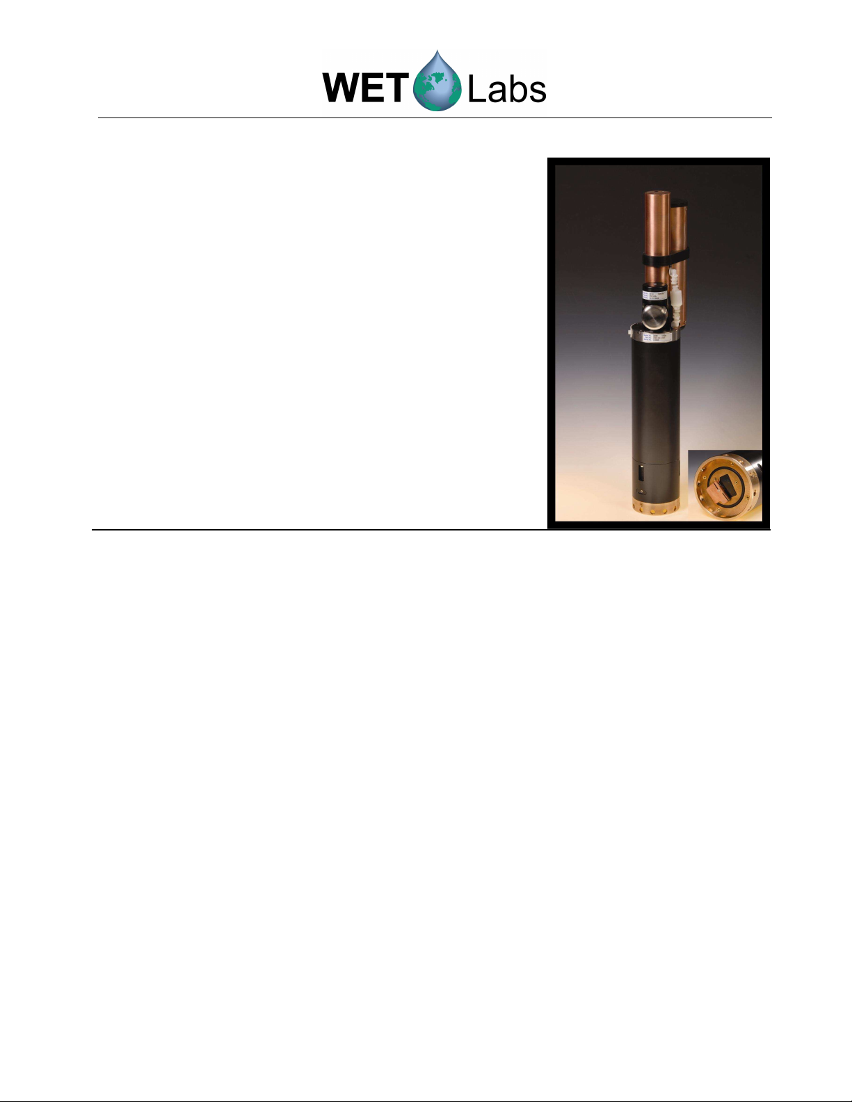
The Water Quality Monitor (WQM) is designed to
deliver core iogeochemical water quality parameters
in coastal ecosystems from a single integrated
package. The WQM com ines WET La s’
chlorophyll and fluorometer-tur idity sensors and
Sea-Bird’s conductivity, temperature, and depth
(CTD) and Dissolved Oxygen (DO) sensors.
WET La s’ WQM is designed for long-term
deployment on moorings. The WQM has undergone
extensive testing in a variety of iofouling regimes.
Please refer to the WQM page on the WET La s
we site for the most complete and updated
information, including links to live data, our latest
test results, papers, FAQ’s, and recommended
procedures.
1.1 Conductivity, Temperature, Depth Sensor
The CTD components of the WQM are the same accurate and sta le thermistor, conductivity
cell, and pressure sensors that are used in the SBE MicroCAT and ARGO float products. WET
La s has fortified them for long-term deployment on moorings in high iofouling regimes y
incorporating multiple active and passive anti- iofouling technologies. The pump-controlled,
TC-ducted system delivers a constant flow rate across the sensors; this maximizes data
coherence during sampling, and enhances the protection offered y two anti- iofouling devices
located on the inlet and outlet flow ducts. Copper canisters act as additional passive anti-fouling
protection for the CTD and the intake and exhaust of the plum ing system.
1.2 Dissolved Oxygen Sensor
The WQM incorporates a Sea-Bird Electronics SBE 43 dissolved oxygen sensor, explicitly
engineered for pumped CTD applications to provide sta le, rapid-response DO measurements.
The SBE 43 is a complete redesign of the Clark electrode sensor, incorporating numerous
features that eliminate weaknesses of previous implementations of the Clark method
(http://www.sea ird.com/technical_references/IOS43Article.pdf). These sensors undergo an 18-
point automated cali ration procedure at the factory (3 oxygen concentrations at 6
temperatures), and are well characterized with temperature, pressure and salinity in the
cali ration equations. The SBE 43 is plum ed inline with the CTD and enefits from the same
passive iofouling protection provided in the CTD. The sensor is continuously polarized using a
5-year lithium attery, eliminating long polarization wait-times of older designs.

2 WQM Hardware User’s Guide (wqmhw) Revision J 7 May 2009
Errors due to improper temperature compensation are avoided y sensor’s geometry and y
placing a thermistor near the cathode to make the temperature compensation measurement in
phase with the oxygen measurement. The pump produces a fixed flow rate across the
mem rane, ensuring adequate flow past the sensor and eliminating changing response time with
variations in flow. The result is sensor with a response time of less than 2 seconds.
Periodic injection of leach, a rapidly diffusive oxidizer, immediately inhi its iota present
within the pumped volume and compliments the slowly diffusing road spectrum anti-foulant
cartridges protecting the conductivity cell. The leach is especially helpful when the sampling
interval is less than 30 minutes. Sampling more often may not allow the slowly diffusing anti-
foulant to uild to its most effective concentration. The multi-tiered anti-foulant approach
allows users to make a knowing choice etween short sample intervals and fouling resistance to
suit their science and operational goals.
1.3 Chlorophyll Fluorometer and Turbidity Sensor (FLNTU)
The com ination fluorometer and tur idity sensor uses a dual-LED/single-detector system that
measures oth chlorophyll fluorescence and tur idity within the same volume of water.
Chlorophyll fluorescence is excited with a 470 nm LED, while the tur idity measurement
employs a 700 nm LED. The detector measures the returned light using a filter set to limit the
response to the near infrared region corresponding to the peak of chlorophyll emission (695 nm)
and the particulate ackscattering at 700 nm. The detector angle, with respect to the excitation
optics, is 140 degrees.
1.4 BLeach Injection System (BLIS)
Each WQM is equipped with a leach injection system. The system periodically injects user-
determined measured amounts of a household-grade leach solution into the plenum of the DO
sensor. Field trials show that periodic leach injection prolongs the WQM deployment y at
least a month or more.
1.5 Control Electronics
The control electronics and associated firmware and software allow the user to program the
WQM sampling scheme, output, and leach injection routine. For specific information a out
software controls, please see the WQM software user’s guide.

WQM Hardware User’s Guide (wqmhw) Revision J 7 May 2009 3
1.6 Delivered Equipment
Installed Parts
Qty Item P/N
1
1
6-socket dummy plug
Lock collar
EXA-KX0038
EXA-KX0025
1
1
4-pin dummy plug
Lock collar
EXA-KX0004
EXA-KX0025
Spare Parts Kit
Qty Item P/N
1
Playtex® Premium Nurser kit (silicone nipple); includes drop-in liners
XXX-000086
XXX-000087
1
Test ca le
CXA-KX0115
1
1
Pigtail, six-socket
Lock collar
EXA-KX0018
EXA-KX0025
1
3/32-in. hex key for Bio-wiper™
GXA-SX0050
1
5/32-in. hex key for CT–BLIS clamp
GXA-SX0109
1
7/64-in. hex key for BLIS
GXA-SX0093
3
4-40 x 3/8-in. 316 stainless steel socket-head cap screws for Bio-wiper™
GXA-SX0099
8
4-40 x ¼-in. pan head acetal flathead screws
GXA-SX0146
3
4-40 x ¼-in. flat head Phillips screws
GXA-SX0155
4
6-32 x 3/8-in. nylon socket-head cap screws for BLIS
GXA-SX0067
1
Fluorescent stick for ench testing FLNTU
MAA-220050
1
Scotch-Brite™ pad for cleaning copper
XXX-000229
1
CT-DO cleaning device
50431
1
50 ml plastic ottle, Triton
®
X-100
50091
1 Ecominder anti-fouling paint kit BAA-003000
1 3/8-in. right-angle hose ar RXA-031630

4 WQM Hardware User’s Guide (wqmhw) Revision J 7 May 2009
1.7 Specifications
Conductivity
Temperature
Range
0–9 S/m
Range -5–35 deg C
Accuracy 0.003 mS/cm
Accuracy 0.002 deg C
Resolution 0.0005 S/m
Resolution 0.001 deg C
Depth
Dissolved Oxygen
Range 0–100 or –200 m
Range
a
120%
Accuracy 0.1% FS
Accuracy
b
0.1 mg/l
Resolution 0.01% FS Resolution 0.01 mg/l
Fluorescence
Turbidity
Range
c
0–50 µg/l
Range
c
0–25 NTU
Accuracy
d
0.2% FS µg/l
Accuracy 0.1 FS NTU
Precision 0.04% FS µg/l
Precision 0.04% FS NTU
Wavelength X/ M 470/695 nm
Wavelength 700 nm
Electrical
Mechanical
Connector MCBH-6-MP, MCBH-4-FS
Depth
e
200 m
Output RS-232
Pressure housing Acetal copolymer, ABS, PVC,
titanium, copper
Input 12–18 VDC
Current draw 275 mA (typical) Dimensions 65.4 cm long x 18.5 cm max OD
Current draw < 100 µA (sleep)
Weight in air 5.4 kg
Sample rate 1 Hz
Weight in water 1.8 kg
a. Oxygen range is relative to surface saturation.
b. +/- 0.2 mg/l or 2% of reading, whichever is greater.
c. Available measurement ranges:
• 0–30 µg Chl/l, 0–10 NTU
• 0–50 µg Chl/l, 0–25 NTU
• 0–125 µg Chl/l, 0–1000 NTU
d. Chlorophyll fluorescence is created by living organisms and is subject to taxonomical and physiological
changes. Field calibration is highly recommended. See user’s guide for standard protocols.
e. Depth rating is the lesser of 200 m or the pressure sensor rating.
1.7.1 Connector Pinout Summary for WQM
Pin
Function
1
Ground
2
RS-232 (RX from host)
3
NC
4
V +
5
RS-232 (TX to host)
6
NC
Socket
Function
--
NC
--
NC
--
NC
-- NC

WQM Hardware User’s Guide (wqmhw) Revision J 7 May 2009 5
2. Setup and Operation
The illustrations elow show the main exterior features and sensor locations of the WQM, in its
vertical orientation: the CTD is at the top and the fluorometer and tur idity optical sensors are at
the ottom, facing down. This allows u les to float free of the CT- and DO-sensors’ plum ing
system, and it shields the optical sensors from direct sunlight. Under normal conditions, the optical
sensors are not sensitive to external light sources; however, the detector may saturate if pointed
directly at the sun.
2.1 Mounting WQM for Deployment
WET La s recommends an vertical, or upright, mounting orientation.
The est location for mounting clamps (availa le
separately from WET La s) is along the 20.9-cm
long surface of the ody. See illustration at right. Do
not attach clamps elow the connector, or to the
copper parts on top. The ca le will loop down elow
the connector. To keep it from interfering with the
optical instruments, attach it to the guard ring with a
ca le tie.

6 WQM Hardware User’s Guide (wqmhw) Revision J 7 May 2009
2.1.1 Mounting WQM for Horizontal Deployment
When it is not possi le to orient the WQM vertically, it may e mounted horizontally, as
shown elow. Note that the intake duct is in the 9:00 position when viewed from the end of
the CTD (see left image elow). Horizontal mounting creates a challenge for the pump and
plum ing to purge air from the system. The orientation shown helps the pump fill with
water, ena ling it to operate properly. Several sample cycles may pass efore all u les
are purged from the system. If noisy conductivity data persists when operating the
instrument horizontally, a special plum ing fitting is availa le to improve air purging.
Contact WET La s. Place mounting clamps (optional equipment) on the main ody of the
WQM, as for vertical mounting. (See illustration on page 5.)
2.2 Preparing the BLIS for Deployment
During normal operations, to prevent leach from eing pumped into a dry CT-DO sensor
manifold, the BLIS operates only when the WQM is immersed in water.
WARNING!
Bleach is very corrosive and harmful to almost every part of the WQM. Great care
should be taken to ensure that bleach is not inadvertently pumped by the BLIS into
the WQM. When testing the BLIS system, the WQM should always be immersed in
water and the plumbing filled with water.
Before a WQM is deployed, the BLIS must e filled with leach and the BLIS pump primed.
BLIS uses a 125 ml Playtex
®
Premium Nurser a y ottle as a leach reservoir. This product
has a disposa le drop-in liner of HDPE plastic, and a silicone nipple, which allow long-term
exposure to leach. DO NOT su stitute other ottles.
The host software calculates the maximum deployment time ased on each pump’s cali ration
information. The software also allows you to adjust the injection quantity and frequency. The
rate of marine growth in your area may e an overriding factor in setting your leach injection
schedule. Other factors to consider are leach quality, age, and concentration.
The BLIS pump’s injection rate may vary as it ages. WET La s will test the pump and adjust
the cali ration during annual servicing.

WQM Hardware User’s Guide (wqmhw) Revision J 7 May 2009 7
2.2.1 Check LIS Operation
1. Remove the BLIS end cap: Use a 7/64-in.
hex key to remove the two screws.
2. Twist and pull to remove the cap and expose
the leach reservoir.

8 WQM Hardware User’s Guide (wqmhw) Revision J 7 May 2009
3. Grasp the leach reservoir y the rim of the
ottle and pull gently. You may feel the
resistance of a slight suction as the nipple
pulls free of the intake.
4. Remove the BLIS–CTD clamp. Use a 5/32-in.
hex key to loosen the clamp. Slide it up and off
the BLIS and CTD.
5. Use a 7/64-in. hex key to remove the two
screws at the ase of the outer BLIS sleeve
(copper tu e).

WQM Hardware User’s Guide (wqmhw) Revision J 7 May 2009 9
WARNING!
The BLIS will clog and malfunction if it intakes sediment or other solids.
6. Remove the outer BLIS sleeve y
pulling straight up with a minimum
of twisting.
WARNING!
Do not scrape the sides of intake. Scratches on this surface will prevent the
nipple of the bleach reservoir from sealing properly.
7. Clean the BLIS module ( lack plastic housing
attached to WQM) with fresh water and a rag
to remove all sediment and loose material.
Inspect the intake and rinse it gently with fresh
water if you see de ris in the intake.

10 WQM Hardware User’s Guide (wqmhw) Revision J 7 May 2009
8. Clean the BLIS cap and outer sleeve with fresh
water and a rag to remove all sediment and
loose material. These parts must e clean to
protect the BLIS intake during reassem ly.
Firmly attached corrosion (i.e. patina) is ok.
Flaking corrosion must e removed with
Scotch-Brite.
9. Connect the WQM to the host PC and esta lish
communication with the host software. Supply
power to the WQM: it will automatically egin
collecting data. Select Stop WQM Sample.
Fill the leach intake port with water. Command the pump to inject 300 squirts (150
seconds at 2 Hz). The intake should e emptied efore the pump stops.
Trou leshooting water in the intake—if the water level does not recede:
• Make sure you’re giving it enough time. The flow rate is ~1ml/min.
• Can you hear the pump clicking? It makes a “squishy” clicking sound that is distinct from the
sharper clicking that occurs simultaneously inside the WQM closer to the ECO.
• If the pump is not clicking, make sure the unit is plugged in and powered up. Check
communications via the host.
• Check again for intake lockage.
• Call WET La s Technical Support for further instructions or to o tain an RMA for return.
10. Reassem le the outer sleeve to the ase of the
BLIS. The slot in the sleeve must line up with
the little tu e etween the BLIS and the CT-DO
sensor head.

WQM Hardware User’s Guide (wqmhw) Revision J 7 May 2009 11
11. Secure the outer sleeve to the BLIS ase.
Install the two 6-32 x 3/8-in. screws using
the 7/64-in. hex key.
12. Slide the clamp over the CT guard and the BLIS
sleeve into position, approximately as shown.
Use the 5/32” hex key to snug up the screw. Do
not overtighten.
13. Install the BLIS end cap:
Unless you are returning the WQM to service
immediately, install the BLIS end cap to keep the
parts together and to keep the BLIS intake clean.

12 WQM Hardware User’s Guide (wqmhw) Revision J 7 May 2009
2.2.1 Fill the LIS Reservoir with leach
1. BLIS reservoir parts (L-R): ottle ody, drop-
in liner, silicone nipple with threaded cap.
2. Install the drop-in liner in the ottle ody. Push
the liner’s ottom with your fingers to give it
some shape.
3. Use a graduated cylinder to measure leach;
record the amount used. The reservoir holds
125 ml nominal, or 150 ml to the rim.
4. Pour the leach into the liner. Note that dye
was added for these photos.
5. Screw on the cap and silicone
nipple. Make it snug, ut do not
overtighten. The nipple will fill
with solution when mounted in
the vertical (recommended)
orientation.
6. If you intend to mount the WQM horizontally, or if
the air in the reservoir is otherwise of concern, purge
the air y pushing up on ottom of the drop-in liner
with your fingers until leach flows from the nipple.

WQM Hardware User’s Guide (wqmhw) Revision J 7 May 2009 13
2.2.2 Install LIS Reservoir
1. Wet reservoir’s nipple with clean water, then set it into the
BLIS as shown.
2. Seat the nipple in the intake. Grasp the rim of the
reservoir and rotate the reservoir ack and forth
a out 15 degrees (a out 1 cm at the rim.)
Gently push down on the rim as you rotate it and
the nipple will seat properly in the intake.
If you have any question a out performing this
procedure, practice while the BLIS outer sleeve is
removed. Use water, not leach when practicing.

14 WQM Hardware User’s Guide (wqmhw) Revision J 7 May 2009
3. Set the BLIS end cap into the BLIS outer
sleeve. It will compress the reservoir and
ensure that the nipple remains sealed in
the intake.
WARNING!
Bleach is corrosive to many of the WQM’s outer components. Avoid spilling
bleach onto the instrument.
4. Gently press down on the cap and align the
threaded holes in the cap with the holes in the
outer sleeve.
Other manuals for WQM
1
Table of contents