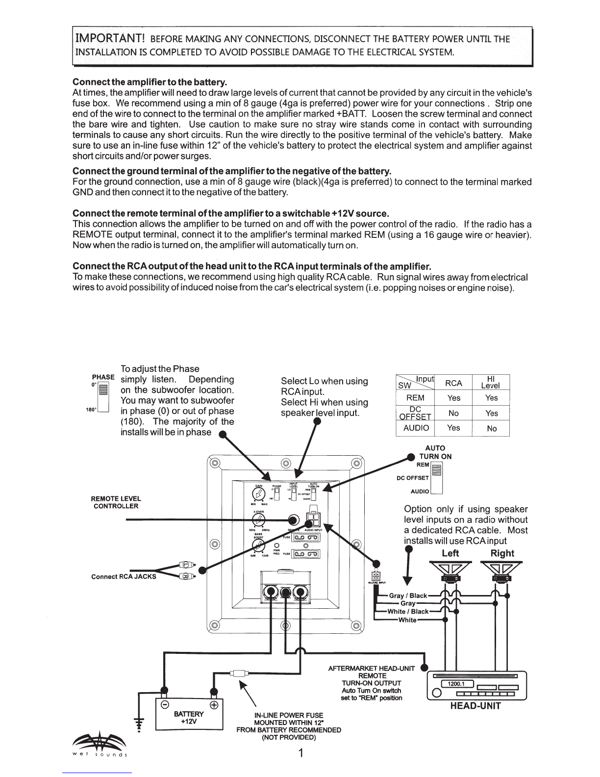
AuTo
TURN
ON
SwiTCH
The "REM"setting is the best
way
toturn the uniton and offbutifyou
do
nothavea
REMOTE
outputwirefrom your
head-unit then you will need to use eitherthe "AUDIO"
or
"DC OFFSET" setting.
Not
all head-units are the same
this is
why
we
provide threedifferentTurn On options. You will need to selectthe setting thatworks bestwith your
head-unit.
(The
AUDIO
& DC
OFFSET
setting areto be used with the Hi-level connections below.
AUTO
J
The"REM" setting is used when
your
head-unithas a
+12V
outputwire.
R!~R~N
° The "DC OFFSET"setting sensesthe voltage change when the head-unitis turned on and off
oc
oFFSET
II
_and
does notdepend on musicasthe
AUDIO
setting above.
Must
use
Hi-level
input
for
this
setting.
AUDIO
L
The "AUDIO" setting senses the music signal to turn on the amplifier. This setting will work
with anyhead-unit.
In
this setting the amplifierwill onlyturn on when itsenses music, so even
if
your
head-unit is on but at"0" volume the amplifierwill not turn on. Must use
RCA
input for
this setting.
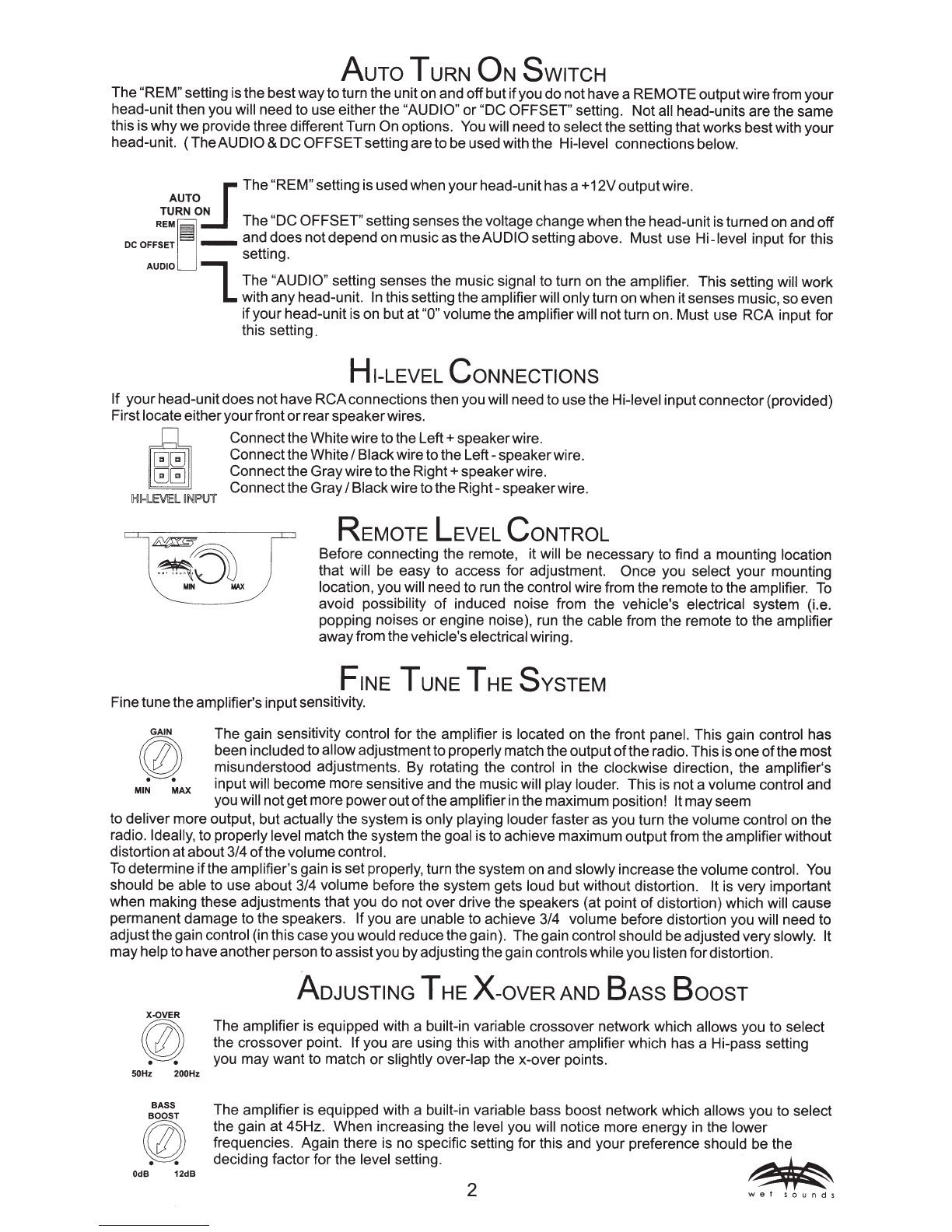
HI-LEVEL
CoNNECTIONS
If
your
head-unitdoes nothave
RCA
connectionsthen you will need to usethe Hi-level inputconnector(provided)
Firstlocate
eitheryourfront
or
rear
speaker
wires.
IHH-liEVEl
~INJPUT
Connectthe Whitewiretothe
Left+
speakerwire.
ConnecttheWhite
I
Blackwireto
the
Left-
speakerwire.
Connectthe
Gray
wiretothe
Right+
speakerwire.
Connectthe
Gray
I
Blackwire tothe
Right-
speaker
wire.
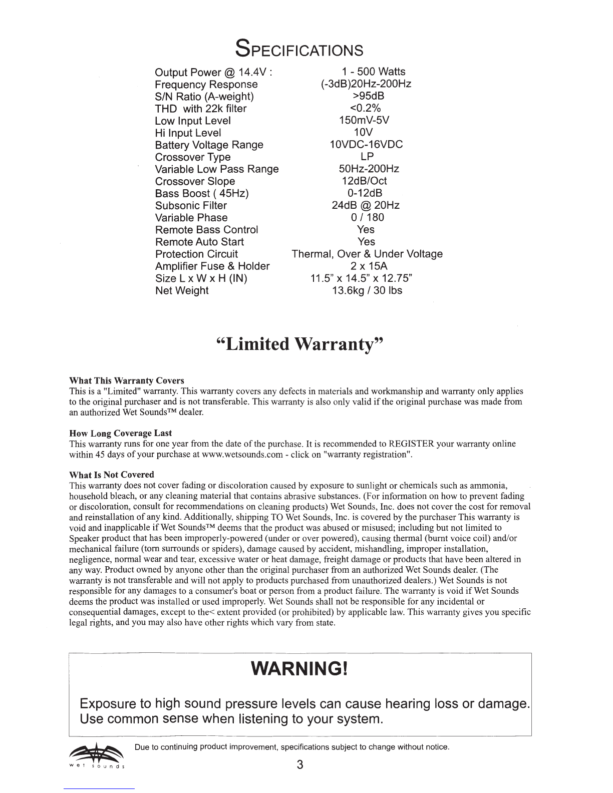
lSJ
MIN
MAX
REMOTE
LEVEL
CoNTROL
Before connecting the remote, it will be necessary to find a mounting location
that will be
easy
to access for adjustment.
Once
you select
your
mounting
location, you will need to run the control wire from the remote tothe amplifier.
To
avoid possibility
of
induced noise from the vehicle's electrical system (i.e.
popping noises
or
engine noise), run the cable from the remote to the amplifier
away
from the vehicle's electrical wiring.
FINE
TUNE
THE
SYSTEM
Finetunethe amplifier's inputsensitivity.
GAIN
The gain sensitivity control for the amplifier is located on the front panel. This gain control has
rnrzr
been includedtoallowadjustmentto properlymatchthe output
of
the radio. This is one
of
themost
~
misunderstood adjustments. By rotating the control in the clockwise direction, the amplifier's
Ml~
~AX
inputwill become more sensitive and the musicwill play louder. This is not a volume control and
you will notgetmore
power
out
of
theamplifierin the maximum position! Itmayseem
to deliver more output, but actually the system is only playing louderfaster as you turn the volume control on the
radio. Ideally, to properly level match the system the goal isto achieve maximum outputfrom the amplifierwithout
distortion atabout
314
of
the
volumecontrol.
To
determine ifthe amplifier's gain is set properly, turn the system on and slowlyincreasethe volume control. You
should be able to use about
314
volume before the system gets loud but without distortion. It is very important
when making these adjustments that you
do
not
over
drive the speakers (at point
of
distortion) which will cause
permanent
damage
to the speakers. Ifyou are unable to achieve
314
volume before distortion you will need to
adjustthe gain control (in this case you would reduce the gain). The gain control should be adjusted veryslowly. It
may
helpto haveanotherperson to assistyou
by
adjusting the gain controlswhile you listen fordistortion.
0
. .
50Hz 200Hz
BASS
0
. .
OdB
12dB
ADJUSTING
THE
X-OVER
AND
BAss
BoosT
The amplifier is equipped with a built-in variable crossover network which allows you to select
the crossover point. If you are using this with another amplifier which has a Hi-pass setting
you
may
want
to match
or
slightly over-lap the x-over points.
The
amplifier is equipped with a built-in variable bass boost network which allows you to select
the gain
at
45Hz.
When
increasing the level you will notice more energy in the
lower
frequencies. Again there is no specific setting for this and
your
preference should be the
deciding factor
for
the
level setting.
~
2
wet
sounds