WFCO WF-68100 Series User manual

Operator’s Manual
Distributed in the U.S.A. and Canada by
ARTERRA DISTRIBUTION
(877) 294-8997
Warranty: [email protected]
Fax (574) 294-8698
www.wfcoelectronics.com Power PROs Technical Support
(877) 294-8997
WF-9900 Series
Deckmount Converter-Charger
WF-68100 Series

SAFETY INFORMATION ........................................................................................................... 3
GENERAL INFORMATION
Reverse Battery Protection ........................................................................................................... 3
Automatic Cooling Fan ................................................................................................................ 4
Over-Temperature Protection ...................................................................................................... 4
Electronic Current Limiting ......................................................................................................... 4
Short Circuit Protection ............................................................................................................... 4
CIRCUIT PROTECTION
DC Fuses ......................................................................................................................................... 5
OPERATIONAL FEATURES
ree Stage Smart Charging ........................................................................................................ 6
Front Panel Features ...................................................................................................................... 6
TROUBLESHOOTING INSTRUCTIONS
Converter Output Voltage ............................................................................................................. 8
Reverse Polarity Fuses ................................................................................................................... 8
Battery Select Switch ...................................................................................................................... 9
Troubleshooting Flow Chart ......................................................................................................... 9
GENERAL COMPLIANCE INFORMATION
Agency Listings ............................................................................................................................... 9
INSTALLATION INSTRUCTIONS
Mounting the Enclosure ...............................................................................................................10
DC Connections ............................................................................................................................10
AC Connections ............................................................................................................................11
SPECIFICATIONS .......................................................................................................................... 12
WARRANTY INFORMATION ....................................................................................................13
TABLE OF CONTENTS
2

3
GENERAL INFORMATION
WF-68100 Series Converter-Charger Safety Features
Reverse Battery Protection
e WF-68100 Series Converter-Chargers will charge the 12-volt house battery if installed. A
battery does not have to be installed for WF-68100 Series Converter-Chargers operation. When
a battery is installed, three reverse polarity fuses are installed to protect the converter circuitry.
e fuses are located on the rear panel of the enclosure near the AC power cord (refer to Figure
1 below). is feature prevents permanent damage to the converter from a battery connected
into the circuit backwards. In addition to protecting the converter-charger, the reverse polarity
fuses are the main connection between the converter-charger and the DC fuse board of a
distribution center.

Automatic Cooling Fan
e cooling fan in the WF-68100 Series Converter-Chargers is 2-stage and is controlled by
the current drawn out of the converter to the applied load. e on-board microprocessor
increases fan speed as the total load increases and decreases fan speed as the load
decreases.
Unlike traditional temperature-controlled fans, the load-controlled fan provides better
component cooling by avoiding temperature spikes which can lead to premature component
failure.
Over-Temperature Protection
If the internal temperature of the converter exceeds a critical point, it will shut down. is
protects the unit from excessive heat that may damage sensitive components. e unit will
restart once the temperature inside has dropped.
Electronic Current Limiting
In the event that the output current exceeds the maximum rating for the WF-68100 Series
Converter-Charger, the output current will remain constant, but the output voltage will
begin to drop. If this occurs, the unit will recover once loads are reduced.
Short-Circuit Protection
Should a short circuit occur in the RV, the WF-68100 Series Converter-Charger will drop
the voltage output to zero volts. If the short-circuit condition is removed and no other
fault conditions are detected, the converter will resume normal operation. However, short-
circuit conditions are dangerous, and an RV will require inspection by a qualied service
technician.
4
Figure 1

5
CIRCUIT PROTECTION
WF-68100 Series Converter-Charger Fuses
DC Fuses (12 Volts)
e DC fuse receptacle on the rear panel of the WF-68100 Series Converter-Charger has space
for 3 (three) identical Reverse Battery Protection fuses (see Figure 1 above). ese fuses should
be replaced with ATC or ATO automotive type fuses, such as Littelfuse type 257 or Bussmann
type ATC. e fuses are 35 Amp.
OPERATIONAL FEATURES
Converter Operation Modes
ree-Stage Smart Charging
e three-stage “smart” charger continuously measures the battery voltage output and regulates
the amount of charge using three modes of operation; Absorption, Bulk, and Float.
3-Stage Charging
WFCO converters of every style have become the favored brand for power conversion and
electric distribution in the RV industry. ey provide RV owners an ecient and cost-eective
method to use an AC power source and provide power to DC components inside the RV, while
charging accessory batteries at the same time.
Smart Engineering: ree Stage Charging is Better
WFCO’s automatic three-stage converters handle every charging need for the RV while extending
the battery’s life. Well-maintained batteries should never need more than two-stage (Normal and
Trickle) charging. Our third stage (Bulk) is provided for the rare times a battery needs extra power
for charging. RVs are frequently sold with at least one 12 VDC accessory battery installed. is
battery is normally a deep-cycle battery that has the ability to sustain a slower drain of power. RV
owners nd this useful when powering loads such as lights, radios, and refrigerators without being
connected to AC power or running the motorhome engine. As soon as the RV is connected to AC
power, the converter begins charging the battery as needed, while, at the same time, providing 12
VDC power to loads such as lights, radios, and refrigerators.
When the RV is connected to AC power, users frequently use the lights, refrigerators, fans, and
other electronics as they would in their home. RV users also expect the battery to be fully charged
when they want to disconnect from power and move the RV, or when they are dry camping and
turn o their generator.

6
Absorption Mode:
is is the default, or normal operation, providing an output of 13.6 volts DC. Because
RVs today are designed with converters sized to provide ample DC output power for all
DC loads in normal usage, an RV will rarely require anything other than Absorption
Mode.
When a WFCO converter is connected to a battery in Absorption Mode, power is
available for charging that battery whenever the converter output is greater than the
voltage level of the battery. If the battery is at or near fully charged, the current draw from
the converter to the battery may be very small. On the other hand, if the battery were to be
fully discharged, the current draw from the converter to the battery may be quite high.
Testing has shown that a completely discharged battery (11.9 VDC) connected to a WFCO
converter in Absorption Mode with an output of 13.6 VDC and having a 20 Amp lighting
load connected to the converter will charge the battery to its fully charged level of 12.7
VDC in fewer than three hours. Adding more DC loads will lessen the amount of current
available and will lengthen the time required to charge the battery. Batteries with damaged
cells will also require additional time to charge and may never reach a full charge voltage.
Because of the relationship between voltage and amperage, once the converter reaches its
maximum rated operating current level, any increase in the DC load will start to decrease
the voltage output level. When the output from the converter reaches a preset level, the
converter will go into Bulk Mode.
Bulk Mode:
is is designed to charge a signicantly discharged battery in a little less time than
Absorption Mode. e microprocessor in WFCO converters continuously monitors the
DC line voltage. When the microprocessor detects the preset voltage level, it will boost the
converter voltage to 14.4 VDC. e increased voltage will help the battery charge faster,
while still providing power to the DC appliances in the RV.
Figure 2

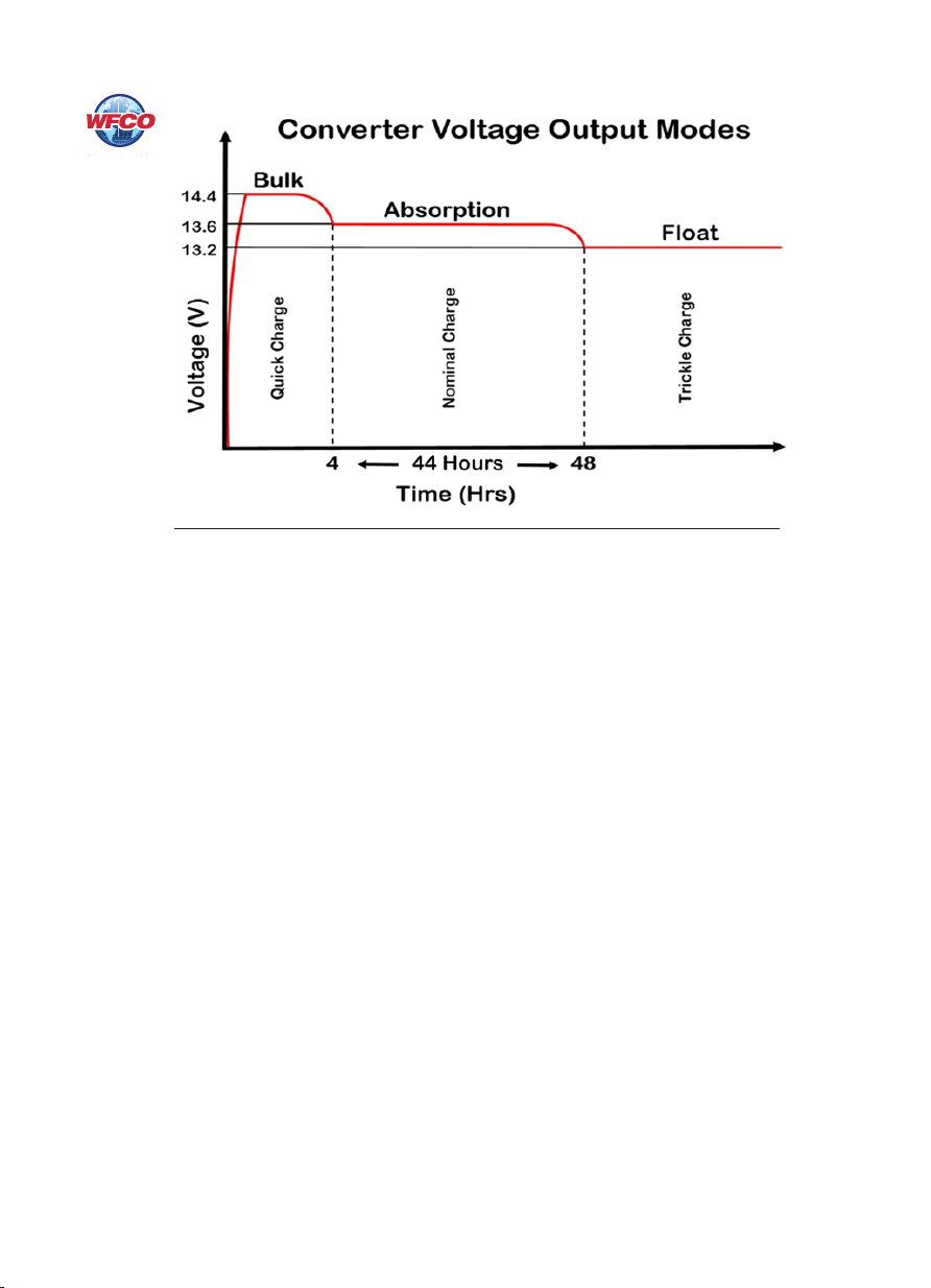
In Bulk Mode, it may not be possible to observe the 14.4 VDC output because of the
voltage-current relationship. To measure the 14.4 VDC, reduce some DC loads while
monitoring the voltage at the converter output. As the DC loads are removed, the voltage
will begin to climb until 14.4 VDC (nominal) is shown on the meter.
As the battery continues to charge, the current drawn by the battery will gradually decrease.
WFCO converters are designed to drop out of Bulk Mode when the total amperage draw
from the converter reaches a preset point, indicating the battery is charged. If the amperage
draw stays above the preset point, the converter will stay in Bulk Mode for a maximum
of four hours. ese features have been implemented to protect and extend the life of the
batter y.
Float Mode:
is is the third stage of converter operation. is mode is designed to provide a trickle
charge to the battery. If the converter observes no signicant variations in current draw for
approximately 44 continuous hours, it will drop the output of the converter from 13.6 VDC
to 13.2 VDC. is lower voltage will keep the battery charged while the RV is not in use.
is also helps preserve the life of the battery, while keeping it charged and ready for use. A
change in DC current will cause the converter to exit Float Mode and return to the default,
or normal, Absorption Mode.
Note: e converter, while in Float Mode, will continue to supply a trickle charge to the
battery. If the RV is in storage for thirty (30) days or more, be sure to check the battery and
its uid levels.
Front Panel Features:
ree front panel LEDs show the converter’s operating status at a glance:
• Green LED – Normal operation, connected to 110 VAC.
• Amber LED – Steady ON: the battery is discharging when operating on battery only.
Flickering: the battery is approaching a low level
• Red LED – A fault has been determined in one of the protection circuits: Overload,
Over-Temperature or Short-Circuit. e LED does not light if a battery Reverse Polarity
occurs.
A Manual Override switch is provided to force the converter into Bulk Mode to quick
charge the batteries if necessary. NOTE: Placing the converter into Bulk Mode with a fully
charged battery could overcharge the battery.
7
Figure 3

TROUBLESHOOTING INSTRUCTIONS
Troubleshooting the WF-68100 Series Converter-Charger
Converter Output Voltage
Before checking the WF-68100 Series Converter-Charger output voltage, disconnect the
battery cables at the battery. Make sure the converter is plugged into an AC source (105-
130 Volts). Check the converter output voltage at the battery with a voltmeter. Place the
meter probes on the disconnected battery cables; place the Positive (red) meter probe on
the + Positive red battery wire and place the Negative (black) meter probe on the
-Negative black wire on the battery cable (Figure 4). Be sure you have good connections
at the cables. If the voltage reads 13.6 - 14.4 VDC (+/- 0.2) with no load, the converter is
functioning properly.
If the converter output voltage at the battery reads 0.0 VDC, or if the battery is not
charging, check for an open inline fuse in the battery wire circuit. One may have been
installed by the RV manufacturer. Also check for loose wiring connections.
Reverse Polarity Fuses
If there is no DC output coming from the WF-68100 Series Converter-Charger output
lugs, rst check the reverse polarity fuses on the rear panel. en, visually inspect the
fuses for any breaks in the fuse element. If no breaks are found, use a continuity tester to
check for continuity. If the reverse polarity fuses are blown, it means the RV battery was
accidentally connected in reverse, either at the battery or at the converter. Investigate the
connections and reconnect the cables properly. Replace the fuse with the same type and
amperage rating as the original.
IMPORTANT: ese fuses protect the converter from damage if the RV battery is
accidentally connected in reverse. A reversed battery connection, even if for only a
second, will cause these fuses to blow.
8
Figure 4

Battery Select Switch
e Battery Select switch is a 2-position slide switch that selects either Lead Acid/AGM or
Gel battery. In the Lead Acid/AGM position, the converter will output both Absorption
and Bulk Mode voltages.
With the Battery Select switch in the GEL position, the output will remain in Absorption
Mode. Bulk Mode is disabled to prevent damage to the GEL batteries.
If the above checks have been made but the converter output still reads 0.0 VDC, the
converter is not functioning properly.
9
Figure 5
GENERAL COMPLIANCE INFORMATION
Agency Listings
UL
e WF-68100 Series Converter-Chargers are UL-Listed, and cUL-Listed (Canadian).
FCC Compliance Class B
NOTE: is equipment has been tested and found to comply with the limits for a Class B
digital device, pursuant to Part 15 of the FCC Rules. ese limits are designed to
provide reasonable protection against harmful interference when the equipment is
operated in a commercial environment. is equipment generates, uses, and can
radiate radio frequency energy, and if not installed and used in accordance with the
instruction manual, may cause harmful interference to radio communications. Operation
of this equipment in a residential area is likely to cause harmful interference in which case
the user will be required to correct the interference at his own expense.

10
INSTALLATION INSTRUCTIONS
Installing the WF-68100 Series Converter-Charger
Mounting the Enclosure
e WF-68100 Series Converter-Charger enclosure should be mounted in an accessible area
such as a wall or in the side of a cabinet. Select a mounting location near the shore power and
battery (batteries), in an area where the owner is unlikely to store items as this could reduce
clearance requirements, obstruct ventilation openings and aect the performance of the
converter. e location should be selected to prevent excessive heat, water, moisture, dust and
dirt entering the unit installed. As a rule, allow a minimum of two cubic feet of clear airspace
and or any additional venting as necessary to prevent the unit from overheating. e front of the
enclosure should not be obstructed to allow free air ow for the cooling fan (Figure 6).
An 8AWG copper conductor shall be used to bond the WF-68100 Series Converter-Charger to
the vehicle frame.
DC Connections
Connect a Red 2 AWG wire to the POS+ lug on the distribution center’s fuse board. Make sure
this lug is torqued properly. In a similar fashion, connect a Black 2 AWG wire to the NEG- lug on
the distribution center’s fuse board.
Figure 6

11
AC Connections
e WF-68100 Series Converter-Chargers receive power from the power cord located to the le
of the rear panel fan. Due to the higher current required from the AC line to produce the high
DC current output, a 20 Amp power plug is provided.
e 20 Amp plug and corresponding receptacle are shown in Figure 7 below. e 20 Amp
receptacle must be wired back to the fuse box using 12AWG wire minimum.
Figure 7

12
Figure 8

13
CONSUMER LIMITED WARRANTY
for WFCO Electronic Products
WFCO extends, to the original owner, a Two Year Limited Product Warranty. is
warranty is in eect from the date of original purchase for a period of two (2) years. is
limited warranty is extended specically for and is limited to Recreational Vehicle
application and is
only valid within the continental United States, Alaska, Hawaii and the
Provinces of Canada.
WFCO warrants, to the owner, that its products are free from defects
in material and workmanship under normal use and service based on its intended use and
function. is warranty is limited to the repair or replacement, at WFCO’s discretion, of any
defective parts or defective assembly. Any implied warranties of merchantability or tness
for intended use are limited in duration unless applicable State Law provides otherwise. You
may have other rights as specied by each individual state.
EXCLUSIONS and LIMITATIONS
e OEM warranty specically does not apply to the following:
• Any WFCO product that has been repaired or altered by an unauthorized person;
• Any damage caused by misuse, faulty installation, testing, negligence, accident or any
WFCO product installed in a commercial vehicle;
• Any WFCO product, whose serial number has been defaced, altered or removed;
• Any WFCO product, whose installation has not been in accordance to the WFCO
written instructions;
• Any consequential damages arising from the loss of use of the product including but not
limited to: inconvenience, loss of service, loss of revenue, loss or damage to personal
property, cost of all services performed in removing or replacing the WFCO product.
Specications are subject to change without notice or obligation.
• Any WFCO Electronics products sold through unauthorized Internet sources
(Example: eBay) will be excluded from all warranty coverage oered by Arterra
Distribution / WFCO.
CONSUMER WARRANTY CLAIM PROCEDURE
Upon determination and validation by an authorized OEM dealer that a WFCO product has a
defect, a Return Goods Authorization (RGA) number will be required before the product can
be returned. e RGA number can be requested by completing the Warranty Information Fax
Sheet and appropriate Troubleshooting Form found at www.wfcoelectronics.com. Once these
forms have been completed, email the forms along with Proof of Purchase to
warranty@wfcoelectronics.com or fax the three documents to the Warranty Department at
(574) 294-8698. Aer receipt of the forms, an RGA number will be issued. is number shall
appear on all correspondence with warranty service. Upon validation of the warranty, WFCO
shall replace the product with a like product. e RGA number shall be placed on the outside
of the carton used to return the product for ease of identication. Do not mark directly on
the product. e product must be packaged properly to avoid further product damage which
could cause a non-warrantable condition.
WARRANTY ASSISTANCE
e consumer may contact the selling Dealer or OEM for warranty assistance.
e consumer may also contact Arterra Distribution, exclusive distributor to WFCO
Products at: (574) 294-8997 or Fax (574) 294-8698.

14

15

WFCOELECTRONICS.COM
Other manuals for WF-68100 Series
2
Table of contents
Other WFCO Batteries Charger manuals