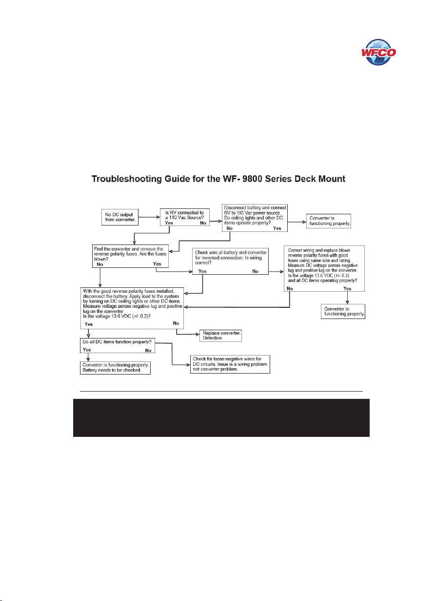
5
CIRCUIT PROTECTION
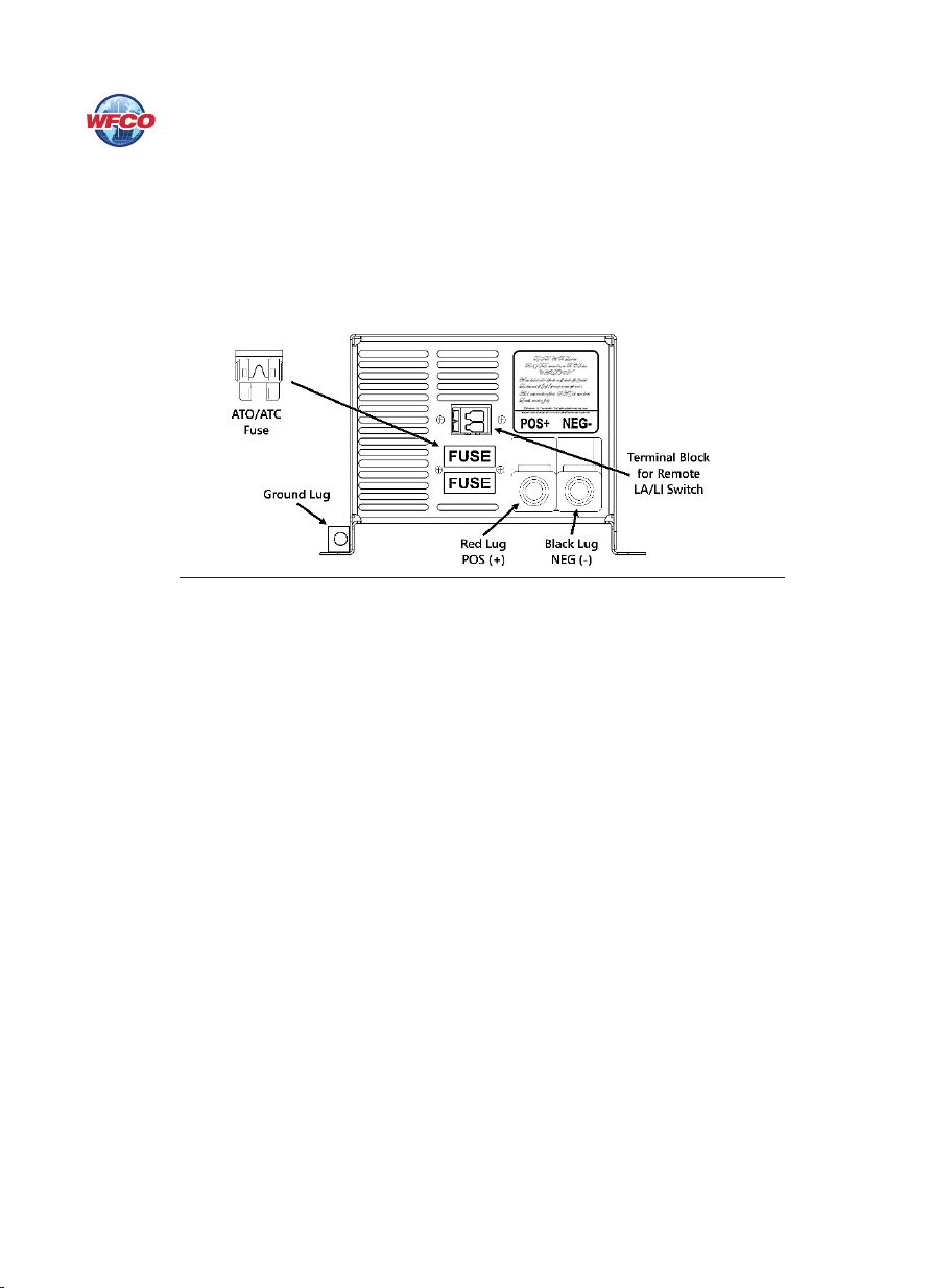
WF-9800LiS Series Converter-Charger Fuses
DC Fuses (12 Volts)
e DC fuse receptacle on the rear panel of the WF-9800LiS Series Converter-Charger has space
for 1 (one) or 2 (two) Reverse Battery Protection fuses (see Figure 1 above). ese fuses should
be replaced with ATC or ATO automotive type fuses, such as Littelfuse type 257 or Bussmann
type ATC. Each converter model requires a dierent Amperage value fuse as follows:
• WF-9835LiS - (1) 40A
• WF-9845LiS - (2) 30A
• WF-9855LiS - (2) 35A
• WF-9865LiS - (2) 40A
• WF-9875LiS - (2) 40A
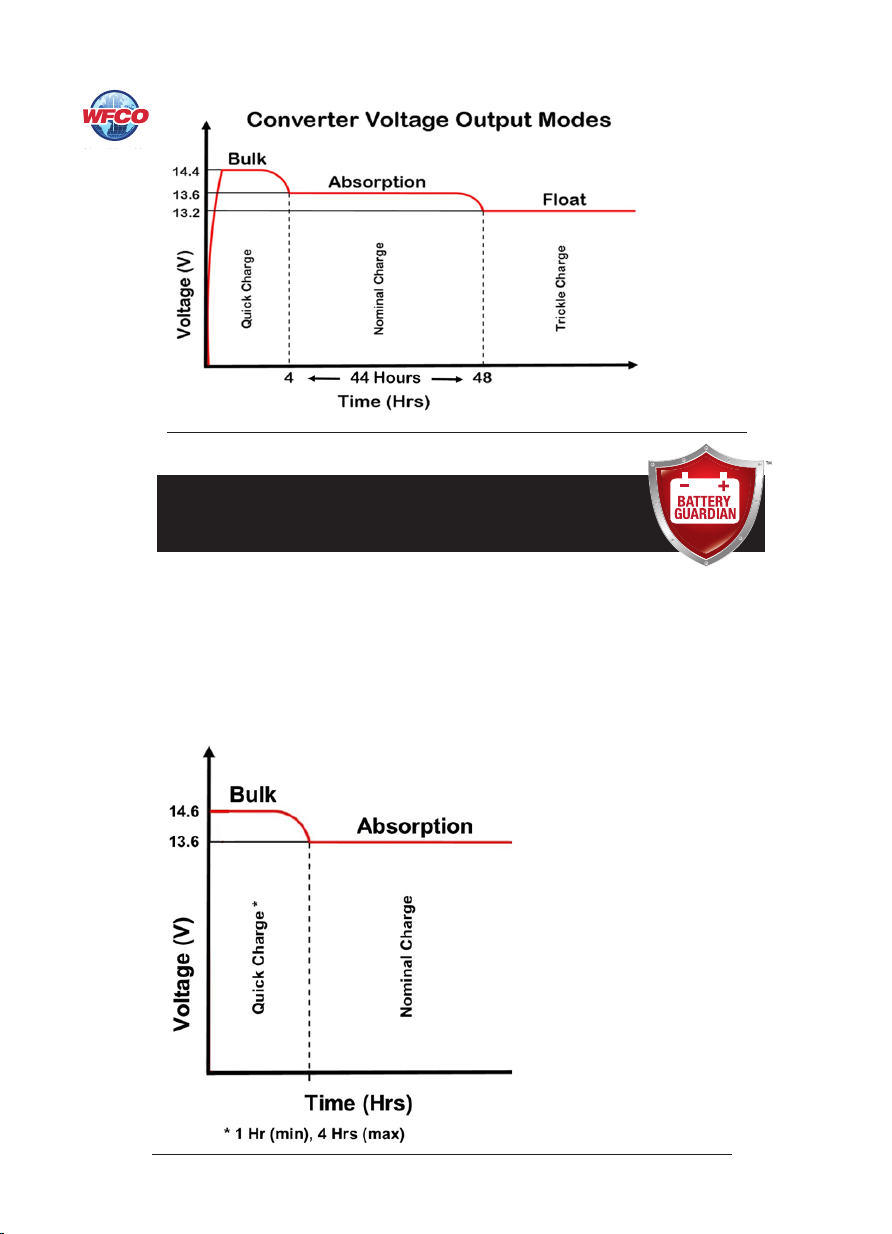
OPERATIONAL FEATURES
Lead Acid Converter Modes
ree-Stage Smart Charging
In order to maximize battery life, it is best to charge batteries slowly, keep them topped o
with a trickle-charge when the RV is not being used. e 3-Stage “smart” charger continuously
measures the battery voltage output and regulates the amount of charge using three modes of
operation; Absorption, Bulk and Float modes.
All WFCO power converters are automatic three-stage switching power supplies. e converter
senses which mode it needs to be in by checking the RV system voltage.
e converter normally provides a constant target output voltage of 13.6 VDC (nominal) to
power all the branch circuits. However, it is current limited, and if the output (load) current
reaches its maximum, the output voltage will drop as necessary to hold the converter’s
maximum output current level (the Amperage rating) without exceeding it.
If the output current reaches its maximum (normally caused by a discharged battery), this will
cause the converter to go into Bulk Mode, which means the target output voltage will change to
14.4 VDC and a timer will start. Although the converter is outputting 14.4 VDC, you will not
be able to read that on a voltmeter due to the voltage-current relationship. From the paragraph
above, as load current increases, output voltage decreases. e actual output voltage will not rise
until the load current is reduced, which happens naturally as the battery charges or if 12 VDC
appliances are turned o.
Bulk Mode will be maintained until the current draw drops to approximately ve Amps, or
until the timer reaches four hours (whichever happens rst). en the target output voltage is
changed back to 13.6 VDC for Absorption Mode. Lights that are powered from the output may
change brightness slightly at that time.
Note: For a detailed explanation of the charging modes, please refer to our publication
“eory of Operation”, document #AD-TD-0001-0.