Wheatstone Corporation AUDIOARTS ENGINEERING DMX Series User manual

1
Networked AoIP Broadcast Console
Manufactured by Wheatstone Corporation

2
Publication Information
©2020 Wheatstone Corporation
Wheatstone considers this document and its contents to be proprietary and confidential. Except for making a reasonable number of copies for your own
internal use, you may not reproduce this publication, or any part thereof, in any form, by any method, for any purpose, or in any language other than English
without the written consent of Wheatstone Corporation. All other uses are illegal.
This publication is designed to assist in the installation and use of the product as it exists on the date of publication of this manual and may not reflect the
product at the current time or an unknown time in the future. This publication does not in any way warrant description accuracy or guarantee the use for the
product to which it refers.
Wheatstone reserves the right, without notice, to make such changes in equipment, design, specifications, components, or documentation, as progress may
warrant, improving the performance of the product.
Trademarks
Product names and other appropriate trademarks, e.g. WheatNet-IP™, VoxPro®, and Vorsis™are registered trademarks of Wheatstone Corporation or its
subsidiaries. Microsoft®and Windows®are registered trademarks of Microsoft Corporation. All other trademarks and trade names are the property of their
respective companies.
Customer Service Contact Information
Wheatstone
600 Industrial Drive
New Bern, NC 28562 USA
For technical support, including on-site service, general product training, repair and parts, contact Wheatstone through our webpage (www.wheatstone.com),
through email at techsupport@wheatstone.com, or by phone (+01 252-638-7000).
Manual Revisions
A = Initial release, October 2017
B = technical corrections, IP Navigator additions, operational clarifications, October 2017
C = Appendix A on networking multiple consoles added; some technical corrections; consolidated software app info into chapter 3, July 2018
D = Added info on a new feature: saving/loading EQ Configuration files (DMX Surface Setup, build 1.0.29 and later), September 2018
D.1 = Added info about saving two Studio EXT selections, October 2018
D.2 = Changed exclamation point graphic to display properly in a PDF, October 2018
E = Clarified note on using mono signals on the Razor along with other minor changes and clarifications. January 2019
F = Updated manual with Audioarts Engineering logo and new DMX Setup & support for WNIP Navigator, January 2020

3
TABLE OF CONTENTS
❖Publication Information .......................................................... 2
❖Safety Instructions & Hazard/Warning Labels ..................... 4
❖1 –Introducing the DMX Console .......................................... 5
DMX Overview .............................................................. 6
DMX Specifications ...................................................... 7
Warranty Statement .................................................... 9
FCC Compliance Statement ......................................... 9
❖2 –DMX Hardware Installation .............................................. 10
Locating the DMX Components .................................. 10
Mix Engine Connections .............................................. 12
DMX Power Up .............................................................. 13
Checking Out the DMX Features ................................. 14
Mix Engine Signal Notes .............................................. 16
Additional DMX Features ............................................ 17
Razor Interface Notes .................................................. 19
❖3 –DMX Apps and Console Configuration ............................ 20
DMX Surface Setup App .............................................. 20
The Navigator App ........................................................ 31
Software Updates ......................................................... 44
❖4 –DMX Operation and Applications .................................... 46
Console Operation ........................................................ 46
Using the Advanced Channel Features ...................... 52
DMX Applications ......................................................... 56
Razor I/O Interface ....................................................... 58
❖5 –DMX Service Information ................................................. 59
❖Appendix A –Creating a WNIP Network .............................. 61

4

5
hanks for joining the growing ranks of broadcasters
employing Audioarts products designed, manufactured, and
supported by Wheatstone Corporation. Throughout our long
history we’ve endeavored to provide the finest quality
products, documentation, and support. To obtain the maximum benefit
from the DMX console’s capabilities, please read through the Introduction,
and Chapters 2 and 3, prior to installing the DMX console. For those in a
hurry, a DMX Quick Guide and a Mix Engine Hook-up Diagram (PDF
files on the USB flash drive that ships with the console) summarize the
console’s physical connections, the software, and Surface controls.
The DMX console has these main components:
●DMX-8 or DMX-16 Surface –This part is commonly referred to as
the “console” since it sits on the countertop and has all board operator
controls. Figure 1-1 shows the DMX-8 Surface. Every DMX
Surface has these features:
●Fader Channels –There are eight identical fader channels on the
DMX-8 and sixteen on the DMX-16. Each fader channel has eight
push buttons with LED illumination (channel on, channel off, cue
on/off, talkback (TB), and four PGM bus assigns), a color Organic
Light Emitting Diode (OLED) display to show channel status, a 100
mm fader, and a rotary Channel Encoder to select the channel
source. The Channel Encoders are also used to access three Ad-
vanced Channel Features: audio mode, panning, and EQ & Dynam-
ics, any of which can be locked out from board operator access.
●Monitor Controls –The console supports a Control Room and an
associated Studio with: CR monitor, CR headphone, Cue, and
Studio Monitor level controls; CR and Studio monitor source
selectors; timer controls; and four Console Event buttons.
●Meter Bridge –Three stereo LED meters display the levels for
PGM 1, PGM 2, and a Switched signal: PGM 3, PGM 4, EXT, and
CUE, when enabled. The Meter Bridge also has a four-digit timer,
bus overload indicators, and an On-Air (Hot Mic) indicator.
●Headphone output –A board operator headphone amp is includ-
ed in the DMX Surface with a ¼” TRS jack on the right side of the
chassis, in-line with the OLED displays.
Figure 1-1 DMX-8 Surface
Figure 1-2 Mix Engine, front panel
●Mix Engine –The 1RU Mix Engine (Figure 1-2) has the audio, logic,
and network connections for the DMX console along with the DSP, sig-
nal mixing, and AoIP (Audio over IP) interface functions.
The Mix Engine has these main features:
●5-port Gigabit Ethernet switch, to network the Surface and Engine,
along with three other Ethernet devices, like an admin PC, audio
playback server, VoxPro PC, Razor I/O Interface, or a main AoIP
gigabit switch to network multiple DMX studios together
●Two low-noise mic preamps, with female XLR inputs, each with
switchable phantom power and input trim control
●Eight stereo/dual mono inputs (four analog and four AES)
●Four stereo program outputs (analog and AES on each output)
●Four stereo analog outputs for Control Room, Studio, Cue, and
operator headphone output for use with an outboard amp
●One 6-port GPIO logic connector
●DC power source for the DMX-8 Surface (the DMX-16 Surface has
a separate in-line DC supply)
T

6
●Installation Kit –The DMX ships with a USB flash drive with PDF
documentation files and the installers for Navigator and DMX Surface
Setup, the two software apps used configure the DMX. Navigator is a
licensed application so a license must be purchased to continue using
the app beyond the 30-day demo license which is included with the
DMX. Contact Wheatstone support (page 59) to obtain a demo license.
DMX-8 consoles include an IEC AC power cord for the Mix Engine and a
DC cable for the Surface. DMX-16 consoles include an in-line DC sup-
ply for the Surface and two IEC AC power cords for the Mix Engine and
in-line supply. All consoles include a short CAT5 cable to connect the
Mix Engine’s Ethernet port to Port 5 on the built-in gigabit switch.
DMX OVERVIEW
The DMX console is a compact, self-contained, Audio over Internet
Protocol (AoIP) radio broadcast and production console which uses the
WheatNet-IP (WNIP) networking convention. Designed for 24/7 operation,
the console has two main hardware components: a 1RU rack mount Mix
Engine, which has all of the console’s audio and logic connections along
with a built-in 5-port gigabit Ethernet switch; and a tabletop board
operator controller called the Surface (which most users consider is the
“console”). Both Surface and Mix Engine are fully FCC and CE certified.
DMX consoles ship with a default configuration so they can be powered
up and used right out of the box. The default settings are changed, to
configure the console for use in an on-air studio, production room,
newsroom, or other application, using the two Windows PC apps included
with the console. Using these software apps is covered in Chapter 3.
Razor I/O Interfaces (1RU, FCC and CE certified) are available to add
audio and logic I/O to any DMX console. Razors use RJ45 jacks
(StudioHub-compatible) for their eight inputs and eight outputs. There are
three I/O styles: all analog I/O plus two mic preamps (Razor 16A); all
AES I/O (Razor 16D); or half analog and half-AES (Razor 16AD). Each
Razor also has one RJ45 Logic jack with six GPIO ports. A Razor connects
to a port on the Mix Engine’s gigabit Ethernet switch using a single CAT5e
or CAT6 cable of up to 330 feet (100 meters).
The DMX can also be networked with any WheatNet-IP Blade to
provide additional audio and logic I/O. To network he DMX with a full WNIP
System, the configuration of the Mix Engine’s built-in Ethernet switch,
which is set for stand-alone operation from the factory, must be edited.
See Appendix A on the configuration setting which needs to be changed to
support networking the DMX with a larger WNIP system.
DMX Surface
The Surface has eight or sixteen audio control channel strips or Fader
Channels. Three of these fader channels are shown in Figure 1-3, along
with the Monitor Controls which are in two columns of controls. Each fader
channel has a large-knob rotary encoder so the board operator can select
the audio source for each fader channel. A channel status display, just
above the on and off buttons, shows the name of the audio source that’s
currently “dialed up” on that channel, along with other source and channel
status information.
When the channel is off, the channel source can be changed by rotating
the channel encoder. This channel display change to show alternate source
names available for that channel, with one name highlighted. Rotate the
encoder until the desired name is highlighted then tap once, or “click” the
rotary encoder to connect the highlighted source to that fader channel.
That signal’s name is then shown in green in the normal channel display.
Each fader channel can be assigned to any combination of Program
buses using the four assignment buttons just below the channel encoder.
Each fader channel has a 100 mm fader for bus level control, plus eight
illuminated switches (Off, On, Cue, Talkback (TB), PGM 1–PGM 4). The
fader channel controls
are identified in Figure
4-2 on page 46.
The Monitor Controls
(the two columns of
controls at the right
end of the Surface)
are identified in Figure
4-4 on page 50. The
left column has the
Control Room controls.
The three top buttons
select the source (PGM
3, PGM 4, or External)
feeding the Switched
Meter. A large user-set
Soft button (no default
setting) is just above
the six Control Room
monitor select buttons
(PGM 1–PGM 4, EXT 1,
EXT 2). These control
the audio going to the
Control Room monitors
and the board operator
headphone output. The
Spilt Cue button sets
how cue is fed to the
headphones (whether
cue even goes to the
headphones is set in
the DMX Surface Setup
app).
Figure 1-3 Surface Controls

7
The right column has the four Event buttons; two large Timer control
buttons; a studio monitor source selector (EXT); and a large Talk to Studio
button (TB).
The CUE/SOURCE, CR, STUDIO, and HDPN controls are rotary encoders
used to control the level of the four dedicated monitor outputs on the Mix
Engine. The two Monitor OLED displays show the current levels of those
four outputs and their status (a red X over a bar graph icon indicates that
output is muted). The CUE/SOURCE and STUDIO encoders are also used to
assign sources to the various EXT buttons. They can also be used to select
and take a “wild source” for the CR and Studio monitor outputs,
respectively.
All Surface controls are on a single field-replaceable Control Panel which
connects to an internal host board using one (DMX-8) or two (DMX-16)
plug-in ribbon cables. This allows for rapid field replacement, with minimal
interruption to operations, in case of spills or other damage to the Surface
controls. Because the program audio flows through the Mix Engine and not
the Surface—except for the audio going to the side panel-mounted
headphone jack, the Surface can be separately powered down from the
Mix Engine without affecting program audio.
Meter Bridge
The integrated direct-view Meter Bridge (Figure 1-4) sits above and
behind the control panel. It has three stereo LED level meters, a four-digit
Timer, and an On-Air indicator. The left meter and middle meters show the
Program 1 and Program 2 bus levels, respectively. The right meter is
switchable between showing the other two program buses (PGM 3 or PGM
4) or an External signal (EXT) like an off-air tuner. The switched meter can
be configured to auto-switch to show the cue levels while cue is active.
The meters normally show both the average and peak levels, but
software settings allow them to be changed to show only the average level
or only the peak levels, for special functions.
Figure 1-4 DMX Meter Bridge
The four-digit Timer is controlled manually, using the Monitor section
S/S button (Timer Start/Stop control), or automatically, when the Auto
Timer button is lit and an audio source, set for Timer Reset (assigned to
specific audio signals using the DMX Surface Setup app) is turned on.
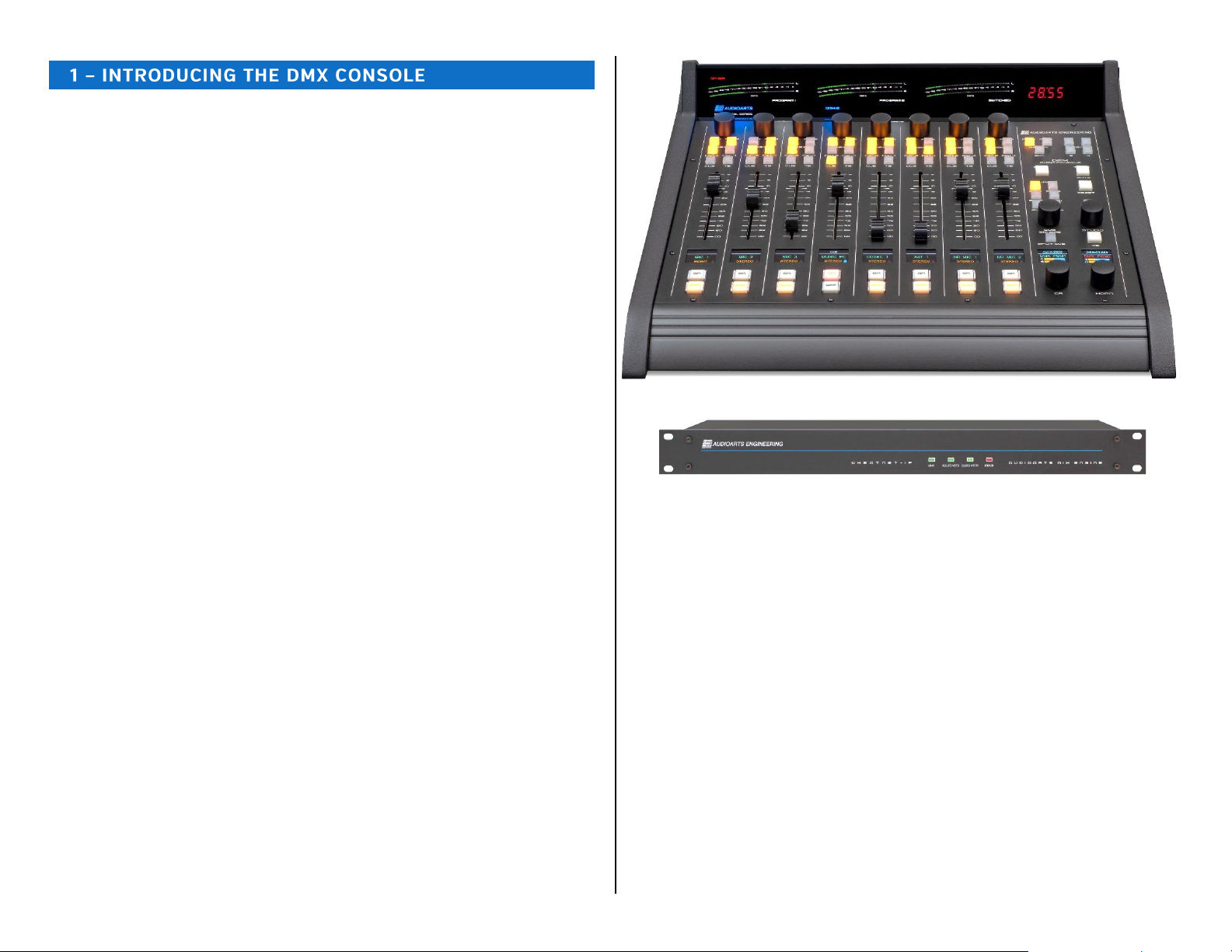
Mix Engine
All audio and logic connections are made on the rear of the Mix Engine
(Figure 1-5). This 1RU device has a 5-port Gigabit switch; two high-
quality low-noise Mic Preamps (with gain control and 48-volt phantom
powering); Signal Processing with EQ and dynamics (applied on a fader
channel basis); eight routable audio inputs (four analog and four AES);
four Program audio outputs (four analog and four AES outputting the
same set of signals); four dedicated analog outputs (to feed powered
Control Room and Studio monitors, powered cue speakers, and an
outboard board operator headphone amp); six GPIO logic contacts
(each independently set to function as a logic input or logic output) and an
Ethernet jack to connect the Engine to the built-in 5-Port Gigabit switch.
Figure 1-5 Mix Engine, rear panel
Input and Output Connectors
All audio, logic, and network connections on the Mix Engine and on the
optional Razor I/O Interface (Figure 1-6)—other than microphone preamp
inputs which have female XLR connectors, use RJ45 connectors and
category wiring (CAT5, CAT5e, or CAT6). Figure 2-4 on page 12 has wiring
pin outs for the RJ45 connectors used to connect analog audio, digital
audio, and logic to/from the DMX console.
Analog and AES wiring conforms to the StudioHub+ convention with two
balanced analog, or one AES/EBU (AES3) signal, per RJ45 jack.
The RJ45 Logic jack has six GPIO logic ports plus a +5V and a GND
connection which use the WheatNet-IP logic jack wiring format.
Figure 1-6 Razor 16AD Interface, rear panel RJ45 Connector Detail
DMX SPECIFICATIONS
Test Conditions:
➢FSD = Full Scale Digital, 0 dBFS = +24 dBu analog
➢0 dBu corresponds to 0.775 volts RMS—regardless of the circuit
impedance, as measured using a 600-ohm circuit.
➢Noise specs measured using a 22 Hz –20 kHz bandwidth. A 30k Hz
bandwidth increases the noise measurement by 1.7 dB.
Wheatstone reserves the right to change the specifications on the following
page without notice or obligation.

8
Mic Preamp
Source Impedance: 150 –600 Ω, balanced
Nominal Input Level: -50 dBu
Input Range: -70 to -31 dBu (using trim control to reach nominal level)
Equivalent Input Noise: -131 dBu
Logic GPIO
Six per RJ45 connector: Connection assignments set using Navigator
(type of logic command and whether it is a logic input or logic output)
Logic Input: Current-limited using internal pull-up. Supports +5 to +12
voltage logic. For a logic low, input voltage must fall below +2.5 volts.
Logic Output: Active low logic which supports +5 to +24 VDC logic, 50
mA nominal, 100 mA max
Analog I/O (Inputs & Outputs: +4 dBu, balanced)
Input Impedance: >10 k Ω, bridging
Optimal Source Impedance: <1 k Ω
Analog In > Analog Out Frequency Response:
+0.0, -0.25 dB, 20 Hz to 20 kHz @ +4 dBu
Analog In > Analog Out THD & Noise:
<0.0025%, 20 Hz-20 kHz @ +4 dBu
Nominal / Maximum Input Level: +4 dBu / +24 dBu
(±18 dB of level gain/trim control available in Navigator)
Output Source Impedance: <10 Ω balanced
Output Load Impedance: 600 Ω optimal
Nominal / Maximum Output Level: +4 dBu / +24 dBu
(±18 dB of output level gain/trim control in Navigator)
A > D Conversion: 24-bit resolution
D > A Conversion: 24-bit, advanced Delta-Sigma
Digital I/O (AES/EBU Inputs & Outputs)
Reference Level: -20 dB FSD (equivalent to analog +4 dBu)
Nominal / Maximum Input or Output Level: -20 dB FSD / 0 dB FSD
(±18 dB of level gain/trim control available in Navigator)
Digital In > Digital Out Frequency Response:
±0.0 dB, 20 Hz to 20 kHz @ -20 dB FSD
Digital Input > Analog Output THD & Noise:
<0.00017%, 20 Hz-20 kHz @ -20 dB FSD
Digital I/O (continued)
Signal Format: AES-3, S/PDIF (inputs only)
AES-3 Input Compliance: 24-bit (uses SRC to support incoming sample
rates of 32 –96 kHz, 16- to 24-bit resolutions)
AES-3 Output Compliance: 24-bit
Output Sample Rate: 44.1 or 48 kHz
Processing Resolution: 24-bit
Surface Dimensions
DMX-08: 4.25" x 17.625" x 17" (H, W, D)
DMX-16: 4.25" x 29.625" x 17" (H, W, D)
Mix Engine Dimensions
A 1RU rack-mounted device:
1.75" x 19.0" x 13.25" (H, W, D)
Razor I/O Interface Dimensions
A 1RU rack-mounted device:
1.75" x 19.0" x 9.25" (H, W, D)
Power Supply
Type: Internal switching supply on the Razor and the Mix Engine, which
also powers the DMX-8 control surface; the DMX-16 Surface uses a
separate in-line DC power supply
AC input: Detachable IEC cord
AC input: 90-240 VAC, 50/60 Hz
Output: +16 VDC @ 1 amp (PWR OUT jack on Mix Engine)
Output: +16 VDC @ 2.67 amps (DMX-16 Surface in-line supply)
Power Requirements
Mix Engine: <27 watts at 120 VAC / 60 Hz
DMX-08 Surface: <10 watts at 120 VAC / 60 Hz
DMX-16 Surface: <20 watts at 120 VAC / 60 Hz
Razor: <15 watts at 120 VAC / 60 Hz
Environment
Ambient Temperature: Less than 40°C
Cooling: Convection cooled, no fans

9
WARRANTY STATEMENT
LIMITED WARRANTY BY WHEATSTONE CORPORATION
1. All equipment sold and shipped to final destinations within the USA and its
possessions warranted for one (1) full year from the date of purchase against
defects in material and workmanship. All equipment sold and shipped to final
destinations outside the U.S.A. and its possessions warranted for one (1) full
year from the date of purchase against defects in material and workmanship.
All repairs to maintain the unit at original specification will be made at no
charge to the original purchaser, except for shipping and insurance costs to be
prepaid by the owner to the factory in the event the unit cannot be serviced by
an authorized Wheatstone Corporation dealer.
2. This Warranty is subject to the following restrictions and conditions:
a) The owner must have filled out the enclosed Warranty Card and returned
it to Wheatstone Corporation; or at the time of servicing the owner must
provide proof of purchase from an authorized Wheatstone Corporation dis-
tributor or dealer.
b) This Warranty is valid for the original purchaser on the unit. Parts used for
replacement are warranted for the remainder of the original warranty pe-
riod. Repair or replacement is in the discretion of Wheatstone Corporation
and is the exclusive remedy hereunder.
c) This Warranty DOES NOT apply to damage or defects resulting from abuse,
careless use, misuse, improper installation, electrical spikes or surges, or
alteration, repair, or service of the unit or equipment by anyone other than
Wheatstone Corporation or its authorized dealer.
d) This Warranty is void if the serial number has been removed, altered or
defaced.
e) This Warranty DOES NOT cover loss or damage, direct or indirect, arising
out of the use or inability to use this unit or for shipping or transportation
to any dealer.
f) Wheatstone Corporation reserves the right to modify or change any unit in
whole or in part at any time prior to return delivery in order to incorporate
electronic or mechanical improvements deemed appropriate by the
Wheatstone Corporation but without incurring any responsibility for modi-
fications or changes of any unit previously delivered or to supply any new
equipment in accordance with any earlier specifications.
g) THERE ARE NO OTHER WARRANTIES, EXPRESSED, IMPLIED, OR STATUTO-
RY, INCLUDING ANY WARRANTIES OF MERCHANTABILITY OR FITNESS
FOR A PARTICULAR PURPOSE. IF FOR ANY REASON, ANY IMPLIED OR
STATUTORY WARRANTY CANNOT BE DISCLAIMED, THEY ARE LIMITED TO
THIRTY (30) DAYS FROM THE DATE OF PURCHASE. WHEATSTONE CO-
PORATION IS NOT RESPONSIBLE FOR ELECTRICAL DAMAGE, LOSS OF USE,
INCONVENIENCE, DAMAGE TO OTHER PROPERTY, OR ANY OTHER INCI-
DENTAL OR CONSEQUENTIAL, WHETHER DIRECT OR INDIRECT, AND
WHETHER ARISING IN CONTRACT, TORT, OR OTHERWISE. NO REPRE-
SENTATIVES, DEALERS, OR WHEATSTONE PERSONNEL ARE AUTHORIZED
TO MAKE ANY WARRANTIES, REPRESENTATIONS, OR GUARANTIESS OTH-
ER THAN THOSE EXPRESSLY STATED HEREIN.

10
ach DMX Surface is 17” (43.2 cm) deep and 4 1/4" (11 cm)
tall. The DMX-8 Surface is 17 5/8" (45 cm) wide. The DMX-
16 Surface is 29 5/8” (75.3 cm) wide.
The Mix Engine (1RU) mounts within the studio
cabinetry near the Surface location. Install at least one 1RU blank panel
above the Mix Engine to ensure adequate ventilation. DMX components are
convection cooled allowing them to be mounted into any studio, including
ones with active microphones, without adding any environmental noise.
When locating the DMX Surface and Mix Engine, avoid proximity to devices
which may generate electromagnetic fields, such as large power
transformers, motors, and audio amps using switching supplies.
LOCATING THE DMX COMPONENTS
The DMX Surface is intended to set on top of the studio furniture
countertop with its palm rest between six and twelve inches (15 to 30 cm)
from the edge of the countertop (Figure 2-1). This “setback space” allows
keyboards and mice, a VoxPro controller, copy, log sheets, etc. to be set in
front of the console.
The Mix Engine (1RU) is typically rack mounted into a 19” rack located
below the countertop. We recommend adding a 1RU vented panel both
above and below the Mix Engine for ventilation. Mount the Mix Engine so
its rear panel is easily accessible since that’s where the DMX audio, logic,
and network connections are made.
With a DMX-8 Surface, a 16-foot locking DC cable (included) connects
the DMX Surface to the PWR OUT jack on the back of the Mix Engine. This
constrains are far away the Mix Engine can physically be located since the
DC cable must not be under strain when connected between the DMX
Surface and Mix Engine.
Note: The in-line DC supply used with the DMX-16 Surface
(Wheatstone # 980064) can be used to power a DMX-8 Surface if
the Mix Engine must be mounted beyond the reach of the included
16-foot DC cable.
The DMX-16 Surface includes an in-line DC supply with a captive DC
cable and detachable IEC AC cord. An isolated AC outlet must be located
below the countertop to allow the six-foot DC cable to plug into the
Surface and the six-foot AC cord to plug into an AC outlet.
The Surface Ethernet port connects to Port 4 on the Mix Engine’s rear
panel Ethernet switch using a straight-thru category cable (customer
supplied CAT5e or CAT6 cable).
The DMX Surface is typically just set onto the countertop since its weight
(16 lbs. for DMX-8, 26 lbs. for DMX-16) and four large rubber feet should
hold it in place. If the Surface needs to be fastened to the countertop for
security reasons, a step-by-step procedure is listed in the section
Fastening the Surface to the Countertop, on page 11.
Figure 2-1 DMX-8 Surface, Countertop Positioning
For the cleanest installation, we recommend drilling a one- to two-inch
cable access hole through the countertop for the Surface wiring. Only the
customer supplied CAT5e / CAT6 cable and the DC power cable connector
must pass through this hole, so hole size is not critical. The hole could be
sized to match an available hole grommet, or it could be left raw since it’ll
be covered by the Surface.
E

11
Here are the steps to drilling the cable access hole:
1. Position the Surface on the countertop so that the palm rest is
parallel to the countertop edge and is setback the desired amount
(typically, between six and twelve inches).
2. Use a pencil to mark the countertop at the center of the front edge
of the palm rest (for the DMX-8, this is the center line between
fader channels 5 and 6, as shown in Figure 2-1).
3. Move the Surface out of the way and mark a point 13” behind the
palm rest mark, perpendicular to the countertop edge. This marks
where the one- to two-inch cable access hole will be drilled.
4. Drill the cable access hole through the countertop.
Surface Placement & Cable Connections
Before setting the Surface back into position, remove the upper rear
cosmetic cover by removing the black #1 Phillips screws. The top of the
cover fits into a slot in the Meter Bridge top cover, so it may have to be
pulled down slightly to remove it from the slot. When removed, the host
control board, with the DC power jack and RJ45 Ethernet jack is revealed.
Figure 2-2 Surface rear view (upper rear cover removed)
Route the DC and category cables up through the countertop hole and
through the two lower chassis access holes (Figure 2-2). Plug and latch the
category cable into the RJ45 Ethernet connector. Plug the DC cable into
the DC power jack tightening its housing onto the threaded jack.
Reattach the upper rear cover then set the Surface into position on the
countertop.
On a DMX-8 Surface, route both the DC and category cables to the back
of the Mix Engine (Figure 2-3). Plug the category cable into Port 4 on the
built-in ETHERNET switch. On a DMX-8 Surface plug the DC cable into the
PWR OUT jack, tightening its housing onto the threaded jack.
On a DMX-16 Surface, or on a DMX-8 that is using the in-line supply,
route the category cable to the Mix Engine and plug it into Port 4 on the
ETHERNET switch. Plug the in-line DC power supply’s IEC AC cord into an
isolated AC outlet.
Figure 2-3 Mix Engine, Rear Panel Partial View,
Ethernet and DC Power Connections
If not connected already, connect the short category cable supplied with
the Mix Engine, from the ETHERNET jack to Port 5 on the Ethernet
switch, as illustrated in Figure 2-3
Fastening the Surface to the Countertop
If the DMX Surface must be fastened to the countertop for security
reasons, the two front feet from the chassis must be removed. The
Surface’s control panel (identified in Figure 2-1) must also be removed.
Two #6 screws, with oversize washers and lock washers, are required.
Their length must extend through the countertop, from below, and go
through the two front feet with just enough thread left to fasten to the
chassis. The two screws must not extend over ¼” into the chassis when
tight to avoid contacting the control panel circuit board or internal cabling.
The cable access hole must already have been drilled (per the four steps
listed earlier) and the two Surface cables must have already been run
through the hole and plugged into the Surface. The Surface must be
unpowered during this procedure:
1. Unscrew the two front feet. Retain the two #6 screws, lock
washers, and flat washers for possible future reuse.
2. Remove all of the screws, using a 1/16” hex driver, from around
the edge of the control panel. Lift the panel up slightly to unplug
one ribbon cable on a DMX-8 or two ribbon cables on a DMX-16.
Set the control panel onto padded material.
3. With the Surface set into position, mark the countertop through
the front two feet and mounting holes using a pencil a thin center
punch, or even the 1/16” hex driver.
4. Move the Surface aside and drill a 3/16” hole at each mark
completely through the countertop.

12
5. This step requires two persons. One person inserts and holds the
two long #6 screws (each with lock and oversize washers) through
the countertop from below with the appropriate screwdriver for the
two screws.
A second person sets the two feet onto the screws and then aligns
the Surface over the screws, holding it in position as the two long
#6 screws are tightened. Make sure the Surface remains parallel
with the countertop edge as the screws are tightened. Do not
compress the two rubber feet and verify the end of the screws do
not extend more than ¼” above the chassis.
6. Set the back edge of the control panel onto the Surface chassis
and plug in the ribbon cable(s). Set the control panel back down
onto the chassis and reinstall the mounting screws.
MIX ENGINE CONNECTIONS
To facilitate wiring the Mix Engine, create a wire list, listing all
connections to and from peripheral devices. Identify and create labels for
each end of each audio, logic, and network cable. List these connections in
a master facility wiring logbook to ease installation, future system wiring
and equipment changes, and system troubleshooting.
Route all audio cabling to/from the Mix Engine with the maximum
practical distance from all AC mains wiring. The Surface’s power cable only
carries DC voltage, so audio wiring can run parallel to or even be tie
wrapped with this cable without issue.
Line level analog, AES/EBU, and logic wiring connect using RJ45 jacks on
both the Mix Engine and Razor. Analog line-level inputs and outputs are
balanced +4 dBu signals which connect only the plus (+) and minus (-)
signals from the peripherals.
Each signal on the audio and logic RJ45 jacks is identified in Figure 2-4.
Note that the wire colors listed are for EIA/TIA T568B wiring (straight-thru
patch cable wiring) but that category cables may be wired using the T568A
standard, which swaps the Orange and Green wire pairs with WHT/GRN on
terminal 1, GRN on terminal 2, WHT/ORG on terminal 3, and ORG on
terminal 6.
Shielded twisted pair (STP) and unshielded twisted pair (UTP) wiring can
be used interchangeably with balanced signals and with logic signals.
When crimping CAT5 cables, UTP has an advantage as it’s a lot easier to
hand crimp than STP wiring.
To simplify your audio wiring, use standard lengths of straight-thru CAT5
cables along with RJ45 Audio Adapters to plug into peripheral device jacks.
Angry Audio and other vendors make a wide variety of RJ45 Audio
Adapters, most of which are carried by Audioarts and Wheatstone dealers.
For more information on RJ45 cable adapters for audio wiring refer to this
web page: https://angryaudio.com/studiohub/
Figure 2-4 Audio & Logic RJ45 Pin Outs & Signals
To simplify logic wiring, NotaBotYet (www.notabotyet.com) has GPIO
Logic Adapters for the Logic connectors on the Mix Engine, Razor, and
Blades. A straight-thru CAT5 cable connects the RJ45 Logic jack to the
GPIO Logic Adapter, which then breaks out the six GPIO connections to
screw terminals for wiring “old school” hard-wired peripherals, like warning
light interfaces and hot mic LEDs.
When wiring directly from an RJ45 jack on a Mix Engine, Razor, or Blade
to individual XLR, TRS, or other audio connectors, single-pair UTP
(DataMax 5100 or similar) can be used to wire AES or mono analog
connections. Dual-pair UTP (DataMax 5200 or similar) can be used for
wiring to stereo connections when a single connector (like a D-Sub) is
used on the peripheral device.
When wiring a stereo analog device with two connectors, use two single-
pair UTP wires connected to a common RJ45 for the cleanest connection to
the two audio plugs. Alternately, separate out the ORG and GRN wire pairs
from a standard CAT5 cable to wire to the two audio plugs. For a clean
installation, cover each wire pair with tubing held in place with a short
piece of shrink tubing over the ends of the tubing and the CAT5 jacket.
The female XLR jacks are designed for microphone cables wired using
shielded wiring specifically for low-level balanced mic signals. A monitor
output which feeds a powered monitor speaker may also require using
shielded cable. In that case the shield terminates at the monitor speaker
end since there’s no shield connection on the Mix Engine’s RJ45 jacks.
Note: StudioHub+ wiring has pin 4 as DC Ground to support PoE
(Power over Ethernet). Mix Engine, Razor, and Blade RJ45
connectors do not tie pin 4 to ground since these products do
not support PoE. Thus, a ground connection can only be made at
the peripheral device end. If the peripheral device has unbalanced
inputs, with a Tip-Sleeve or RCA connector, a signal matchbox or
an audio balun transformer (balanced in, unbalanced out) must be
placed in-line to properly unbalance the balanced output signal.

13
An unbalanced output device can directly connect to a DMX analog
input by connecting its low (-) signal wires (pin 2, ORG, and/or pin 6,
GRN) to GND on the unbalanced device. Connect the hot wire (the
unbalanced signal) to the WHT/ORG and/or WHT/GRN wires (terminals 1
and 3). Since unbalanced devices have lower output levels—as compared
to a balanced signal, use Navigator’s Device > Sources tab to raise the
input. Any DMX input can be increased by up to +18 dB.
When a DMX analog output needs to connect to an unbalanced device,
a matchbox or audio balun transformer (balanced-to-unbalanced) must be
used.
Note: On Mix Engine, Razor, or Blade outputs, do not connect the
low (-) signals (ORG and GRN wires) to ground at the unbalanced
device to directly connect an unbalanced device. This will lead to
phase and crosstalk issues. It can also lead to component failure
over time since this shorts an active op amp output to ground.
Ethernet Connections
Ethernet network wiring also uses RJ45 jacks but, because a WNIP
network is running at 1000Base-T (1 Gigabit or 1 GB) only CAT5e or CAT6
cabling should be used. For a short connection, like connecting the Mix
Engine to Port 5 or the Surface to Port 4 on the Ethernet switch (Figure
2-3 on page 11), a CAT5 cable could be used, but for all longer cable runs
only CAT5e or CAT6 cables should be used.
Ports 1, 2, and 3on the five-port Gigabit Ethernet switch are available
to connect a Windows PC running the DMX Surface Setup and
Navigator. This PC won’t need to be connected during normal use unless
Navigator is needed to change signal connections. Alternately, if a VoxPro
or other audio editor PC is networked with the DMX, the apps could be
installed on that PC. Any open switch ports are available to network a
WNIP-compatible media server, a Razor I/O Interface, or any WNIP Blade.
Port 1 can also be configured so the DMX can connect to an AoIP switch
to network it with additional WheatNet consoles, Blades, Razor I/O
Interfaces, and WNIP-compatible media severs in a larger WNIP network.
Appendix A has details on changing the built-in Ethernet switch’s
configuration settings to support connecting to a WNIP network.
DMX POWER UP
The Mix Engine, Razor I/O Interfaces, and Blades do not have power
switches since all are designed for continuous 24/7 operation. All are
designed to work with AC mains supplying 90-240 VAC at 50/60 Hz. For
the most reliable operation, all DMX components should only plug into
isolated ground circuits (orange outlets in the USA) which are ideally on a
UPS (Uninterruptible Power Supply).
On a DMX-16, plug in the Surface Supply. On a DMX-8 or DMX-16 plug
the IEC AC cord into the Mix Engine. It takes about 90 seconds for each
DMX device to boot up, connect to the WNIP network, and be ready for
use. If the DMX-16 Surface is powered up without being networked to a
Mix Engine, or if the Mix Engine itself is not powered, the meter bridge
level displays’ peak LEDs will scan upwards on all meters to visually
indicate that the Surface is not properly communicating with its Mix
Engine. Once the Surface and Mix Engine are properly connected via
Ethernet, the meters’ LEDs stop scanning.
When power is first applied to the Mix Engine, the rear panel green On
LED (next to the Ethernet switch) lights up first. This is followed by the
green LEDs blinking on active Ethernet switch ports. Note that the Surface
Ethernet jack only blinks one LED since it communicates at 100Base-T.
The Mix Engine and Razor ports will have both green LEDs blinking since
they both communicate at 1000Base-T. A networked PC will also only blink
one LED if its NIC does not support gigabit speeds.
The front panel LINK LED (Figure 2-5) lights up solid when the Mix
Engine’s Ethernet jack is connected to port 5 of the Ethernet switch. On a
stand-alone DMX, the other two front panel green LEDs: ROUTE MSTR
(Route Master) and CLOCK MSTR (Clock Master) also light up solid—after
about 90 seconds, indicating the Mix Engine is ready for use.
Figure 2-5 Engine Front Panel Status LEDs
When a DMX is networked with existing WNIP consoles, the new Mix
Engine will most likely not be designated as a master, thus its ROUTE
MSTR and CLOCK MSTR LEDs could both be off. This simply indicates
there’s another Mix Engine or Blade in the WNIP network which are set as
the Route Master and Clock Master. With multiple Mix Engines or Blades in
a WNIP system, one Blade will be designated as the Route Master while a
second Blade will be designated as the Clock Master.
If the red ERROR LED should ever light, it indicates an error condition
has occurred within the Mix Engine. To reset this error, first try rebooting
the Mix Engine using Navigator. If the red LED remains lit after the Mix
Engine reboots, power cycle the Mix Engine (unplug the AC cord from the
Mix Engine, wait five seconds then plug the AC cord back in).
If the red Error LED lights up again after the Mix Engine restarts it
indicates a serious fault which requires service. Contact Wheatstone
technical support for assistance. See Chapter 5 (page 59) for information
on obtaining service and support for your DMX console.

14
CHECKING OUT THE DMX FEATURES
Once the Mix Engine and Surface are connected to Ports 4 and 5 on the
built-in Ethernet switch, and are powered up, on a stand-alone DMX the
Surface and Mix Engine should appear as shown in Figures 1-1 and 1-2 on
page 5.
Note: Figure 4-2, on page 46, identifies each fader channel control
and Figure 4-4, on page 50, identifies each monitor control.
On Fader Channel 3, with the channel turned off, rotate the Channel
Encoder. The channel’s normal display switches to show a list of source
names (Figure 2-6). The middle name is highlighted with the name of the
device that it’s on listed above the white line. Blade01 is the default name
assigned at the factory to each Mix Engine.
Figure 2-6 Selecting a Channel Source
Rotate the encoder clockwise to move the highlighting down the
alphanumeric list of names. Rotate the encoder counterclockwise (CCW) to
move the highlighting up through the names. The names wrap to present
a continuous list. NoSource, which appears at the top of the list, is a good
way to identify when the names have wrapped around.
Every physical input on the Mix Engine has a signal name of up to eight
characters. The default names all start with BL, for Blade, followed by that
Blade’s ID number (1 is the ID number for a new Mix Engine). The default
names end with a signal number, like S02, to identify the physical
“Source” or jack on the Mix Engine, Blade, or Razor. Likewise, the Mix
Engine outputs are identified using unique names to identify each
Destination: CB001CR (Console Blade 1, Control Room) CB01PGMA (the
analog and AES outputs for PGM 1) and so on.
All DMX inputs are set as stereo—except for Analog Input 1, which is
set as dual mono and assigned the names BL01MIC1 and BL01MIC2. The
three remaining Analog inputs are BL001S02, BL001S03, and BL001S04.
The four AES inputs have the default names of BL001S05 thru BL001S08.
These match the jack numbers (1 –8) on the Mix Engine’s rear panel.
Analog input 1 is meant to connect to MICS OUT so that the two mic
preamps can be used without making any configuration changes. If the
built-in mic preamps are not used, Analog Input 1 can be changed to a
stereo input using Navigator.
As the encoder is turned CW past the Mix Engine’s physical input signal
names, the internal signals within the DMX are listed. Many, if not most, of
these signals are typically not set as “visible” on fader channels, but on a
new console every source signal is set visible to ease installing and
configuring the DMX. Setting which signals are visible is set using the DMX
Surface Setup App.
Rotate the channel 3 encoder so that BL001S02 is highlighted, as
shown in Figure 2-6. Press once on the channel encoder knob to select
that signal. This is called “clicking” the encoder–just like clicking a PC
mouse button. That connects the highlighted signal to the channel.
BL001S02 is then shown, in green, in the middle of the channel 3 display
(Figure 2-7).
The OLED displays are divided by a white line in the normal display. The
space above the line indicates when cue, equalization, and dynamics are
active on that channel (Figure 2-7). Icons for the High Pass and/or Low
Pass Filters are also shown when they’re active. EQ (for Equalization) and
DYN (for Dynamics) are shown when they’re active. From the factory, mic
processing is active on channels 1 and 2, and are turned on, hence the EQ
and DYN indications on those two fader channels.
Figure 2-7 Displays for Channels 2, 3, and 4
Below the source name, in orange, is the channel’s mode setting. The
default setting for every channel is STEREO (mono signals like mics are fed
to both left and right channels by default).
To either side of the mode name are icons to indicate source status. On
the right side is a lock icon to indicate that source’s LIO status (logic
control status. On the left side—if the channel source is identified as a mic,
there’s a mic icon which turns red while that channel is on.
Advanced Channel Features
Each channel has three Advanced Channel Features: Mode,Pan,and
EQ & Dynamics, which are accessed by “double-clicking” or quickly
pressing twice on the channel encoder knob. The advanced features are all
unlocked when the DMX ships from the factory.
“Double-click” the channel 3 encoder (tap it twice quickly). Mode now
appears above the white line. Rotating the encoder, while Mode is shown
in the display, steps through the four audio modes (Right, Left, Mono, and
Stereo) that the channel can be assigned. Make sure STEREO is shown
then double-click the encoder again.

15
Pan is then shown above the white line. Now, rotating the encoder pans
or balances the signal toward the left or right channel. Readjust the
encoder so CENTER is shown then double-click the encoder again.
The channel 1 - 8 OLED displays switch to show EQ & Dynamics control
screens. The initial display screens show whether EQ & Dynamics are
turned on or off on that channel. Additional screens show the EQ &
Dynamics settings. On fader channels 1 and 2, EQ and Dynamics are
assigned by default for “light mic processing” since these channels are
typically assigned to a Host and a Guest mic. The remaining fader
channels do not have any EQ or Dynamics settings applied. For now,
double-click the channel encoder again. The eight channels will switch
back to their normal displays showing their current source names.
Note: The Mode, Pan, and EQ & Dynamics controls should be
selectively locked out from board operator access prior to releasing
the console for daily use. This is done using the Talent Access page
tab in the DMX Surface Setup app (see page 23).
Connecting Audio
To understand the audio connections and DMX Surface controls, connect
a stereo analog audio signal, like a +4 dBu test tone from a tone generator
or test CD, to the ANALOG 2 IN jack on the Mix Engine (Figure 2-9 on the
next page shows the Mix Engine jacks). This audio input is named
BL001S02 and is the Channel 3 source that was set in the previous
section.
Assign channel 3 to PGM 1,PGM 2,PGM 3, and PGM 4 (all four
assignment buttons are lit). Set the channel fader so the middle line on
the fader knob aligns with the two arrows at the -12 dB position. This sets
that channel for unity gain. Turn Channel 3 on by pressing and releasing
the On button directly below that channel’s display. The button turns red
indicating that BL001S02 is now feeding the assigned Program buses.
If the input signal is a +4 dBu test tone, then all green meter segments
will be lit along with the first yellow segment, which indicates -20 dBFS
(decibels Below Full Scale). This equals 0 VU on an analog VU meter. The
Program 1 and Program 2 meters should both show this level. The
Switched Meter should also show this level when the Meter PGM 3 or
Meter PGM 4 button is lit in the monitor section.
Connect an analog test set to each of the four PGM ANALOG outputs to
confirm each has +4 dBu out. Connect a digital test set to each of the four
PGM DIGITAL outputs, which have the same signals as the analog jacks, to
confirm that each has a -20 dBFS output. The default sources connected to
the four PGM outputs are the PGM 1 to PGM 4 buses.
To check the monitor outputs (the four OUT jacks), connect a test set or
a powered monitor speaker with a balanced input to the CR Out jack. In
the left column of the monitor section, select PGM 1 as the monitor source
for the Control Room. DMX PGM1 will be shown in the left monitor display
(Figure 2-8). Adjust the CR encoder to set the volume of CR Out. Its
relative output level is indicated by the bottom bar graph, with the speaker
icon, in the left monitor OLED display.
Figure 2-8 Monitor Displays
Move the test output to the HDPN Out jack. Its output level, and the
DMX Surface’s headphone jack level, is adjusted using the HDPN
encoder. Its level is indicated by the bottom bar graph in the right display
with the headphone icon. It has the same monitor source as CR Out.
Move the test output to the STU Out jack. Its current monitor source is
shown in the right-hand display. If NoSource appears in the right-hand
display, an on-the-fly monitor source can be set for the Studio by
press/holding, for about three seconds, the STUDIO encoder. A list of
source names appears in the right-hand display. Rotate the Studio encoder
to highlight DMX PGM2 then click the Studio encoder to assign that source
as the Studio monitor source, as shown in Figure 2-8.
With a source selected, use the Studio encoder to adjust the STU Out
volume. The studio monitor level is indicated by the upper bar graph in the
right display with the speaker icon.
Move the test output to the CUE Out jack. Press Cue on channel 3 (it
lights, and CUE is shown in the channel display). Use the CUE/SOURCE
encoder to adjust the cue volume. The upper bar graph in the left display,
with a C, indicates the cue output level. Note that even though this is a
“stereo” or two-channel output, the DMX cue output is mono.
Note: If you followed all the steps in the Checking Out the DMX
Features section, you should have a good understanding of how to
connect audio into and out of the Mix Engine and how to use the
DMX Surface controls. The rest of this chapter covers specific
details on the audio and logic jacks found on the Mix Engine and
the Razor Interface.
Chapter 3 (starting on page 20) covers how to install and use the
supplied apps (DMX Surface Setup and Navigator) to name the
DMX signals, add logic control, and how to configure the DMX
console for your specific application.

16
MIX ENGINE SIGNAL NOTES
This section covers each Mix Engine connection and how the apps are
used to configure that signal or connection. Figure 2-9 shows the audio
and logic jacks on the back of the Mix Engine.
Figure 2-9 Mix Engine, rear panel, Audio & Logic Jacks
Mic Preamps –The two female XLR jacks connect to the Mix Engine’s
two on-board low-noise mic preamps. Any type of dynamic or condenser
mic can be plugged in to boost the mics up to line level. The line level
outputs of the two mic preamps are on the MICS OUT jack which is
typically jumpered to ANALOG IN 1. These mics are typically assigned to
fader channels 1 and 2, which have factory-set EQ and Dynamics
Processing already applied, so an external mic processor is not required
with the DMX. If additional mic preamps are needed the Razor 16A
Interface has two mic preamps and the M4IP-USB Blade has four SQ
mic preamps, along with Vorsis Embedded mic processing, plus four USB
ports and local analog and AES outputs for headphone and studio monitors
or recording outputs.
Each preamp has a gain control and a recessed phantom power switch
on the back panel. For a dynamic mic set the phantom power switch to off
(+48V LED is off). To power a condenser mic set the phantom switch to
on (+48V LED is lit yellow).
Note: Leave the phantom power switch set off until the condenser
mic and its mic cable is plugged in, then turn on the phantom
power. When a condenser mic must be unplugged, turn off
phantom power before unplugging the mic or unplug the cable at
the Mix Engine and then unplug the microphone.
MICS OUT –This jack has the line level outputs from both mic
preamps: Mic Preamp 1 is the left signal and Mic Preamp 2 is
the right signal. Connect a short straight-thru CAT5 cable from
MICS OUT to ANALOG 1 IN since that input is preset for two
mono mic signals rather than for a stereo signal as are all other
Mix Engine inputs.
The Gain controls are adjusted, once the mics are wired and
the Mics Out jack is connected to the Analog 1 In jack, using the
Navigator app’s Blade > Source tab, which has a Level Meter for
each input on the Mix Engine. With the talent speaking at their
normal “radio voice level” adjust the mic Gain pot so the top of
the green bar graph signal is near -20 dBFS which typically
means their peak LED will be around -8 dBFS.
LOGIC - The Mix Engine and Razor Interfaces each have one RJ45 Logic
jack for connecting logic to non-IP external devices like a Henry warning
light interface, a Mic Arm LED, or a CD player. Each Logic jack has six LIO
logic ports (on pins 2–7) plus ground (on pin 1) and +5 volts (on pin 8).
Each logic port is independently assigned, using Navigator, to function as a
logic output like On Tally, Studio In Use tally, Start Pulse, etc., or as a
logic input like Channel On, Channel Off, Ready, Cue, etc.
Each Mix Engine also has 128 Soft LIO (SLIO) logic signals which can be
used by WNIP-compatible devices, like talent stations and media servers,
for bi-directional command and control of the DMX console over Ethernet.
SLIO signals are also assigned using Navigator. Each can be set as either
an input or an output. See Assigning Logic (starting on page 42) for details
on assigning both LIO and SLIO logic.
ANALOG IN - The ANALOG IN 1-4 inputs are designed for balanced +4
dBu signals. Unbalanced, -10 dBv, signals can also be directly connected,
without needing a match box, since each input has input gain and balance
controls in Navigator (see Level & Balance Controls on page 41).
The inputs have the default names: BL01MIC1 (input 1 left), BL01MIC2
(input 1 right), BL001S02 (input 2), BL001S03 (input 3), and BL001S04
(input 4) in DMX signal lists. Any input can be separated into two mono
inputs (see Changing the Signal Type on page 40) to allow two mono
signals to connect to one RJ45 jack.
DIGITAL IN –The DIGITAL IN 5–8inputs are designed for stereo
differential AES/EBU (AES3) signals which, in most cases, can alternately
have an unbalanced S/PDIF digital signal connected. Their default names
are BL001S05 –BL001S08 in the signal list. They have the same gain and
balance controls in Navigator as analog signals and any AES/EBU input can
also be split into two mono signals for connecting digital phone systems.
Digital In 8 can also be used as a Sync Reference input to synchronize the
DMX to an external sample clock signal.
PGM OUTPUTS –There are eight PGM Outputs (four stereo balanced
analog and four AES/EBU) which, by default, are cross connected to the
PGM 1 –PGM 4 buses. These four destinations are named CB01PGMA –
CB01PGMD in signal lists. Any source can cross connect to these
destinations, but they cannot be split for dual mono out operation and the
same signal is applied to both the analog and AES/EBU outputs.
Note: If you change the source cross connected to any PGM or
Monitor output, uncheck the DMX Surface Setup option Use Default
Signal Mapping (see Input/Output on page 23) since that option,
when checked, will reconnect the four PGM buses to the PGM
outputs, and the default Monitor sources to the four Monitor
outputs, whenever the Mix Engine or DMX Surface is rebooted or
powered.

17
Note: The four AES/EBU outputs can only connect to balanced
AES/EBU inputs. Connecting an AES/EBU output to an unbalanced
S/PDIF input does not work. A signal translation device is required
to convert an AES/EBU output into an S/PDIF signal.
MONITOR OUTPUTS –The four stereo analog output jacks: CUE, CR,
STU, HDPN have the destination names: CB01CUE, CB01CR, CB01STU,
and CB01HDPN. Normally, the sources DMX CUE, DMX CR, DMX Stu, and
DMX Hdpn are cross connected to these four outputs allowing the four
monitor level controls (CUE, CR, STUDIO, and HDPN) to control the
monitor output levels. But an alternate source can be connected to any of
these destinations. When an alternate source is connected to one of these
outputs, the associated Surface level control no longer affects that output.
See the Note about unchecking Use Default Signal Mapping on the last
page when cross connecting alternate sources to the Monitor outputs.
CR OUT is typically connected to powered Control Room monitor
speakers, while CUE OUT is typically connected to one or two powered cue
speakers, so they are not often connected to an alternate source. If the
console does not have an associated talk studio, the STU OUT jack could
instead connect to a hybrid and call recorder, an air skimmer, an internet
streamer, or other device. Likewise, the HDPN OUT jack, if it doesn’t need
to connect to an outboard headphone amp, could connect to an alternate
source for another stereo analog line output from the Mix Engine.
Note: The built-in ¼” headphone jack, on the right side of Surface
has its own destination (DMX Hdpn) so it’s not affected by
changing the source cross connected to destination CB01HDPN.
ADDITIONAL DMX FEATURES
This section covers various special DMX operating features like: using
four-wire devices (callers and remotes) with the DMX, how to setup the
PGM 4 bus assign buttons to function as Off Line bus assign buttons, how
to set the source for the various EXT buttons in the monitor control section
of the Surface, how to set up monitor muting, how to setup Events, and
how to adjust the gain and balance control on Inputs and Outputs.
Callers & Remotes
A caller or a live remote typically uses a four-wire or Telco device to
connect to the console. These type of devices have a From Network signal
(the audio from that caller or remote) and a To Network signal, often
called the return or mix-minus audio, which goes back to the caller or
remote so they can hear the board operator or the on-air signal—but
always minus their own From Network audio. This To Network audio signal
is typically their channel’s bus-minus audio which gets cross connected to
connect to the input on a hybrid, codec, or other network device.
When the DMX will have a phone caller and/or a live remote connected
to the console, the PGM 4 bus assign buttons are typically setup to
function instead as Off Line bus assignment buttons. The Off Line bus is an
internal bus that’s used solely to create the To Network signal for callers
and remotes while their fader channel is turned off. When the DMX is
configured so the PGM 4 buttons are Off Line buttons, they are most often
also setup for pre-switch and pre-fader operation. This allows the talent to
carry on a hands-free conversation with a caller or remote while they are
not on-air (the caller or remote channel is turned off).
When the caller or remote channel is turned on, their bus minus signal,
which is the To Network audio, switches to the air signal (typically PGM 1)
so that caller or remote hears everything going to air—minus their own
audio. This means multiple callers and a remote could all go live-to-air
without the board operator having to change any bus assignments or other
settings. And, if the board operator needs to talk to a caller or remote
while they’re live, pressing the TB button on the caller/remote channel
overrides the PGM 1 bus-minus audio so the board operator can give a cue
to a specific caller or remote.
When a caller or remote is on a dedicated fader channel, setting up the
To Network signal is simple: cross connect that fader channel’s bus-minus
signal (source names: DMXBM01–DMXBM16) to the phone hybrid or codec
output in Navigator’s Crosspoint Grid. When callers (or more likely
remotes) are setup to be visible on multiple fader channels, things get a
bit more complicated since the bus-minus signal connected to the hybrid
or codec must change following the channel that caller or remote is on.
Fortunately, the Navigator Associated Connections feature allows a “trigger
condition” to be setup, like taking a codec on channel 15. The system then
monitors the various triggers. Thus, when the codec is dialed up on fader
channel 15, the system automatically connects the fader 15 bus-minus
signal to that codec’s To Network input.
Typically, an Associated Connection is setup for each fader that a codec
is made visible on so that no matter which channel the codec is taken on,
the correct bus-minus signal will get connected to the codec. Setting up
Associated Connections is covered in the Creating and Using Associate
Connections section on page 43.
Using the Off Line Bus
Because the DMX Surface doesn’t have dedicated Off Line bus
assignment buttons, the PGM 4 bus assign buttons must be setup to
function as Off Line assign buttons using the DMX Surface Setup app (see
the PGM 4 / Off Line Options section on page 26). Once this is done, the
board operator’s mic channel is assigned to the Off Line bus by lighting up
the PGM 4 button. When the caller/remote channel is off, and assigned to
cue, the board operator can hear the caller/remote in the cue speakers (or
in their headphones) and the caller/remote can hear the board operator
talking on their mic, allowing for a hands-free conversation. If a Host or
call screener also needs to talk to the caller/remote, then their mic
channel is also assigned to PGM 4. They would then talk to the caller using
their mic and hear the caller/remote through the cue speaker.

18
4-Wire Device Connections
Each caller/remote device’s From Network signal typically connects to a
Mix Engine or Razor analog or digital input with two devices sharing a
common RJ45 jack input (use Navigator to set that input as two mono
signals). A Razor mono analog or digital output is then connected to the To
Network input on the caller/remote device. The caller/remote output is
connected, in Navigator’s Crosspoint grid, to the bus-minus signal for the
channel that the caller/remote is using.
Of course, any stereo output on a Mix Engine could be connected to a
caller/remote but since the Mix Engine outputs cannot be split into two
mono signals, you’ll end up losing one mono output by doing it this way.
Signal Gain & Balance Adjustments
Navigator has level controls for every physical input and output on the
Mix Engine and Razor (see Level & Balance Controls on page 41). Up to 18
dB of gain, or 18 dB of trim, from unity gain (0 dB) can be applied in real
time to the audio. Viewing and adjusting the level controls for the inputs is
done in the Blade > Sources tab for each Mix Engine, Razor, or Blade.
The outputs are viewed and adjusted in the Blade > Destinations tab for
each Mix Engine, Razor, or Blade.
Monitor Muting & Hot Mic Logic
Although any signal can be set to mute either monitor output, typically
only mics are set to mute an output. For Control Room mics you’ll want to
mute the CR and CUE outputs, unless Cue only feeds the studio, in which
case the Studio mics would be set to mute the STU and CUE outputs.
These settings are made using the DMX Surface Setup app’s VDips page
tab (details on using the VDips Page Tab is on page 25).
Setting Monitor & Meter Button Sources
The DMX Surface’s monitor section, at the right end of the Surface, has
two columns of controls (see Figure 4-4, page 50). The left column (CR)
has the meter and Control Room monitor controls; the right column
(Studio) has the Events, Timer, and Studio monitor controls.
There are four user-set source selectors (Meter EXT, CR EXT 1 and EXT
2, and Studio EXT) and a large SOFT button. The Soft button can be
assigned for various functions from simple (set as a talk-to-producer
button or an automation bypass/console active button) to complex
(pressing it takes a salvo to setup certain channels for a specific function
like voice tracking).
To assign a source to the Meter EXT, or to the CR Monitor EXT 1 or
EXT 2 buttons, press/hold the button for about three seconds, or until the
button begins blinking and the left monitor display switches to show the
source names available to be assigned to that button. Using the
Cue/Source encoder, highlight the desired name then click the encoder to
assign the highlighted source to the blinking button, which then stops
blinking.
Two sources can be assigned to the Studio EXT button: one is set while
the button is lit, the other is set while it’s unlit. Press/hold the unlit EXT
button until it blinks (about three seconds) to set the unlit button source.
Likewise, press/hold the lit EXT button (for about three seconds) until it
blinks to set the lit button source. In each case the right monitor display
switches to show available source names. Use the Studio encoder to
highlight a source name then click the Studio encoder to assign the
source.
A studio monitor “on-the-fly” source can also be set by press/holding the
studio encoder for about three seconds, until the list of visible source
names appears in the right-hand monitor display. Highlighted the desired
source then click the Studio encoder. The selected source is then shown in
red in the right monitor display (Figure 2-8 on page 15). The list of visible
source names which can be assigned to the EXT buttons is set using the
DMX Surface Setup app’s Visibilities page tab (page 29).
Saving and Taking Events
The four Event buttons (Event 1 –Event 4) are used to first save and to
then take console events. A “Save Event” saves the current settings for all
the fader channels which includes the channel source, button assignments,
and Advanced Channel Feature settings, along with the monitor panel
sources and the user-set button settings. Typically, engineering saves the
four events and then locks out the Save function from further use. Only
allowing board operators to Take events.
To save an Event, once the console is setup for a specific show,
application, or daypart: press/hold the Event button you want to use.
After about three seconds the button will begin to blink. Continue holding
the button for another couple seconds until the button is lit solid. This
indicates the current status of every Surface control is now saved to that
Event button. Note the event number, and the show, console function, or
daypart, so that information can be relayed to the board operators.
Once the desired Events are saved, use the DMX Surface Setup app’s
Talent Access page tab (page 23) to lock out the board operators from
accidentally overwriting saved events by unchecking Allow Save Events.
To take an Event, press/hold an Event button until it begins to blink then
release the button. This arms the Event. Tapping the blinking button takes
that event which immediately updates the DMX Surface settings. The
Event button is lit solid to indicate it’s currently active on the Surface.
Programming the Soft Button
The large Soft button in the CR monitor control column can be assigned
to: take a salvo (to make multiple system connections simultaneously),
make a momentary connection (useful for talking to an external

19
destination or for toggling a destination between two sources), be setup as
an indicator to show the hotline phone is ringing or some other status, or
to control a logic output with button illumination like a Dump button for a
profanity delay unit with the LED functioning as a safe indicator.
How the Soft button operates: as a tally only indicator, as a toggle
switch, or as a momentary switch, is setup in the Buttons page tab in the
DMX Surface Setup app (page 28). What the button controls, and how the
button’s LED is controlled, is set in the Navigator app (the Assigning Logic
section starts on page 42).
RAZOR INTERFACE NOTES
Razors have eighteen RJ45 jacks: eight for audio inputs; eight for audio
outputs; one for Logic LIO; and one Ethernet jack to connect that Razor to
a Mix Engine Ethernet switch port or to a facility AoIP switch in a larger
WNIP network.
On a Razor 16A, sixteen of the RJ45 connectors are used for analog
inputs and outputs with each carrying two analog signals (stereo or dual
mono). The Razor 16A also has two built-in mic preamps, just like the Mix
Engine, with female XLR Mic Inputsand an additional Mics Out RJ45 jack
which is jumpered to the Analog 1 Input using a short CAT5 patch cord.
That input comes split into two mono inputs. See Changing Signal Type on
page 40 for details on changing the Razor input signal type.
On a Razor 16D, the sixteen RJ45 inputs and outputs each carry one
stereo AES/EBU signal. Any of these inputs or outputs can be split into two
mono signals using Navigator (page 40, Changing Signal Type).
On a Razor 16AD (Figure 2-10 shows its rear panel) jacks 1 –4 are
analog inputs or outputs while jacks 5 –8 are AES/EBU inputs or outputs.
Figure 2-10 Razor 16AD rear panel connections
Note: Even though every Razor input and output could be set for
dual mono signals there are caveats to doing this:
1. The eight input jacks can all be set for 16 mono sources. Each
mono source can connect anywhere within the system with no
connection limitations.
2. Although the eight output jacks can also be setup for 16 mono
destinations, because the Razor only receives eight simultaneous
audio streams this can restrict the total number of simultaneous
mono signals that Razor can receive, depending upon their
sources. If each mono source comes from a different Blade, which
is not likely, you could only receive eight mono signals. But, if the
mono sources come from less than eight Blades, there won’t be an
issue in feeding 16 mono signals to the 16 mono destinations.
If one does exceed mono sources from eight Blades, a Navigator
error message “No stream receivers available”will appear when
attempting to make the Crosspoint.
LOGIC –This jack is used to connect hard-wired logic to external devices
like warning light interfaces, remote control panels, and tallies. Each Logic
connector is wired per Figure 2-4 on page 12. The logic connections are
configured using Navigator to be either a logic input or a logic output with
an assigned logic function (see Assigning Logic on page 41).
FRONT PANEL DISPLAY & ENCODER - Each Razor has an OLED display
and a rotary encoder to select between the four displays available on the
Razor.
Figure 2-11 shows the four screens. The first two screens show the
Razor’s technical details including its system name (Blade 52), ID# (52),
IP address (192.168.87.152), sample rate (44.1), Ethernet connectivity
(icon in the lower left corner), and how many days and hours it’s been in
operation. The second technical display shows the Razor’s ID and IP
address along with the type of Razor (16AD), its MAC address
(80:E4:DA:00:2C:37), software revision (v3.7.3) and hardware/firmware
build (HW: 0000AA08/A3).
The third display (Inputs) shows the average levels of the sixteen inputs
which can be any combination of eight stereo or up to 16 mono inputs.
The last display (Outputs) shows the average output level for each output
(any combination of eight stereo or up to 16 mono). Each input and output
signal can have its gain boosted by up to 18 dB or trimmed by 18 dB using
Navigator’s input or output gain controls.
Figure 2-11 Razor front panel OLED displays

20
he DMX console’s factory-default configuration settings
allow it to be powered up and used straight out of the box.
But, to setup the console for your specific application, the
default configuration settings must be edited using the
software apps on the USB flash drive included with the console. These
apps can also be downloaded from the Wheatstone file download site, but
you’ll need to contact Wheatstone Technical Support to get the links.
The two software apps: Navigator and DMX Surface Setup can be
installed on a PC running Windows XP sp3 up to Windows 10. The DMX
Surface Setup app is used to configure the DMX Surface while Navigator is
used to name and setup the DMX audio inputs, configure logic control, and
cross connect sources and destinations. The PC must be able to
communicate with the Mix Engine and DMX Surface so it must be set to a
fixed IP address in the 192.168.87.0 subnet. Even though the DMX can
be changed to use a different Class C subnet, we recommend leaving the
DMX devices on the default 192.168.87.0 subnet.
Before installing the apps, connect the PC to the DMX using Port 1, 2,
or 3on the Mix Engine’s Ethernet switch (shown in Figure 2-3 on page
11). We recommend setting the PC’s Network Interface Card (NIC) to
192.168.87.21 with a subnet mask of 255.255.255.0. This puts that PC
on the same subnet as the Mix Engine (its default IP address is
192.168.87.101 and its name is Blade01) and the DMX Surface (its
default IP address is 192.168.87.201 and its name is Surf01).
To ensure the apps install properly, right-click on the installer icon, or its
file name, and select “Run as Administrator.” Shortcut icons are added to
the desktop. In the Win 10 Start menu, the apps are added to the
Wheatstone folder and to the Recently Added app list.
DMX SURFACE SETUP APP
Double-click the desktop icon (shown at right) or use the
Start menu to select DMX Surface from the Wheatstone
folder. The DMX Surface Setup app opens showing the
Device Properties tab. Figure 3-1 identifies the main
controls and the two panes (Devices and System Info)
which can be “torn off” and viewed as stand-alone windows.
Click on the Locator tab to view it (Figure 3-2). This tab lists each
WheatNet-IP (WNIP) device connected to the Mix Engine’s Ethernet switch.
For a new DMX console only two devices will be listed: the Mix Engine and
the DMX Surface. Figure 3-2 shows that a talent station and a Razor
Interface are also connected to the built-in switch.
Figure 3-1 DMX Surface Setup, Device Properties Tab View
Figure 3-2 DMX Surface Setup, Locator Tab View
T
This manual suits for next models
2
Table of contents
Other Wheatstone Corporation Music Mixer manuals
Popular Music Mixer manuals by other brands

Radio Shack
Radio Shack 32-2058 user guide

Radio Shack
Radio Shack 3-Channel Headphone Volume Booster quick start guide

Peavey
Peavey FX Mixer Series operating manual

Azden
Azden FMX-DSLR operating manual

Behringer
Behringer DANALOG DDX3216 Technical specifications

Behringer
Behringer Europower PMP4000 user manual