Harbinger LVL Series User manual
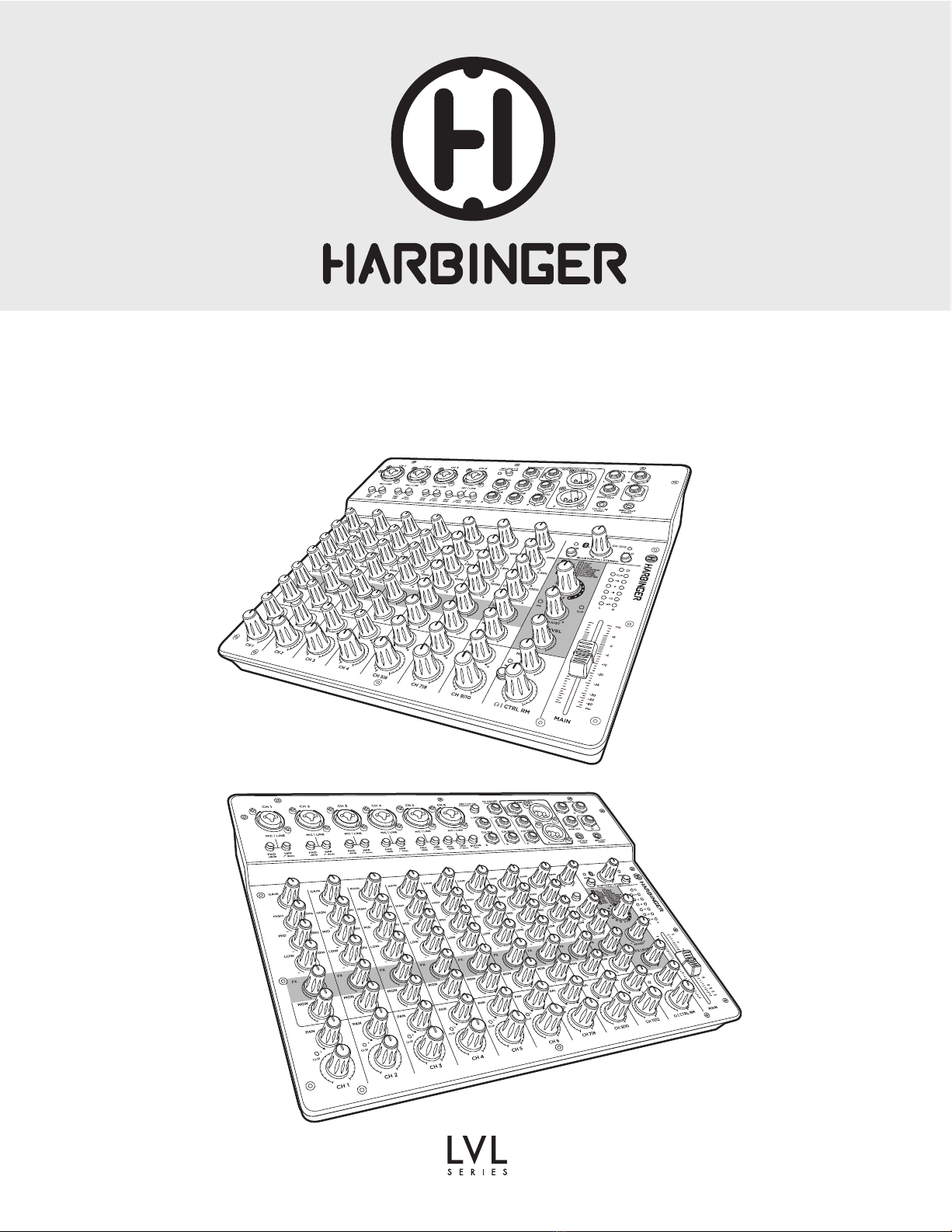
LV12 & LV14
OWNER’S MANUAL
LV12
LV 14

TABLE OF CONTENTS
Quick Start Guide: LV12 & LV14................................................................................... 4–5
Bluetooth Audio Input........................................................................................................ 5
LV12 Top Panel .............................................................................................................. 6–7
LV14 Top Panel ............................................................................................................. 8–9
LV12 & LV14 Rear Panel.................................................................................................. 10
LV14 Bluetooth Pairing, Troubleshooting........................................................................ 10
USB Walkthrough LV14.................................................................................................... 11
Appendix ................................................................................................................... 12–13
LV12 & LV14 Specifications...............................................................................................13
LV12 Block Diagram......................................................................................................... 14
LV14 Block Diagram ........................................................................................................ 15
Glossary of Terms..............................................................................................................16
Cable Diagrams................................................................................................................ 17
Important Safety Instructions ........................................................................................... 18
FCC Statements................................................................................................................. 19
Warranty/Customer Support.......................................................................................... 19

LV12 & LV14 OWNER’S MANUAL
3
WELCOME
Newly designed Harbinger LVL Series mixers offer premium-grade connection points, professional-level audio performance and convenient
Bluetooth® wireless audio connectivity. 4 available models cover everything from solo performances to full-band mixing, live and in studio, with our
LV12 and flagship LV14 that include USB recording and playback
LV12 - Compact 12-channel mixer with Bluetooth, 4 phantom power-
capable microphone preamps and digital FX
- Bluetooth®audio input with push-button Solo feature
- 4 High-headroom, low-noise microphone preamps
- Guitar input with Hi-Z switch for optimized impedance
- Built-in digital FX with Parameter Adjust for fine-tuning of FX presets
- 1/4” Monitor Output
- 48V Phantom Power for condenser microphones
- 4 XLR 1/4” combo inputs support a wide range of sources
- –26dB Pads and 80Hz High-Pass Filters minimize clipping and
low-frequency rumble
- XLR Main Outputs for connecting to pro-standard equipment
- 3-Band EQ for detailed tone adjustment
- Stereo ¼” Control Room Outputs
- 1/8” Stereo Input and Record Output for connecting to mobile
devices
- 1/4” Headphone Output
LV 14 - Compact 14-channel mixer with Bluetooth, 6 phantom power-
capable microphone preamps, digital FX and USB Audio
- Bluetooth® audio input with push-button Solo feature
- 6 High-headroom, low-noise microphone preamps
- Guitar input with Hi-Z switch for optimized impedance
- Built-in digital FX with Parameter Adjust for fine-tuning of FX presets
- 1/4” Monitor Output
- 48V Phantom Power for condenser microphones
- 6 XLR 1/4” combo inputs support a wide range of sources
- –26dB Pads and 80Hz High-Pass Filters minimize clipping and
low-frequency rumble
- XLR Main Outputs for connecting to pro-standard equipment
- 3-Band EQ for detailed tone adjustment
- USB audio connectivity for recording or playing tracks from PC
- Stereo ¼” Control Room Outputs
- 1/8” Stereo Input and Record Output for connecting to mobile
devices
- 1/4” Headphone Output

LV12 & LV14 OWNER’S MANUAL
4
QUICK START GUIDE: LVLV12 & LV14
CHECK KNOBS AND SWITCHES
• Turn all white-capped level knobs and MAIN level controls to the minimum (full counter-clockwise)
position. These are the CH 1 - CH 7|8 (LV12) and CH 1 - CH 11|12 (LV14) GAIN and level controls
and well as MAIN level controls
• Turn all grey-capped and blue-capped knobs to the 12 o’clock position. These are the PAN, BAL and
EQ controls
• Turn all green-capped level knobs to the minimum (full counter clockwise) position. These are the FX
level send controls. You can ignore the FX SELECT, FX ADJUST and FX LEVEL knobs in the FX section,
for now.
• All buttons should be in the up position. The white bottom edge of the button will be clearly visible
and 48V and SOLO LEDs should be off.
SETTING UP / HELPFUL TIPS
• Make sure the power switch is set to the off position
• Plug the included power supply into an AC power outlet and into the
power input on the rear panel of the mixer
INPUT CONNECTIONS
Choose any combination of the following sources:
• MICROPHONE - Connect a microphone to an XLR combo input jack
via XLR or 1/4” cable
• PHONE/TABLET/LAPTOP (ANALOG CONNECTION)- Connect a
tablet, phone or laptop to the CH 11|12 (LV12) or CH 13|14 (LV14)
STEREO input jack via stereo 3.5 mm TRS cable
• GUITAR/BASS - Connect a guitar or bass with a passive pickup to the
L (MONO) CH 3|4 (LV12) or L (MONO) CH 7|8 (LV14) input via
standard 1/4” guitar cable and press the GUITAR Hi-Z button
• COMPUTER (USB CONNECTION) - (LV14) Using a USB type “A”
to type “B” cable, connect the computer’s USB type “A” jack to the
mixer’s USB type “B” jack.
Headphones
Monitor Speakers
FX Section
Master Fader
Guitar/Bass
Microphone
Powered Speakers
Phantom Power
Off for dynamic
microphones, on for
condenser microphones
Laptop
Microphone connects here via XLR
mic cable
Phone/Tablet/Laptop

LV12 & LV14 OWNER’S MANUAL
5
BLUETOOTH®AUDIO INPUT
OUTPUT CONNECTIONS
• HEADPHONES – Connect a pair of headphones to the mixer’s 1/4”
headphone jack
•POWERED SPEAKERS – Connect the MAIN OUTS on the LV12 or LV14
to a pair of powered speakers via XLR cable
•MONITOR SPEAKERS – Connect the MON OUT on the LV12 or LV14
to a monitor speaker via a ¼” TRS cable
POWERING UP
• Power on any devices connected to input jacks
•Power on the LV12 or LV14
•Power on the powered speakers connected to the LV12 or LV14’s
MAIN OUTS
SETTING LEVELS
• MICROPHONE – If you have connected a condenser microphone, press the 48V switch (the 48V LED will come on). If you have connected a dynamic
microphone, the 48V switch should be in the off position with the 48V LED off. If you experience too much “boominess” or bass in the microphone signal,
set the 80Hz HPF button to the on position. While speaking or singing into the connected microphone, slowly bring up the channel 1 GAIN control until only
the loudest input briefly triggers the channel 1 CLIP indicator LED. Reduce the GAIN control slightly from this level. Continue speaking or singing into the
connected microphone and slowly bring up the CH 1 level control to the 12 o’clock position, then slowly bring up the MAIN level control until a comfortable
listening level is achieved.
• PHONE/TABLET/LAPTOP (ANALOG CONNECTION)– Press play on the connected audio player and increase the player’s internal volume control to
maximum level. Slowly bring up the BLUETOOTH | STEREO / CH 11|12 (LV12) / CH 13|14 (LV14) level control to the 12 o’clock position, then, slowly
bring up the MAIN level control until a comfortable listening level is achieved.
• GUITAR – Make sure the channel 5|6 (LV12) or channel 7|8 (LV14) GUITAR HI-Z switch is set to the on position. While strumming the guitar, bring up the
CH 5|6 channel level control (LV12) or CH 7|8 channel level control (LV14) to the 12 o’clock position and slowly bring up the MAIN level control until a
comfortable listening level is achieved.
• COMPUTER (USB CONNECTION) - (LV14) With the computer’s sound output set to WAVE OUT USB DEVICE and with audio playing on the computer,
press the CH 11|12 USB source selection button and bring up the CH 11|12 level control to the 12 o’clock position and slowly bring up the main level control
until a comfortable listening level is achieved.
• POWERED SPEAKERS – To monitor through powered speakers, while source signal from the microphone, phone/tablet/laptop, guitar or computer is
present, slowly bring up the MAIN fader level control until a comfortable listening level is achieved.
• MONITOR SPEAKERS – To monitor through a powered stage monitor or powered speaker connected to the MON OUT, slowly turn up (clockwise) the
MON level knob in the lower right corner of the mixer to the 12 o’ clock position and then turn up the MON send level on the channels you wish to send to
the connected monitor speaker.
• HEADPHONES – Since the headphone level control is independent from the MAIN level control, first ensure that the channel level controls are set so
that ample signal is feeding the main and headphone buses. The meters should show between +3 and +5 dB with the MAIN level control at the 12 o’clock
position (LV12) or 0 dB (LV14). When this is accomplished, slowly bring up the headphone level control until a comfortable listening level is achievedcontrols
are set so that ample signal is feeding the main and headphone buses. The meters should show between +3 and +5 dB with the MAIN level control at the 12
o’clock position. When this is accomplished, slowly bring up the headphone level control until a comfortable listening level is achieved.
The mixer powers up with Bluetooth off. Press the PAIR button to initialize Bluetooth and activate pairing (the PAIR LED will flash, indicating that it is ready to pair).
The LV12 or LV14 will automatically reconnect to the previous Bluetooth audio source if it is available, and will otherwise be available for Bluetooth pairing from a
source audio device such as a smartphone.
If connecting for the first time, look for and select “Harbinger Mixer” on your Bluetooth audio source device.
The PAIR LED is lit solid when currently paired, blinking when available for pairing, and off if Bluetooth has been disabled by pressing and holding the PAIR
button, or when the mixer first powers up.
Pressing the PAIR button when a pairing is active forces any currently connected Bluetooth audio source to disconnect, and makes the mixer available for pairing.
See Bluetooth Troubleshooting section in case of difficulty.
Connect the included
power supply here

LV12 & LV14 OWNER’S MANUAL
6
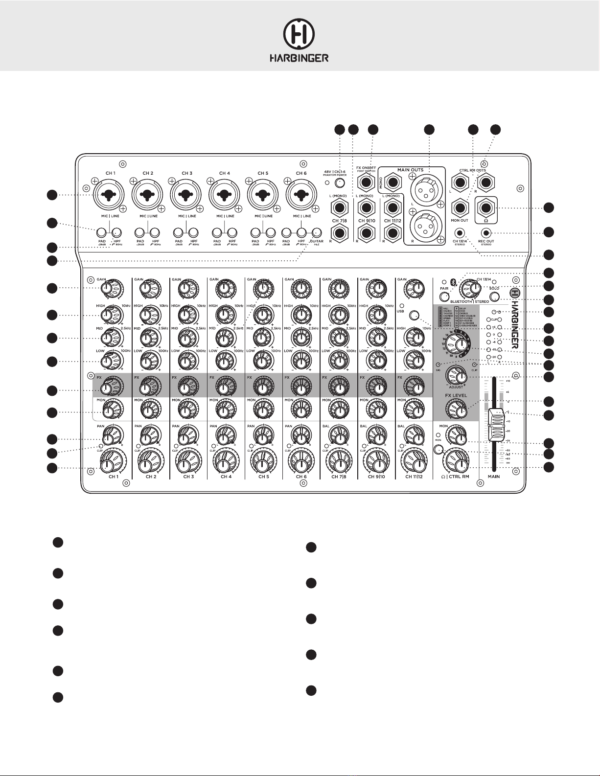
LV12 TOP PANEL
15 19
20
21
22
23
24
25
26
33
34
35
1
2
8
11
13
12
16
14 17
5
6
7
18
3
4
9
10
28
27
29
30
31
32

LV12 & LV14 OWNER’S MANUAL
7
1MIC /LINE INPUT
An XLR or 1/4” microphone or line level source can be connected here
2–26 dB PAD BUTTON
Reduces the signal strength of the associated input signal by 26 dB
380Hz HIGH-PASS FILTER
Reduces low frequency “rumble” from microphone signals
4GUITAR HI-Z BUTTON
Changes the impedance on CH4 to optimize passive guitar and bass
signals
5GAIN CONTROL
Adjusts the preamp gain for the associated channel
6HIGH EQ CONTROL
Boosts or cuts the high frequencies of the associated input signal, at a
corner frequency of 10 kHz
7MID EQ CONTROL
Boosts or cuts the mid frequencies of the associated input signal, at a
center frequency of 2.5 kHz
8LOW EQ CONTROL
Boosts or cuts the low frequencies of the associated input signal, at a
corner frequency of 100 Hz
9FX SEND CONTROL
Controls the relative level of the associated channel being sent to
the FX processor
10 MON SEND CONTROL
Controls the relative level of the associated channel being sent to the
MON OUT
11 PAN CONTROL
Adjusts positioning of the channel input signal within the stereo sound
field
12 CLIP INDICATOR LED
Lights red when the signal level at the preamp stage is too high and
causing clipping/distortion
13 CH LEVEL CONTROL
Adjusts the relative level of the associated channel being sent to the
MAIN bus
14 48V PHANTOM POWER BUTTON
Activates phantom power, which is required for condenser-type
microphones
15 1/4” INPUTS
CH5|6, CH7|8, CH9|10– Connect mono or stereo line-level signals here
16 FX ON|OFF FOOT SWITCH
Connect a ¼” single-button footswitch here to mute/unmute the internal
FX. This can be helpful when addressing the audience between songs
17 MAIN OUTPUTS
The signal at this output contains the entire mix of input signals. Connect
this output to the inputs of powered speakers, a power amp or recording
interface, via XLR cables. If a mono output is desired, connect a 1/4”
TRS cable to the MONO OUT jack.
18 CTRL RM OUTPUTS
¼” outputs for feeding control room speakers or studio monitors
19 MON OUTPUT
¼” mono output for feeding floor monitor speakers
20 HEADPHONE OUTPUT
Connect headphones here. This signal is the same as that being sent to
the MAIN bus
21 CH 11|12 STEREO INPUT
Connect a phone, tablet, or laptop here, with a stereo 1/8” (3.5 mm)
cable. This input is routed to the BLUETOOTH/CH 11|12 channel
22 REC OUT
This signal is taken from the MAIN bus. Connect this output to a
recording device with a stereo 1/8” (3.5 mm) input
23 BLUETOOTH PAIR BUTTON
With no actively paired device, pressing this button will activate pairing
mode (LED will start blinking)
With a device actively paired (LED lit solidly), pressing this button will
cancel the pair and will activate pairing mode (LED will begin blinking)
Pressing and holding this button will cancel any active pair and turn
Bluetooth off (LED will turn off)
24 BLUETOOTH |CH 11|12 STEREO LEVEL CONTROL
Controls the level of the BLUETOOTH and CH 11|12 input signals being
sent to the MAIN bus
25 BLUETOOTH
| CH 11|12 SOLO BUTTON
Mutes all input sources except BLUETOOTH or CH 11|12 input signals
26 POWER LED
When the LV12 is powered on this LED will be lit red
27 MAIN OUTPUT LEVEL METERS
Display the main mix output level
28 FX PRESET CONTROL AND LISTING
Selects the FX preset 1–16. The FX type for each preset can be seen in
the list above the knob.
29 FX SIG & CLIP LEDs
These LEDs light up to give information about the incoming signal to the FX
processor. When there is signal present, the SIG LED will be lit, indicating
there is audio passing through the FX processor. If the CLIP LED is lit at any
time, the incoming audio is distorting and the resulting FX will also be distorted
30 FX ADJUST CONTROL
This control changes the characteristics of the selected FX preset
parameters allowing you to customize each preset
31 FX LEVEL CONTROL
This control adjusts the overall level of the effected signal from the FX
processor that is being sent to the MAIN OUTPUTS
32 MAIN OUTPUT LEVEL FADER CONTROL
This fader controls the level of the MAIN OUTPUT
33 MON MASTER CONTROL
Controls the combined send output level feeding the MON OUTPUT
34 MON SEND TO PHONES | CTRL RM
When pressed, the MON send is sent to the Headphone and CTRL RM
OUTPUTS. When up, the Phones and CTRL RM OUTPUTS are the same
as the MAIN OUTPUTS
35 HEADPHONE|CTRL RM MASTER CONTROL
This control adjusts the signal level feeding the CTRL RM OUTS and the
Headphone output
LV12 & LV14 OWNER’S MANUAL
8
16 17 18 19
20
22
29
28
24
25
26
23
30
31
33
34
35
36
LV14 TOP PANEL
1
2
3
4
5
9
1514
6
7
8
10
11
12
13
21
27
32
1MIC /LINE INPUT
An XLR or 1/4” microphone or line level source can be connected here
2–26 dB PAD BUTTON
Reduces the signal strength of the associated input signal by 26 dB
380Hz HIGH-PASS FILTER
Reduces low frequency “rumble” from microphone signals
4GUITAR HI-Z BUTTON
Changes the impedance on CH6 to optimize passive guitar and bass
signals
5GAIN CONTROL
Adjusts the preamp gain for the associated channel
6HIGH EQ CONTROL
Boosts or cuts the high frequencies of the associated input signal, at a
corner frequency of 10 kHz
7MID EQ CONTROL
Boosts or cuts the mid frequencies of the associated input signal, at a
center frequency of 2.5 kHz
8LOW EQ CONTROL
Boosts or cuts the low frequencies of the associated input signal, at a
corner frequency of 100 Hz
9FX SEND CONTROL
Controls the relative level of the associated channel being sent to the
FX processor
10 MON SEND CONTROL
Controls the relative level of the associated channel being sent to the
MON OUT
11 PAN CONTROL
Adjusts positioning of the channel input signal within the stereo sound
field

LV12 & LV14 OWNER’S MANUAL
9
12 CLIP INDICATOR LED
Lights red when the signal level at the preamp stage is too high and
causing clipping/distortion
13 CH LEVEL CONTROL
Adjusts the relative level of the associated channel being sent to the
MAIN bus
14 48V PHANTOM POWER BUTTON
Activates phantom power, which is required for condenser-type
microphones
15 1/4” INPUTS
CH7|8, CH9|10, CH11|12– Connect mono or stereo line-level signals here
16 FX ON | OFF FOOT SWITCH
Connect a ¼” single-button footswitch here to mute/unmute the internal
FX. This can be helpful when addressing the audience between songs
17 MAIN OUTPUTS
The signal at this output contains the entire mix of input signals. Connect
this output to the inputs of powered speakers, a power amp or recording
interface, via XLR cables. If a mono output is desired, connect a 1/4”
TRS cable to the MONO OUT jack.
18 CTRL RM OUTPUTS
¼” outputs for feeding control room speakers or studio monitors
19 MON OUTPUT
¼” mono output for feeding floor monitor speakers
20 HEADPHONE OUTPUT
Connect headphones here. This signal is the same as that being sent to
the MAIN bus
21 REC OUT
This signal is taken from the MAIN bus. Connect this output to a
recording device with a stereo 1/8” (3.5 mm) input
22 CH 13|14 STEREO INPUT
Connect a phone, tablet, or laptop here, with a stereo 1/8” (3.5 mm)
cable. This input is routed to the BLUETOOTH/ CH 13|14 channel
23 BLUETOOTH PAIR BUTTON
With no actively paired device, pressing this button will activate pairing
mode (LED will start blinking)
With a device actively paired (LED lit solidly), pressing this button will
cancel the pair and will activate pairing mode (LED will begin blinking
Pressing and holding this button will cancel any active pair and turn
Bluetooth off (LED will turn off)
24 BLUETOOTH / CH 13|14 STEREO INPUT LEVEL CONTROLS
Controls the level of the BLUETOOTH and CH 13|14 input signals being
sent to the MAIN bus
25 BLUETOOTH / CH 13|14 SOLO BUTTON
Mutes all input sources except BLUETOOTH or CH 13|14 input
26 POWER LED
When the LV14 is powered on this LED will be lit red.
27 USB ROUTING TO CH11|12 BUTTON
Pressing this button routes the USB audio input to CH 11|12. Use the CH
11|12 level control to send this signal to the MAIN mix. If you are recording
over existing tracks coming from a DAW and you wish to exclude those
tracks from the audio being recorded, reduce the CH 11|12 level control to
its minimum / full counter-clockwise position (do this for any channels you
do not want recorded by the DAW). Press the MON SEND to PHONES |
CONTROL ROOM button and use the channel MON SEND CONTROLS
to create a mix of the playback and live recording tracks. You will hear both
the playback tracks and the signals you are recording, but only the signals
being sent to the MAIN mix will be recorded by the DAW
28 MAIN OUTPUT LEVEL METERS
Display the main mix output level
29 FX PRESET CONTROL AND LISTING
Selects the FX preset 1–16. The FX type for each preset can be seen in
the list above the knob
30 FX SIG AND CLIP LEDs
These LEDs light up to give information about the incoming signal to
the FX processor. When there is signal present, the SIG LED will be lit,
indicating there is audio passing through the FX processor. If the CLIP LED
is lit at any time, the incoming audio is distorting and the resulting FX will
also be distorted
31 FX ADJUST CONTROL
This control changes the characteristics of the selected FX preset
parameters allowing you to customize each preset
32 FX LEVEL CONTROL
This control adjusts the overall level of the effected signal from the FX
processor that is being sent to the MAIN OUTPUTS
33 MAIN OUTPUT LEVEL FADER CONTROL
This fader controls the level of the MAIN OUTPUT
34 MON MASTER CONTROL
Controls the combined send output level feeding the MON OUTPUT
35 MON SEND TO PHONES | CTRL RM
When pressed, the MON send is sent to the Headphone and CTRL RM
OUTPUTS. When up, the Phones and CTRL RM OUTPUTS are the same
as the MAIN OUTPUTS
36 HEADPHONE|CTRL RM MASTER CONTROL
This control adjusts the signal level feeding the CTRL RM OUTS and the
Headphone output
35 10
LV12 & LV14 OWNER’S MANUAL
10
BLUETOOTH®PAIRING, TROUBLESHOOTING
LED STATE AND BLUETOOTH STATUS
LED is Off - Bluetooth is off
LED is Blinking - Bluetooth is ready to pair
LED is solidly lit - Bluetooth is actively paired with a source device
If the pair LED is in an off state, press the mixer’s BLUETOOTH PAIR button to
initialize Bluetooth and activate pairing mode (the pair LED will start blinking).
Scan for available Bluetooth devices on your phone, tablet or PC. Locate and
select “Harbinger Mixer” to activate pairing. When actively paired, the mixer’s
pair LED will become solidly lit.
If another device is already actively paired press the PAIR button to clear
the active pairing.
Pressing and holding PAIR disables Bluetooth.
• On your Apple iOS device
1. Power off the mixer and leave it off. Open Settings app,
select Bluetooth
2. Open Settings app, select Bluetooth
3. If “Harbinger Mixer” is listed under MY DEVICES, touch info
button,
tap to Forget This Device
4. Turn off Bluetooth, wait 10 seconds, turn on Bluetooth
• On your Android device
1. Power off the mixer and leave it off
2. Open Settings, select Bluetooth
3. If “Harbinger Mixer” is listed under Paired Devices, touch gear
Icon, and tap to Un-pair
4. Turn off Bluetooth, wait 10 seconds, turn on Bluetooth
• Then power on your mixer and press PAIR (the pair LED should flash)
• You should now be able to connect to mixer via Bluetooth
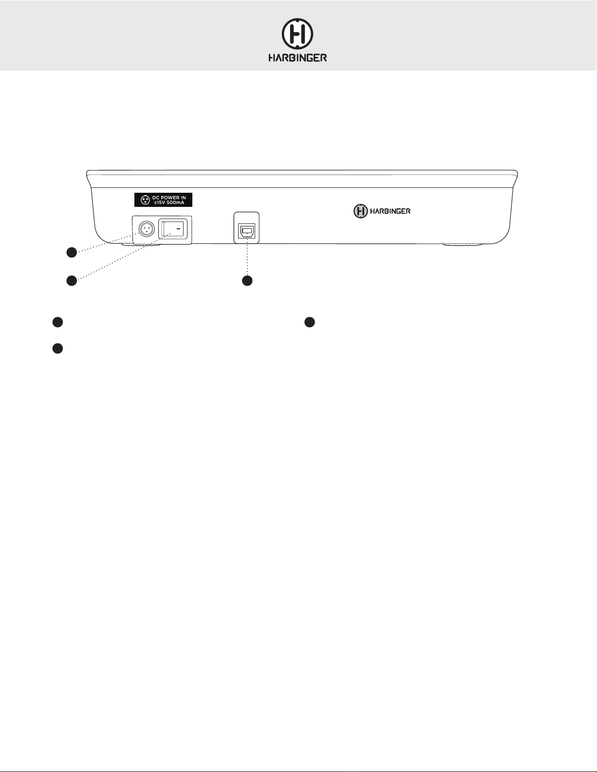
LV14 REAR PANEL
1DC POWER INPUT
Connect only the included power adapter to this input
2POWER SWITCH
Switches power on/off to the mixer
3USB PORT
Connect a standard USB cable from the mixer to a MAC or PC in order
to record and playback audio from a connected computer
1
2
These steps should resolve any Bluetooth trouble you may encounter:
3

LV12 & LV14 OWNER’S MANUAL
11
USB WALKTHROUGH LV14
PLAYBACK & RECORDING VIA USB
The LV14 is fully ASIO (Windows) and Core Audio (MAC) compliant audio interface and as such does not require any special driver installation.
Playback:
1. Make sure the LV14 mixer - WAVE OUT USB DEVICE is set as the audio output device within the PC’s system settings and within the DAW software
or audio player
2. Start audio playback from the DAW or audio player
3. Press the USB ROUTING TO CH 11 |12 BUTTON
4. MON SEND TO PHONES | CTRL RM button is in the up position
5. Slowly bring up the CH11|12 level control
Recording:
1. Connect all input signals to the LV14 mixer
2. Set the channel level controls and MAIN level fader so that the MAIN level meters show the mix peaking somewhere around 0 dB
3. Make sure the LV14 mixer - WAVE OUT USB DEVICE is selected as the audio input device within the PC’s system settings and within the DAW software
4. Arm the stereo DAW track and press record. The mixer’s MAIN MIX will now be recorded by the DAW
NOTE: The stereo MAIN mix output signal is the default signal feeding the USB audio output and being sent to the DAW. Playback audio from the DAW will
route to the LV14’s CH 11|12 (when the USB ROUTING TO CH 11|12 button is engaged on the LV14).
Overdubbing:
1. Make sure the LV14 mixer - WAVE OUT USB DEVICE is set as the audio input and output device within the PC’s system settings and within the DAW software
2. Reduce the LV14’s CH 11|12 level control to its minimum / full counter-clockwise position (do this for any channels you do not want recorded by the DAW)
3. While singing/strumming/drumming, bring up the channel level controls for the channels you are about to record, and watch the input level meters on your
DAW to make sure the loudest parts of the input are just below clipping.. Any signal panned hard-left will be sent out the left channel only, any channel
panned hard-right will be sent out the right channel only.
is in MON position and use the channel MON SEND CONTROLS to create a
mix of the playback and live recording tracks. You will hear both the playback tracks and the signals you are recording in the Headphones and CTRL RM
OUTS, but only the signals being sent to the MAIN mix will be recorded by the DAW.
5. Within the DAW, you will have the option to record a mono signal (splitting the L + R MAIN MIX into separate tracks) or a stereo signal. Select the
appropriate input within the DAW. Arm the DAW track and hit record.
A REAL-WORLD EXAMPLE USING THE LV14:
Tracking a Vocal and a Guitar simultaneously to a click track being generated by your DAW.
1. Within the DAW, initialize 2 separate mono tracks that will serve as destinations for the vocal and guitar signals coming from the mixer. On the vocal channel,
select the mixer’s R output, on the guitar channel, select the mixer’s L output.
2. Plug your vocal mic into XLR or TRS input of CH1 (activating the 48V Phantom Power switch if it is a condenser mic)
3. While watching the mixer’s CH1 clip indicator, sing into the microphone and set the CH1 GAIN control so that only the loudest input causes brief clipping.
Then reduce the gain slightly.
4. While watching the input level meter of the DAW’s vocal channel, adjust the mixer’s CH1 LEVEL control to get an acceptable level feeding the DAW.
The loudest input should fall just below clipping.
5. Then turn the CH1 PAN control all the way to the right
6. Plug your guitar into CH 7|8 L/mono input and engage the Hi-Z button.
7. While watching the CH 7|8 clip indicator LED, strum the guitar. When only the loudest input briefly triggers the clip LED, reduce the CH 7|8 GAIN
control slightly.
8. While watching the input level meters of the DAW’s guitar channel input, strum the guitar and bring up the mixer’s CH 7|8 LEVEL control until the loudest
input falls just below clipping.
9. Now turn the Pan control on CH 7|8 all the way to the left
10. Your DAW or audio capture software can now receive the vocal channel audio and the guitar channel audio on 2 separate tracks. Keep in mind, if the
microphone is in close proximity to the guitar, there will likely be some bleed of the guitar into the vocal channel.
11. Now in your DAW set up a channel that can play a click or guide track at the desired tempo, but do not start playing it yet
12. Set up your DAW’s audio output to WAVE OUT USB DEVICE and on the mixer press the USB Routing to CH 11|12 button
13. Set the HEADPHONE|CTRL RM SOURCE button to the MON position
14. Make sure the CH 11|12 level control is turned all the way down to the left (counter-clockwise) and slowly turn up the MON level control on CH 11|12.
15. Use the channel MON SEND CONTROLS to create a mix of the playback and live recording tracks. You will hear both the playback tracks and the signals
you are recording in the Headphones and CTRL RM OUT output, but only the signals being sent to the MAIN mix will be recorded by the DAW
16. Now when you arm a channel and hit record in your DAW, the click or guide track audio will be sent to the LV14 for you to monitor in headphones or
control room speakers, but your final captured performance will not include these signals. Only your performance will be captured via USB into your DAW.
27
35
27
10
4. On LV14, make sure the MON SEND to PHONES | CTRL RM button 35
LV12 & LV14 OWNER’S MANUAL
12
MICROPHONE INPUT (MIC)
This XLR combo connector will accept virtually any professional
microphone. It is designed for microphone and line level signals on either
XLR
or ¼” cables.
Some microphones, mostly condenser mics, need phantom power to
operate. Switch on 48V phantom power. If you’re unsure if your mic needs
phantom power, check the instructions or the manufacturer’s website for
information. Phantom power should not hurt most microphones, except for
very old or damaged ribbon microphones.
For live microphone use (where the microphone signal is amplified through
a PA system) engaging the HPF (high-pass filter) is recommended for
reducing “boominess” and maintaining clarity in the microphone signal.
Use the microphone preamp’s gain control (explained below) to bring the
microphone up to a high enough level to use with the mixer.
LINE INPUT (LINE)
This ¼” input is designed for line-level signals. It accepts either balanced
(TRS) or unbalanced (TS) cables. The level of this input is also controlled
by the gain control, explained below.
Do not use both the microphone and line inputs on the same channel.
The mixer will distort and the noise level will go up.
The line input is not designed to accept an instrument-level signal, such as
the output from an electric or acoustic guitar or bass. If you want to plug
your instrument into the mixer, we suggest a direct box (also called a DI
box). Plug your instrument into the direct box, then plug the output of the
direct box into the microphone input of the mixer.
GUITAR/BASS
Passive guitar or bass signals tend to have the best sound and sensitivity
when they are connected to a high-impedance input (similar to what you
would find on a guitar or bass amp). When connecting a passive guitar
or bass signal to CH 3|4, engaging the GUITAR HI-Z switch is
recommended. It is possible to connect 2 guitar signals to CH 3|4
simultaneously. When both inputs are used, the signals will be hard-
panned left and right. If you wish to have both guitars panned to the
center so that they project from both speakers in PA setup, press the
MONO button next to the MAIN level control.
If connecting an active acoustic guitar signal to CH 1 or CH 2, engaging
the
HPF is recommended for rolling-off “boominess”.
GAIN
Gain controls the level of the microphone or line level signal plugged into
the mixer. If the gain is set too low, the output signal will be noisy when you
turn it up at the level control. If gain is set too high, it will distort.
For best performance, set the gain while looking at the meters. Turn the
Level control so that it’s facing straight up. Then turn the gain up until you
see the first or second lights on the meters. Don’t set it too high – although
you might not hear distortion when playing by itself, when all of the
channels are playing at that level they may add together and distort the
mixer.
Sidebar: “Why are there two volume controls?”
The Gain and Level controls work together to get the best performance out
of the mixer. A quiet signal may need more gain than a loud guitar amp
going into a sensitive microphone. Set the gain so that the level on each
channel is roughly the same, then use the Level controls to set the balance
that you want in your mix.
GAIN STAGING
Gain staging involves setting the serial amplification stages of an audio
signal in a way that achieves best signal to noise ratio. Improper gain
staging can result in more background noise, less clarity and lower sound
system efficiency. If your mixer is connected to a FOH amplifier or powered
speakers, you will need to first set the level of these for an appropriate
audience listening level. To set your FOH amplifier or powered speaker
level, connect a full-range line level music source to your mixer and set
the peak level on the channel meters somewhere between -6dB and
0dB. Set your main output level to zero/unity and slowly bring up the
amplifier or powered speaker levels to a volume that makes sense for the
venue. With this main output level set, you can move on to setting levels
for the individual inputs. Start with gain and channel level controls at their
minimum positions. For microphone signals, while speaking or singing
into the connected microphone, slowly bring up the channel GAIN control
until only the loudest input briefly triggers the channel CLIP indicator LED.
Reduce the GAIN control slightly from this level. With the main output level
control set to zero/unity, continue speaking or singing into the connected
microphone and slowly bring up the channel LEVEL to a desired listening
level. Follow this process for any microphone signals. When setting relative
levels between channels, best practice is to reduce levels of signals that are
too loud, working subtractively.
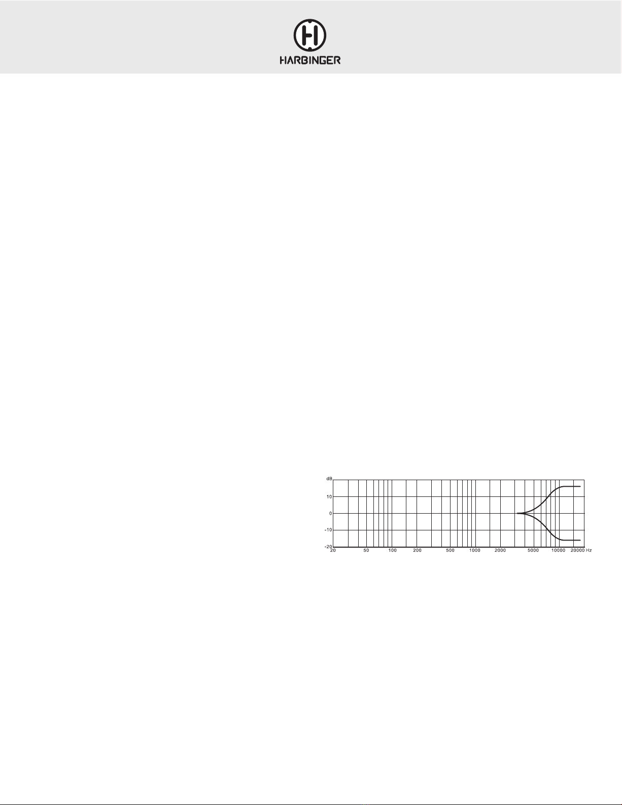
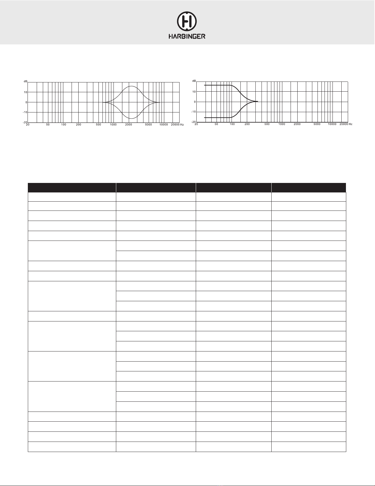
The high EQ control is a shelving EQ. What this means is that it boosts or
cuts from 10kHz and everything above that. Turn it up to bring out the
breath of a vocal or the high overtones of the cymbals. Turn it down to
reduce finger squeaks on a guitar or bass.
The high EQ control is a shelving EQ. What this means is that it
boosts or cuts from 12kHz and everything above that. Turn it up to
bring out the breath of a vocal or the high overtones of the cymbals.
Turn it down to reduce finger squeaks on a guitar or bass.
EQ HI
EQ LOW
RELATIVE RESPONSE IN dB
FREQUENCY IN HZ
FREQUENCY RESPONSE
RELATIVE RESPONSE IN dB
FREQUENCY IN HZ
FREQUENCY RESPONSE
APPENDIX
LV12 & LV14 OWNER’S MANUAL
13
Parameter Condition LV12 LV 14
Frequency Response Mic In to Main Out (Trim at 0 db) 20 Hz – 22 kHz 20 Hz – 22 kHz
THD Mic In to Main Out (20Hz to 20 kHz) 0.009% 0.009%
Preamp Noise (EIN) 20 Hz to 20 kHz, (150 ohm sources) –121dB –121dB
Residual Output Noise All level controls @ minimum –91dB –91dB
Common Mode Rejection Ratio (CMRR) Maximum Gain >68dB @ 1 kHz >68dB @ 1 kHz
Crosstalk
Adjacent Channels –88dB –88dB
Same channel (stereo separation) –82dB –82dB
Input Gain Control Range +15dB to +63 dB +15dB to +63 dB
Phantom Power DC +/–48V +/–48V
Equalization
Mono Channel, High ±12dB@ 10 kHz ±12dB@ 10 kHz
Mono Channel, Mid ±15dB@ 2.5 kHz ±15dB@ 2.5 kHz
Mono Channel, Low ±12dB@ 100Hz ±12dB@ 100Hz
Output Level Maximum +22 dBu +22 dBu
Maximum Input Levels
Mic +6dBu (with –26dB PAD) +6dBu (with –26dB PAD)
Line Input +21dBu at Unity Gain +21dBu at Unity Gain
Aux Input +6dBu at +15dB Level max +6dBu at +15dB Level max
Input Impedance
Mic 2kΩ, balanced 2kΩ, balanced
Line Input 10kΩ, balanced 10kΩ, balanced
Aux Input 10kΩ, balanced 10kΩ, balanced
Output Impedance
Main 120Ω 120Ω
Control Room, Rec Out 120Ω 120Ω
Headphones 100Ω 100Ω
VU Meters 4 Segments Clip (+16), +6, 0, –6, –10, –20dB Clip (+16), +6, 0, –6, –10, –20dB
AC Power Requirements 3-pin mini XLR connector ±15VDC @ 500 mA ±15VDC @ 500 mA
Dimensions L x W x H (shown in Inches) 10.71”L x 9.65”W x 2.40”H 12.91”L x 9.65”W x 2.40”H
Weight (net) Without PSU 2.97 lbs 4.03 lbs
LV12 & LV14 SPECIFICATIONS
The mid EQ is a peaking EQ, centered at 2.5kHz. This boosts or cuts
the high midrange of your signal. You might turn it up if your vocal
isn’t cutting through the mix, or turn it down if a percussion part is
too harsh.
This low EQ boosts or cuts everything from 100Hz or below. You might
bring it up for more bottom out of your kick or bass guitar, and turn it down
to reduce rumble from a vocal or wind instrument.
EQ HI
EQ LOW
RELATIVE RESPONSE IN dB
FREQUENCY IN HZ
FREQUENCY RESPONSE
RELATIVE RESPONSE IN dB
FREQUENCY IN HZ
FREQUENCY RESPONSE
EQ MID
FREQUENCY IN HZ
FREQUENCY RESPONSE
REL
A
TIVE RESPONSE IN
dB

LV12 & LV14 OWNER’S MANUAL
14
LV12 BLOCK DIAGRAM

LV12 & LV14 OWNER’S MANUAL
15
LV14 BLOCK DIAGRAM

LV12 & LV14 OWNER’S MANUAL
16
GLOSSARY OF TERMS
BALANCED
A 3-conductor (including shield), low-impedance connection. Balanced
cables are the preferred method for hum-free interconnection of a sound
system for their noise-rejection characteristics.
(Also see Unbalanced.)
BUSS
An output destination in a mixer. For example, the left and right main
outputs are called busses, because you can send a channel to one or both
of them. Also spelled Bus
CHANNEL
One of any number of signal paths in an audio circuit, such as input
channel, output channel, recording channel, left channel, right channel, etc.
DECIBEL (DB)
A term representing the ratio between different audio levels. It can either
refer to the electrical signal running through a channel or the acoustic
sound level coming from a sound source.
EQUALIZATION
Electronic filters that adjust the level of certain frequencies. Used for tone
enhancement or to reduce extraneous sounds. Two types of EQ shapes are
Peak and Shelving, described below.
HI-Z (HIGH IMPEDANCE)
In the audio equipment realm, the term “Hi-Z” or “High-Impedance”
generally refers to inputs designed for passive guitar or bass signals (1MΩ
or thereabouts).
HPF (HIGH-PASS FILTER)
An electronic filter that passes signals with a frequency higher than a
specific cutoff frequency and attenuates signals with frequencies lower than
the cutoff frequency.
IMPEDANCE
Resistance in an electrical circuit measured in Ohms (Ω). Maintaining
proper impedance (between amplifier and speakers for example) is
important to prevent damage to the amp.
48V PHANTOM POWER
A voltage signal that runs through a microphone cable to power condenser
microphones. Harmless to microphones that don’t need it, except for very
old and/or damaged ribbon microphones.
SHELVING EQUALIZER CONTROL
Increase or decrease of all frequencies above or below a specific point.
(Compare to Peak Equalizer Control; see pages 8-9 for more information.)
TRS
Acronym for Tip-Ring-Sleeve — the three parts of a three-conductor
(including shield) audio plug. TRS phone plugs are often used for
“balanced” mono connections, or stereo “unbalanced” (head-phone)
connections.
TS
Acronym for Tip-Sleeve, the two parts of an unbalanced, two-conductor
(including shield) phone plug. TS connectors are some-times called mono
or unbalanced plugs or jacks.
UNBALANCED
A two-conductor (including shield), high-impedance connection. These are
most commonly used for instrument connections and cable runs of less than
20 feet.
XLR
The three-pin connector universally used for balanced audio connections. A
balanced connection reduces outside noise and interference.
(See Balanced above.)
LV12 & LV14 OWNER’S MANUAL
17
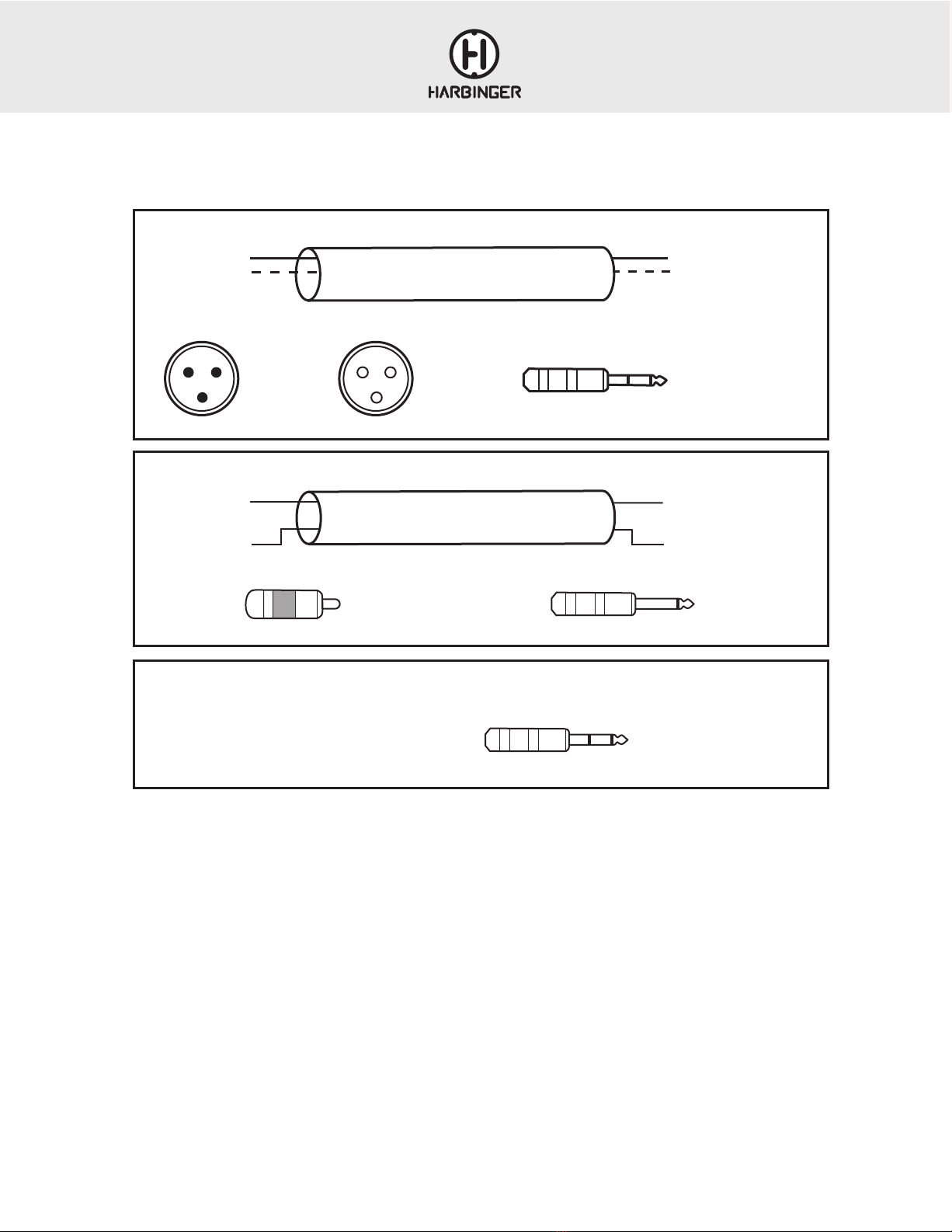
CABLE DIAGRAMS
BALANCED CABLE
UNBALANCED CABLE
UNBALANCED STEREO
T: Positive Left T
TSRCA
RS
R: Negative Right
S: Shield
1. Center
2. Shield
2
S - Shield
+ Positive
+ Positive
– Negative
S - Shield
+ Positive
S - Shield
1. Shield
2. Positive
3. Negative
T Positive
R Negative
S-Shield
XLR-M
TRS
XLR-F
S R
+ Positive
– Negative
S - Shield
1
2
3
2
1
3
T

LV12 & LV14 OWNER’S MANUAL
18
IMPORTANT SAFETY INSTRUCTIONS
Please keep this instruction manual for future reference and for the duration of owning
the owning the LV12 or LV14 mixers. Please carefully read and understand the
instructions inside this owner’s manual before attempting to operate your new mixer.
This instruction manual includes essential safety information regarding the use and
maintenance of the mixer. Take special care to heed all warning symbols and signs
inside this manual and those printed on the bottom of the mixer.
WARNING
TO PREVENT FIRE OR SHOCK HAZARD, DO NOT EXPOSE THE PRODUCT TO
WATER/MOISTURE, NOR SHOULD YOU OPERATE THE PRODUCT NEAR ANY
WATER SOURCE.
The exclamation point triangular symbol is intended to alert the user to the presence
of important operating and maintenance(servicing) instructions in the user manual
accompanying the product.
The lightning flash with an arrow triangular symbol is intended to alert
the user to the presence of non-insulated “dangerous voltage” within the
product’s enclosure, and may be of sufficient magnitude to constitute a risk of
electric shock.
WARNING
Handle the power supply cord with care.
Do not damage or deform it as it may cause electric shock or malfunction when used.
Hold the plug attachment when removing from wall outlet. Do not pull on the power cord.
IMPORTANT SAFETY PRECAUTIONS
1. READ INSTRUCTIONS – All the safety and operating instructions should be read
before this product is operated.
2. RETAIN INSTRUCTIONS – The safety and operating instructions should be retained
for future reference.
3. HEED WARNINGS – All warnings on the product and in the operating
instructions should be adhered to.
4. FOLLOW INSTRUCTIONS – All operating and use instructions should be followed.
5. DO NOT turn on the product module before connecting all other
external devices.
6. WATER AND MOISTURE – Moisture can damage the product and can cause
corrosion of electrical contacts. The system should not be used near water - for
example, a bathtub, washbowl, kitchen sink, laundry tub, wet basement, or near a
swimming pool, and the like.
7. HEAT – The product should be situated away from heat sources such as radiators,
heat registers, stoves, or other sources (including amplifiers) that produce heat.
8. POWER SOURCES – This product should be operated only from the type of power
source indicated on the rating label. If you are not sure of the type of power supply
to your home, consult your product dealer or local power company.
9. GROUNDING OR POLARIZATION – Do not defeat the safety purpose of the
polarization or grounding-type plug. The wide blade or the third prong is provided
for your safety. If the provided plug does not fit your outlet, consult an electrician for
replacement of the obsolete outlet. Do not defeat the safety purpose of the 3rd pin
grounding prong.
10. POWER-CORD PROTECTION – Power supply cords should be routed so
that they are not likely to be walked on or pinched by items placed upon
or against them, paying particular attention to the cord in correspondence
of plugs, convenience receptacles, and the point where they exit from
the product.
11. CLEANING – The product should be cleaned only as recommended by the
manufacturer. Clean by wiping with a dry cloth. Avoid getting water inside the
product.
12. NON-USE PERIODS – The power cord of the product should be unplugged from
the outlet when left unused for a long period of time.
13. OBJECT AND LIQUID ENTRY – Care should be taken so that objects do not fall and
liquids are not spilled into the enclosure through openings.
14. DAMAGE REQUIRING SERVICE – The product should be serviced by qualified
service personnel when:
A. The power supply cord or the plug has been damaged; or
B. Objects have fallen, or liquid has been spilled into the product; or
C. The product has been exposed to rain; or
D. The product does not appear to operate normally or exhibits a marked change
in performance; or
E. The product has been dropped, or the enclosure damaged.
15. Keep the product out of extended or intense direct sun light. 16. No containers
filled with any type of liquid should be placed on or near
the product.
17. SERVICING – The user should not attempt any service to the product beyond that
described in the operating instructions. All other servicing should be referred to
qualified service personnel.
18. VENTILATION – Slots and openings in the product are provided for ventilation
and to ensure reliable operation of the product and to protect it from overheating.
These openings must not be blocked or covered. The openings should never be
blocked by placing the product on a bed, sofa, rug, or other similar surface. This
product should not be placed in a built-in installation such as a bookcase or rack.
19. ATTACHMENTS – do not use attachments not recommended by the product
manufacturer, as they may cause hazards.
20. ACCESSORIES – Do not place this product on an unstable cart, stand, tripod,
bracket, or table. The product may fall, causing serious injury to a child or adult,
and serious damage to the product. Use only with a cart, stand, tripod, bracket, or
table recommended by the manufacturer, or sold with the product.
21. LIGHTNING – For added protection during a lightning storm, or when it is left
unattended and unused for long periods of time, unplug it from the wall outlet. This
will prevent damage to the product due to lightning and power-line surges.
22. REPLACEMENT PARTS – When replacement parts are required,
be sure the service technician has used replacement parts specified by the
manufacturer or have the same characteristics as the original part. Unauthorized
substitutions may result in fire, electric shock, or
other hazards.
23. SAFETY CHECK – Upon completion of any service or repairs to this product, ask
to perform safety checks to determine that the product is in the service technician
to perform safety checks to determine that the product is in proper operating
condition.
To prevent electric shock, or other outlet unless the do not use a polarized plug with an
extension cord, receptacle blades can be fully inserted to prevent blade exposure.
WARNING: To reduce the risk of fire or shock do
not expose this equipment to rain or moisture.
AVERTISEEMENT: Pour réduire les risques
d’incendie et d’électrocution, ne pas exposer ce
matérial à la pluie ou à l’humidité.
RISK OF
ELECTRIC SHOCK
DO NOT OPEN
RISQUE DE CHOC
ELECTRIQUE NE
PAS OUVRIR
RISK OF
ELECTRIC SHOCK
DO NOT OPEN
RISQUE DE CHOC
ELECTRIQUE NE
PAS OUVRIR
CAUTION: To reduce the risk of electric shock, do not
remove chassis. No user-serviceable parts inside.
Refer servicing to qualified service personnel.
AVERTISEEMENT: Pour réduire les risques d’incendie et
d’électrocution, ne pas exposer ce matérial à la pluie ou
à l’humidité.
THIS SYMBOL IS INTENDED TO ALERT THE USER TO THE
PRESENCE OF IMPORTANT OPERATING AND MAINTENANCE
(SERVICING) INSTRUCTIONS IN THE LITERATURE
ACCOMPANYING THE UNIT.
WARNING: To reduce the risk of fire or shock do
not expose this equipment to rain or moisture.
AVERTISEEMENT: Pour réduire les risques
d’incendie et d’électrocution, ne pas exposer ce
matérial à la pluie ou à l’humidité.
RISK OF
ELECTRIC SHOCK
DO NOT OPEN
RISQUE DE CHOC
ELECTRIQUE NE
PAS OUVRIR
RISK OF
ELECTRIC SHOCK
DO NOT OPEN
RISQUE DE CHOC
ELECTRIQUE NE
PAS OUVRIR
CAUTION: To reduce the risk of electric shock, do not
remove chassis. No user-serviceable parts inside.
Refer servicing to qualified service personnel.
AVERTISEEMENT: Pour réduire les risques d’incendie et
d’électrocution, ne pas exposer ce matérial à la pluie ou
à l’humidité.
APPARATUS SHALL NOT BE EXPOSED TO DRIPPING OR
SPLASHING AND THAT NO OBJECTS FILLED WITH LIQUIDS,
SUCH AS VASES, SHALL BE PLACED ON THE APPARATUS.

LV12 & LV14 OWNER’S MANUAL
19
FCC STATEMENTS
1. Caution: Changes or modifications to this unit not expressly approved by
the party responsible for compliance could void the user’s authority to
operate the equipment.
2. Note: This equipment has been tested and found to comply with the limits
for a Class B digital device, pursuant to Part 15 of the FCC Rules. These
limits are designed to provide reasonable protection against harmful
interference in a residential installation. This equipment generate, uses,
and can radiate radio frequency energy and , in not installed and used in
accordance with the instructions, may cause harmful interference to radio
communications. However, there is no guarantee that interference will
not occur in a particular installation. If this equipment does cause harmful
interference to radio or television reception, which can be determined by
turning the equipment off and on, the user is encouraged to try to correct
the interference by one or more of the following measures:
• Reorient or relocate the receiving antenna
• Increase the separation between the equipment and receiver
• Connect the equipment into an outlet on a circuit different from that to
which the receiver is connected
• Consult the dealer or an experienced radio/TV technician for help
WARRANTY/CUSTOMER SUPPORT
2 YEAR HARBINGER LIMITED WARRANTY
Harbinger provides, to the original purchaser, a two (2) year limited warranty
on materials and workmanship on all Harbinger cabinets, loudspeaker and
amplifier components from the date of purchase.
For warranty support, please visit our website at www.HarbingerProAudio.
com, or contact our Support Team at 888-286-1809 for assistance.
Harbinger will repair or replace the unit at Harbinger’s discretion.
This warranty does not cover service or parts to repair damage caused
by neglect, abuse, normal wear and tear and cosmetic appearance to the
cabinetry not directly attributed to defects in materials or workmanship. Also
excluded from coverage are damages caused directly or indirectly due to
any service, repair(s), or modifications of the cabinet, which has not been
authorized or approved by Harbinger. This two (2) year warranty does not
cover service or parts to repair damage caused by accident, disaster, misuse,
abuse, burnt voice-coils, over-powering, negligence, inadequate packing or
inadequate shipping procedures.
The sole and exclusive remedy of the foregoing limited warranty shall be
limited to the repair or replacement of any defective or non-conforming
component. All warranties including, but not limited to, the express
warranty and the implied warranties of merchantability and fitness for a
particular purpose are limited to the two (2) year warranty period. Some
states do not allow limitation on how long an implied warranty lasts, so the
above limitation may not apply to you. There are no express warranties
beyond those stated here. In the event that applicable law does not allow
the limitation of the duration of the implied warranties to the warranty
period, then the duration of the implied warranties shall be limited to
as long as is provided by applicable law. No warranties apply after
that period.
Retailer and manufacturer shall not be liable for damages based upon
inconvenience, loss of use of product, loss of time, interrupted operation or
commercial loss or any other incidental or consequential damages including
but not limited to lost profits, downtime, goodwill, damage to or replacement
of equipment and property, and any costs of recovering, reprogramming,
or reproducing any program or data stored in equipment that is used with
Harbinger products. This guarantee gives you specific legal rights; you may
have other legal rights, which vary from state to state.
Harbinger
P.O. Box 5111, Thousand Oaks, CA 91359-5111
All trademarks and registered trademarks mentioned herein are recognized
as the property of their respective holders.
2102-20417805
Other manuals for LVL Series
2
This manual suits for next models
2
Table of contents
Other Harbinger Music Mixer manuals

Harbinger
Harbinger LVL Seris User manual

Harbinger
Harbinger L2404FX-USB LvL series User manual

Harbinger
Harbinger L1202FX User manual

Harbinger
Harbinger LVL Series User manual

Harbinger
Harbinger L502 User manual

Harbinger
Harbinger LVL Series User manual

Harbinger
Harbinger HA1000 User manual

Harbinger
Harbinger L1402FX-USB User manual

Harbinger
Harbinger LP9800 User manual


