Page 1 - 1
SP-4 / Dec 92
C
ONSOLE
O
VERVIEW
Console Overview
CHAPTER CONTENTS
Series Description............................................................................ 1-1
SP-42/44/48 features table............................................................... 1-2
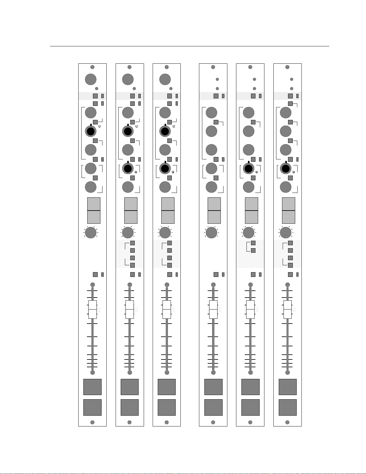
Input Module Faceplates (dwg)....................................................... 1-3
Mono mic/line input ........................................................................ 1-4
Stereo line input............................................................................... 1-4
Group and Output Module Faceplates (dwg) .................................. 1-5
Group modules ................................................................................ 1-6
Stereo Master Output module.......................................................... 1-4
Control room module ...................................................................... 1-4
Monitor Module Faceplates (dwg) .................................................. 1-7
Accessory Module Faceplates (dwg)............................................... 1-8
Studio module.................................................................................. 1-9
Stereo line selector module ............................................................. 1-9
Tape remote module ........................................................................ 1-9
Superphone module ......................................................................... 1-9
Intercom module............................................................................ 1-10
SP-44 (48) System Signal Flow Diagram ..................................... 1-11
SP-42 System Signal Flow Diagram ............................................. 1-12
Performance Specifications ........................................................... 1-13
SP–40 SERIES DESCRIPTION
The Wheatstone SP-40 console series is a dual purpose design intended for
applications where the console will be used for both production work and on-
air applications. As such, its module layout has characteristics similar to both
traditional on-air boards and production models. Generally speaking, the
lower half of a typical input module emulates on-air control layout, while the
upper half contains equalization and send controls. This hybrid architecture
allows both production and on-air personnel to easily learn and operate all
models of the series.
There are three models: the SP-42 (intended for 2-track use), the SP-44 (4-
track) and the SP-48 (8-track). All models are similar in layout, but differ
primarily in the number of outputs available. The standard model is the SP-44.
SP-44 Four-track Production Console
This console comes equipped with four subgroups, two stereo outputs
(Program and Audition), one mono sum output (Program L+R), one mix-
minus output, three auxiliary sends and cue. Intended to interface with a four-
track tape recorder (the subgroup outputs feed the recorder; multitrack playback
is normally through the subgroups' tape inputs), the console may be ordered
with 16 or 24 input channels. The mainframe includes VU meters for the
subgroups, Program (left & right), Audition (left & right), and Mono (Program
L+R). Group VUs can also meter the three sends and mix-minus, via front
panel switching on the subgroup modules. A control room monitor module is
standard equipment. The mainframe has room for five accessory modules
(three on the right and two on the left).