Wheatstone LXE 5 User manual

LXE
600 Industrial Drive, New Bern, North Carolina, USA 28562
Digital Control Surface
Quick Start Guide
WheatNetIP LXE Surface Setup GUI 1.6.3 and higher

Quick Start - page 1
LXE / Feb 2018
QUICK START GUIDE
Installation and Configuration
Introduction
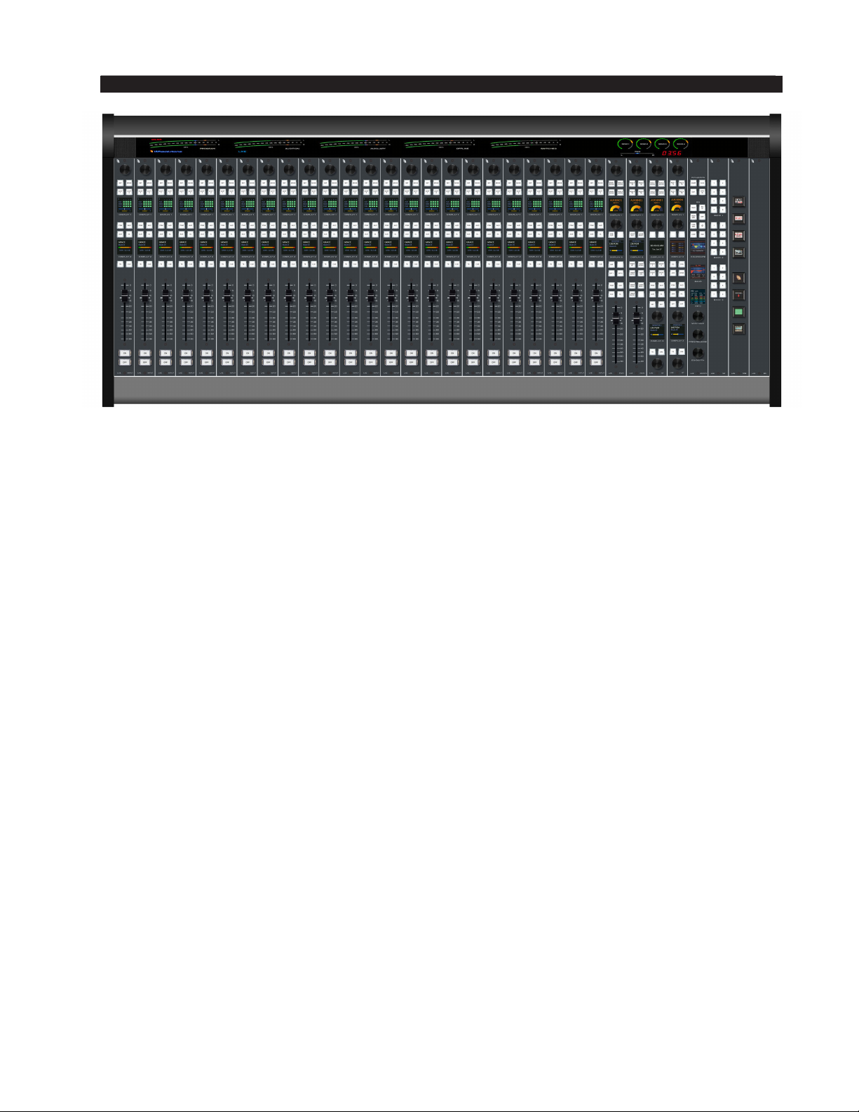
Wheatstone’s new LXE console brings control surface conguration to a new level.
Going far beyond the usual “any source to any fader” network concept, the LXE is a fully
exible control interface, where every switch, fader, and rotary control is programmable to
perform any available function. This means console architecture is completely customizable
to client requirements, and limitations to functionality are no longer a factor. Physically
compact, the LXE is available in several different form factors including countertop,
countertop sunken, and split frames (split sections are not conned to one room, they can
actually be in different studios).
LXE Surface Setup GUI allows every switch on the surface to be programmed for
function, mode, and even color (switches are RGB led illuminated). In fact, built-in
software allows every button to be scriptable, letting you create powerful macros for as
many controls as you want. Multiple full color OLED displays on each panel keep pace
with ongoing operations, and event recall allows painless one touch console reconguration
at the press of a button. With its inherent control exibility and ability to access thousands
of signals (sources and destinations are limited only by the size of the network) the LXE
takes facility work ows and audio control to a new level.
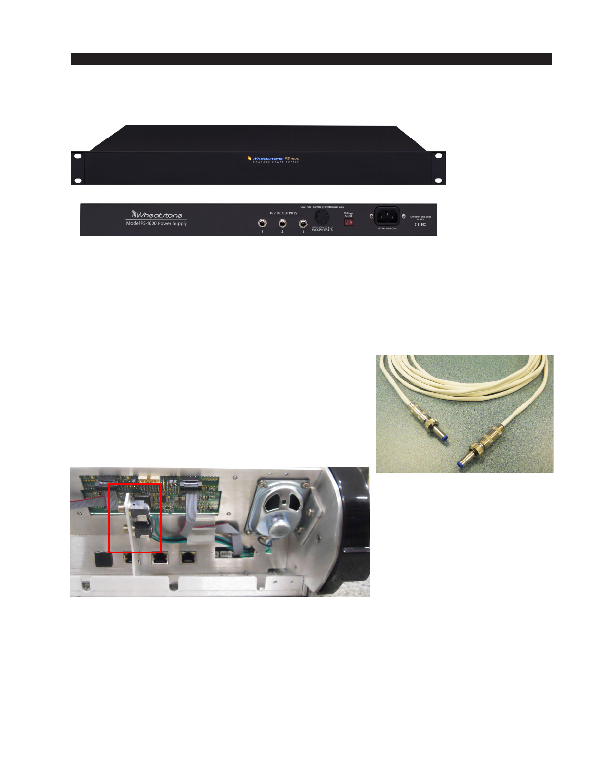
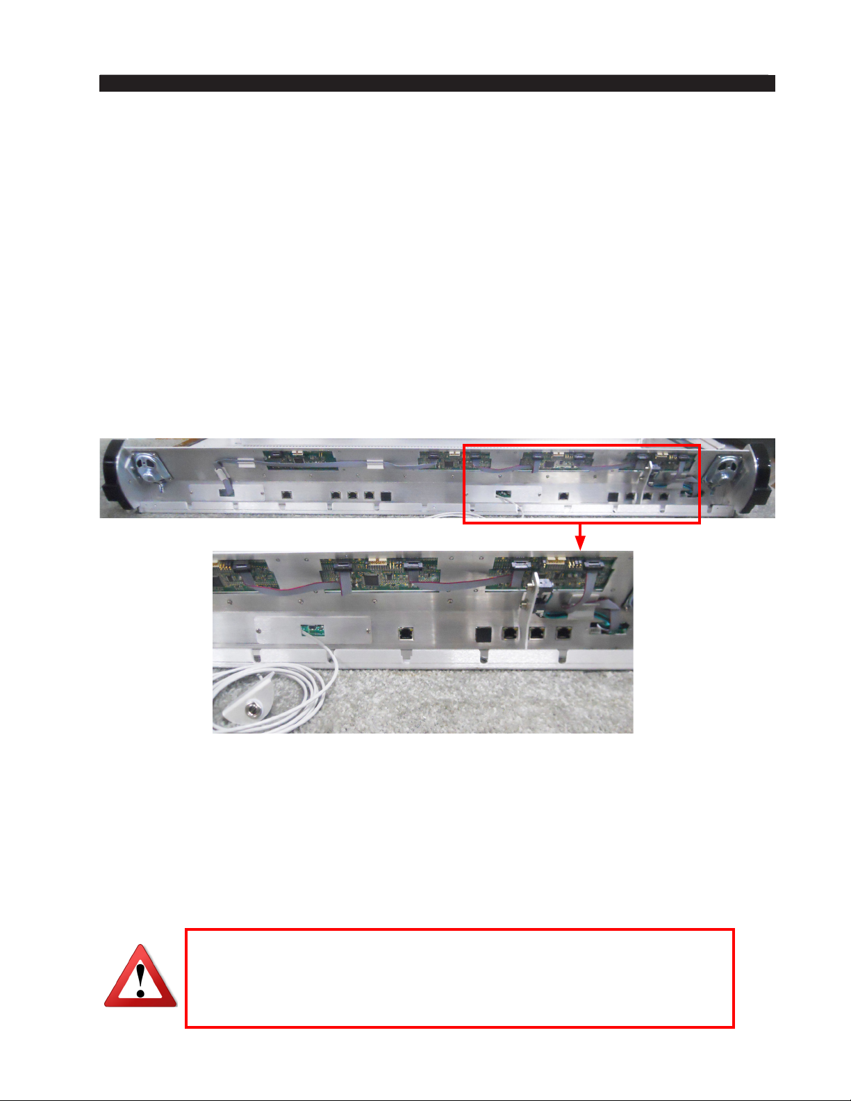
The LXE can have up to 32 physical motorized faders, with full DSP processing
available on all 32 channels. Surface(s) interface seamlessly into the WheatNet-IP Intelligent
Network, and utilize BLADE-3s for audio, control and associated logic data owing on
single CAT6 interconnecting cables. The system can ingest and convert virtually all audio
formats: analog, microphone, AES/EBU, SPDIF, AoIP, MADI, SDI and even AES67.
Loudness metering, phase control, and full EQ/Dynamics are included.
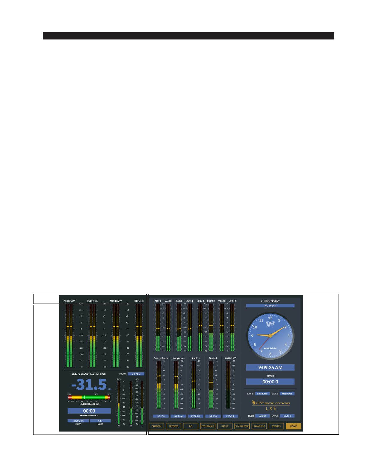
LXE’s new GUI has pre-built screens for everything you normally use – metering,
clocks, timers, dynamics, EQ, assigns, and more. All are touch-screen accessible with
gestures you’re used to using on your smart devices. And, the GUI is just as customizable
as the LXE surface. Using our ScreenBuilder-LXE software, you simply drag and drop
objects and dene their functions via a simple wizard interface. You can store multiple
custom screens, if you like, to go with your custom LXE setups.

Quick Start - page 2
LXE / Feb 2018
QUICK START GUIDE
Control Surface Placement
The LXE modular control surface is designed for countertop mounting or drop-in
installation in counter top.
Although the rubber feet on the bottom keep the surface from being easily moved when
simply placed on the counter, pre-drilled holes have been provided so that screws may be
used to mount the surface securely to the countertop. Locate the LXE on the counter, and
remove the screws (two per module) that hold the second and next to the last modules
in place (for the 33/37/45-positions frame remove also module in the middle). Carefully
remove these modules from the frame. Attach the mainframe to the counter top, using the
holes provided in the bottom of the chassis and screws appropriate to the counter material,
and reinstall the removed modules.

Quick Start - page 3
LXE / Feb 2018
QUICK START GUIDE
Countertop Frames
4-5/16"
4-27/32"
21-17/32"
18-7/32"
1-19/32"
2-1/8"
7-13/16" - 5-POS. FRAME
19 -7/8" - 13-POS. FRAME
25-29/32"- 17-POS. FRAME
31-15/16" - 21-POS. FRAME
13 - 27/32" - 9-POS. FRAME
37- 31/32" - 25-POS. FRAME
44"- 29 - POS. FRAME (shown on drawing)
50-1/16" - 33-POS. FRAME
56 -1/16"- 37-POS. FRAME
68-1/8"- 45-POS. FRAME
9-13/16" - 5-POS. FRAME
21-7/8" - 13-POS. FRAME
27-29/32" - 17-POS. FRAME
33-15/16" - 21-POS. FRAME
15-27/32" - 9-POS. FRAME
39-31/32" - 25-POS. FRAME
46"- 29-POS. FRAME
21-17/ 32"
4 HOLES D=3/16"
USE #8 SCREWS TO ATTACH TO COUNTER
6 HOLES D= 3/16"
USE #8 SCREWS TO ATTACH TO COUNTER
3-3/8" 3-3/8"
3-3/8" 3-3/8"
52-1/16"- 33-POS. FRAME
58-1/16" - 37-POS. FRAME
70-1/8" - 45-POS. FRAME
22-21/ 32" - 33-POS. FRAME
25-21/32" - 37-POS. FRAME
31-11/16" - 45-POS. FRAME
22-21/ 32" - 33-POS. FRAME
25-21/32" - 37-POS. FRAME
31-11/16" - 45-POS. FRAME
LXE 33(shown on drawing)/37/45-POS. FRAME
12"
4-3 / 8"
12"
4-3 / 8"
LXE 5/9/13/17/21/25/29(shown on drawing)-POS. FRAME
3-1/16" - 5-POS. FRAME
15-1/8" - 13-POS. FRAME
21-5/32" - 17-POS. FRAME
27-3/16" - 21-POS. FRAME
9-3/32" - 9-POS. FRAME
33-7/32" - 25-POS. FRAME
CUTOUT DIMENSIONS
5-POS. FRAME - 8 -1/16" x 18-1/2"
9-POS. FRAME - 14-3 /32" x 18-1/2"
13-POS. FRAME - 20 -1/8" x 18-1/2"
17-POS. FRAME - 26-1/4" x 18 -1/2"
21-POS. FRAME - 32-3/16" x 18-1/2"
25-POS. FRAME - 38-7/32" x 18-1/2"
29-POS. FRAME - 44 -1/4" x 18-1/2"
33-POS. FRAME - 50- 3/8" x 18 -1/2"
37-POS. FRAME - 56 - 5/16" x 18-1/2"
45-POS. FRAME - 68 - 3/8" x 18 -1/2"
21-17/ 32"
39-1/4" - 29-POS. FRAME

Quick Start - page 4
LXE / Feb 2018
QUICK START GUIDE
Wedges Frames
4 HOLES D= 3/16"
USE #8 SCREWS TO ATTACH TO COUNTER
20-3 /8" 12"
4-3/ 8"
6 HOLES D= 3/16"
USE #8 SCREWS TO ATTACH TO COUNTER
20-3 /8" 12"
4-3/ 8"
3-3/8" 3-3/8"
52-1/16"- 33-POS. FRAME
58-1/16" - 37-POS. FRAME
70-1/8" - 45-POS. FRAME
22-21/ 32" - 33-POS. FRAME
25-21/ 32" - 37-POS. FRAME
31-11/16" - 45-POS. FRAME
22-21/ 32" - 33-POS. FRAME
25-21/ 32" - 37-POS. FRAME
31-11/16" - 45-POS. FRAME
LXE 33(shown on drawing)/ 37/45-POS. FRAME
LXE 5/ 9/13/17/21/25/29(shown on drawing)-POS. FRAME
7-13/ 16" - 5-POS. FRAME
19 -7/8" - 13-POS. FRAME
25 -2 9/ 32"- 17-POS. FRAME
31-15/ 16" - 21-POS. FRAME
13 -2 7/32" - 9-POS. FRAME
37-3 1/32" -25-POS. FRAME
44"- 29- POS. FRAME (shown on drawing)
50-1/16" - 33-POS. FRAME
56 -1/16" -37-POS. FRAME
68-1/8"- 45-POS. FRAME
CUTOUT DIMENSIONS
5-POS. FRAME - 8- 1/16" x 18 -1/2"
9-POS. FRAME - 14-3/ 32" x 18-1/2"
13-POS. FRAME - 20- 1/ 8" x 18 -1/2"
17-POS. FRAME - 26-1/ 4" x 18-1/2"
21-POS. FRAME - 32- 3/ 16" x 18-1/2"
25-POS. FRAME - 38-7/32" x 18 -1/2"
29-POS. FRAME - 44- 1/4" x 18 -1/2"
33-POS. FRAME - 50- 3/ 8" x 18-1/2"
37-POS. FRAME - 56- 5/16" x 18- 1/2"
45-POS. FRAME - 68- 3/8" x 18-1/2"
9-13/16" - 5-POS. FRAME
21-7/8" - 13- POS. FRAME
27-29/ 32" - 17-POS. FRAME
33-15/ 16" - 21-POS. FRAME
15-27/32" - 9- POS. FRAME
39-31/ 32" - 25-POS. FRAME
46"
- 29- POS. FRAME
3-3/8" 3-3/8"
3-1/16" - 5- POS. FRAME
15-1/8" - 13-POS. FRAME
21-5/32" - 17-POS. FRAME
27-3/16" - 21-POS. FRAME
9- 3/32" - 9- POS. FRAME
33-7/32" - 25-POS. FRAME
39-1/4" - 29- POS. FRAME
1-19/32"
18-7/32"
2-7/8"
2-11/32"
2-7/8"

Quick Start - page 5
LXE / Feb 2018
QUICK START GUIDE
Power Supply
Front view of the PS-1600
rackmount power supply
Rear view of the PS-1600
rackmount power supply
If failsafe redundant sup-
plies have been ordered,
you will be installing two
PS-1600 units.
In case of redundancy use two PS-1600 units. If you are using one supply, connect
it to one of the control surface connectors (it doesn’t matter which one). If you are
using the failsafe option (two PS-1600 supplies), connect one end of a power supply
cable to either control surface power connector and connect the other end of the cable
to one of the two power supply units. Then use the other cable to connect the second
power supply to the remaining control surface power supply connector.
The LXE control surface is powered by a Wheatstone Model PS-1600
rackmount power supply. This unit occupies a single 19” wide rack space.
Convection cooled, it requires ample ventilation space above and below it.
Note the power supply (supplies) should be mounted in an equipment
rack within fteen feet of the control surface (but no closer than 3 feet).
Avoid locating any high gain equipment too near the rackmount supplies,
to avoid magnetic interference into that equipment.
Once the supply is rackmounted, it should be connected
to the control surface using the factory supplied DC power
cable.
Unscrew the LXE’s rear panel to access its power
connectors that mounted on the bracket on the right side
of the chassis. The cable has two DC plugs on it.

Quick Start - page 6
LXE / Feb 2018
QUICK START GUIDE
Note each power supply is tted with a 3-wire grounded AC cord
that should be plugged into a “clean” AC power source, that is, an AC
source that feeds only the control room audio gear. This source should
be a separate feed from those powering lighting, air-conditioning, or any
other non-audio machinery. The third pin ground wire of the AC source
should be tied to the central system ground point.
The power feed recom-
mended in the text is often
installed and referred to in
studios as an “isolated AC
ground” outlet. It is usually
orange in color.
Wiring to and from the LXE control surface is made via connectors mounted on the
rear of the control surface.
Unscrew the rear panel to make power supply, headphone connections.
Headphone connection is made via factory supplied cable with a TRS headphone jack
connected to a bracket that can be mounted to the counter for your convenience, and a
3-pin JST plug that plugs into the Panel Host board (PH12-LXE/PH8-LXE/PH4-LXE).
There are several RJ-45 connectors on the rear of the LXE control surface. This number
will vary depending on the size of the surface. Chose only one of the open connectors for
the connection to a standard Ethernet network switch via a straight (pin to pin) CAT6 cable.
Failsafe Dual Redundant Supply
Wheatstone failsafe power supply systems use two PS-1600 power supplies for each
piece of powered equipment. Though either is capable of running a full load on its own,
in failsafe operation both units run in tandem: if one fails, the other takes over, assuring
uninterrupted operation.
In order for failsafe systems to perform as designed, always have BOTH rackmount
supplies powered up and connected to their associated equipment.
Connections
Warning!
If you connect more than one of the available Ethernet ports to your
network switch, you will cause a spanning tree loop in the switch and
the switch will disable the extra ports to which you have connected to.

Quick Start - page 7
LXE / Feb 2018
QUICK START GUIDE
Energizing
Assuming the LXE control surface mainframe is properly placed and it’s PS-1600 power
supply (or supplies) are correctly rack mounted and connected to the control surface, you
may now energize the rack mount power supply by plugging it into the AC mains.
Note: To de-energize the control surface, unplug the rack mount power supply’s AC
cord from the AC mains. Never de-energize the control surface by disconnecting the cable
that connects the control surface and power supply together.
Surface Scanning
At power-up the LXE performs a scan to identify the module positions in the control
surface. If you rearrange the module layout you must restart the control surface.
Getting Started
The LXE control surface comes with an Embedded Graphical User Interface (GUI)
program, intended to be straightforward in use, with controlling and displaying graphics,
production tools, and set up screens. The LXE HDMI monitor is divided into several
sections. The upper left is the METERING PANE for the main program buses. The lower
left side is used to display the Loudness or Phase metering. The middle metering section
displays metering for the Aux Send Busses and Mix-Minus Send Busses. This middle
metering section is congurable to allow for maximum exibility. On the right side of
the screen there are analog and digital clocks, timers, and event information. All controls
of the GUI’s main screen are in xed positions, except that the FUNCTION PANE area
contents change according to selected function.
Connect the user-supplied HDMI touch monitor or other display to the HDMI connector
on the Mix Engine’s rear panel, power up the surface and the Mix Engine BLADE and
the GUI will appear.
SOURCE
METERING PANE
FUNCTION
FUNCTIONS PANE
BUTTONS

Quick Start - page 8
LXE / Feb 2018
QUICK START GUIDE
Button Navigation
The LXE GUI features a “button” navigation architecture to easily access features with
a minimum number of clicks. This section introduces you to the buttons; detailed function
information is included in the module sections.
The Function buttons are located across the bottom of the function display area. You
may access any desired screen by simply clicking or touching the appropriate buttons
Home Button – Displays Timer, Clock, Current Event, Switched Meter, Metering of
Program, Auxiliary, and Mix-Minus busses, External Source for monitors, and User and
Layer information.
Events Button – The LXE can store a “snapshot” of the entire control surface in a le
called an EVENT. The Event Pane is divided into two sections. The Event Recall section
lets you recall previously saved Events. The Event Editor is a manager for creating,
editing, and deleting Events. Optional permissions let you limit access to Event Recall
and Event Editor functions.
Aux/MixMinus Button – Displays controls for the four Aux Master outputs and the
Mix‑Minus Outputs.
X/Y Router Button – Opens up the XY router screen.
Input Button – Displays interactive Source, Mode, Phase, Pan, and Aux Send settings
for the selected channel. Note you must press an Input fader’s SET button to show the
settings for that channel, or click on a CHANNEL SELECT button in the upper left side
of the Input screen on the HDMI display to access any fader.
Dynamics Button – Here you can set the available dynamic settings for the selected
channel. Expansion and Compression settings are set based on the Input fader’s SET
button or click on a CHANNEL SELECT button in the upper left side of the Dynamic
screen.
EQ Button – Here you can set the available EQ settings for the selected channel. EQ In,
High and Low Pass Filters, Lo and High Shelf settings are set based on the Input fader’s
SET button or click on a CHANNEL SELECT button in the upper left side of the EQ
screen.
Presets Button – Here you can assign dynamics, EQ, Stereo Mode, Pan position or Aux
Send or any combination to an input fader, or all input faders as desired in a recallable
preset for any single or all faders on the LXE surface.
Custom Button – Here you can launch custom built screens based on our popular Screen
Builder Product.

Quick Start - page 9
LXE / Feb 2018
QUICK START GUIDE
Users
When the surface boots, it enters user prole that was last accessed. Look in the lower
right of the screen, under the Wheatstone LXE logo to see the current user prole. From
the Factory the user Default will be loaded.
Pressing or clicking on the Current User will open a list of users dened in the LXE
Surface Setup GUI. From the Factory, only one user exists called “Default.” The Default
user will have full access and control over all surface functions.
Once a given user prole is selected, that setting will persist through a power cycle
or surface reset.
More detail on user proles can be found in the LXE Surface GUI Setup.
Network Settings
When your surface is connected to the WheatNet‑IP network for the rst time it will
need to be congured to connect with a mix engine.
The Surface Host (Linux host inside the Mix Engine) requires a network connection
as well as the LXE surface. The LXE surface will use Link-Local addresses to commu-
nicate internally and to its associated host, therefore no IP conguration is required for
the LXE Surface.
The LXE surface Host will come congured with a default IP address of 192.168.87.90.
To changethe IP address to something other than factory default, from the Hardware menu
of the LXE setup GUI you will need to select Setup Host. Select the surface you wish to
change from the list and modify the properties of the surface. From here you can set the
Name, Locations, and Network settings. Pressing enter in each eld applies the settings.
Reboot the surface once your changes have been applied. You can conrm the change
by using the locator function in Navigator or the LXE setup GUI. You may also press
“<ctrl> I” on the Surface host keyboard (if connected) to launch the Info screen. If using
a touch screen/mouse this information is displayed by clicking theWheatstone LXE logo
in the lower right of the surface GUI.
Surface Software Version
In the event that you need to consult the factory about the LXE control surface, you
may need to have the surface software version number available. Press “<ctrl> I” on the
keyboard or by clicking the Wheatstone LXE logo in the lower right of the surface GUI
to display the current running version of software.

Quick Start - page 10
LXE / Feb 2018
QUICK START GUIDE
LXE Modules

Quick Start - page 11
LXE / Feb 2018
QUICK START GUIDE
By now you have read that the LXE is fully customizable. Each encoder, button, and
screen can be programmed to any desired function. This is great news, as your mixing
surface will not have the limiting factors as in the past. With this said, we should point
out that when we build your LXE at the factory, it will be “pre programmed” with the
most basic functions so that you don’t have to spend hours learning the custom parts to
just get the surface up and running. In the Sections below we will cover the new features
added to each module and note how each button and switch and OLED screen should
function using a “factory” image or setup. Most but not all functions will be similar to
our legacy surfaces.

Quick Start - page 12
LXE / Feb 2018
QUICK START GUIDE
Input Module
The LXE features a new design for input modules. The new design incor-
porates a rotary encoder on each input panel, 2 full color OLED displays to
give operators quick at a-glance information about Program, Aux and Mix
Minus assignments, Stereo Position, Source Selection, cue status and more. All
encoders, displays, and buttons have been programmed with factory congu-
ration unless otherwise specied. If a custom conguration is needed, each is
custom denable using the LXE Surface Setup GUI. Please refer to the LXE
Surface Setup GUI part of the manual for more details on customizing input
module displays, buttons and rotary encoders.
Below we will describe the factory dened functions, giving a quick overview
of what each control does, and how it is used. For more information on these
features and other customizable function please refer to the surface user manual.
Rotary Encoder
Each input fader has an Encoder at the top that has been factory congured
to be a X Controller. Rotating the encoder allows you to look through the list
of available sources. Press the encoder to TAKE the selected source. Taking
the source changes the text color from red to white indicating that source has
now been assigned to the input fader.
Depending on how the LXE is congured, you may be able to select any
source in the system or you may have a subset of sources for one or more of
the inputs. This is based on the Visibility settings in the LXE Surface Setup
GUI, under the User Options Visibilities tab.
SET Button
The SET button is located at the top of the module under the new rotary
encoder. Pressing the SET button switches the LXE surface GUI screen to the
INPUT screen for this fader, where you can change the programmed source,
select the fader mode, adjust panning, and set up Aux Sends, Mix Minus.
Once lit, the SET button stays lit until you light SET on a different fader,
or deselect the fader.
Input Screen
When you press an Input fader’s SET button the LXE Surface GUI display
switches to the Input screen for that channel. You can click on various buttons
to congure the channel for your application.

Quick Start - page 13
LXE / Feb 2018
QUICK START GUIDE
A typical Input Source screen is shown below followed by descriptions for each of
the functions.
Channel Select
The input fader number for which the set button is pressed is displayed here. You may
also navigate to other input fader by clicking on the grey CHANNEL SELECT button.
Select the desired fader number and the screen will update with the new information.

Quick Start - page 14
LXE / Feb 2018
QUICK START GUIDE
Source Window
The source box on the input screen shows you the current source assigned to that
fader. Clicking in the SOURCE eld on the LXE Surface GUI screen opens the INPUT
SOURCE SELECTOR window. Select the LOCATION on the left, which will display the
list of sources on the right. The LOCATION information comes from the Location eld
in your Wheatnet‑IP BLADE System labels location eld.
Highlight a location, then a source, then press TAKE to apply the source to the Fader
Input.
You may use the Visibility feature in the LXE Surface Setup GUI, to limit the signal list
the user “sees” when selecting sources. This feature is especially useful in large systems
with many sources. This is described in the LXE Surface Setup GUI section.
Mode Button
Each Input Module has a MODE Button. Use this button to quickly change the input
fader mode from STEREO, MONO, LEFT ONLY, RIGHT ONLY or SURROUND without
the need to put the module into SET MODE.
Mode Controls and Indicators
There are four available input fader modes: Stereo, Mono, Left only, and Right only.
You can choose the desired mode by pressing MODE Button on the LXE Input module.
The channel’s MODE indicators in the OLED DISPLAY 1 (by default) will change to
reect the new mode.
To choose the desired mode using the LXE Surface GUI screen click on the desired
mode, and the channel’s MODE indicators on the OLED DISPLAY 1 will change to reect
the new mode.
STEREO – Selects stereo mode; Left in feeds fader L, right in feeds fader R. If a mono
source is selected, it will feed both L and R.

Quick Start - page 15
LXE / Feb 2018
QUICK START GUIDE
MONO – Selects mono mode. If a stereo source is selected it is summed to mono and
reduced by 6dB.
LEFT (left only) – Passes only the left channel of a stereo source to both L and R.
RIGHT (right only) – Passes only the right channel of a stereo source to both L and R.
Pan
L/R - Slider moves the signal left to right.
Phase
A pair of buttons, one for left and one for right, located on the LXE Surface GUI
“INPUT” screen, are provided to allow for the reversal of absolute phase of the source
signal input.
Soft Buttons
Each fader strip has been factory congured with two programmable (SOFT) buttons.
These buttons are programmed in the new LXE Surface Setup GUI application. See the
LXE Surface Setup GUI part of the manual for more information on programming these
or any other buttons.
Assign Switches
Program assign switches place the selected source signal to any combination of the
surface’s four stereo outputs – PGM (program), AUD (audition), AUX (auxiliary), and
OL (off line). The button will be lit when the source is assigned to its respective bus. To
remove a source from the bus, press the button again; the light will go off to indicate that
the source is no longer assigned to that bus.
The OL Bus
The OL bus has a special function in relation to a channel’s Bus Minus output. Each
signal that can be assigned to a channel will specify which bus (PGM, AUD, AUX, or OL)
provides the base Bus Minus mix (that is, which bus the Bus Minus output is a mix-minus
of) when that channel is on. When the channel is off, however, the base Bus Minus mix
may be the same as when the channel is on, or may be congured to utilize the OL bus
instead. This allows the Bus Minus output to have different content when the channel is
off than it does when the channel is on.
Both the base Bus Minus mix and the use of the OL bus as base when the channel
is off are congured in the VDip settings. VDip settings are located in the LXE Surface
Setup GUI under the USER Options Tab.
MXM Assign Indicators
Each channel can be assigned to any combination of the four MIX-MINUS busses.
The MXM ASSIGN 1‑4 in OLED DISPLAY 1 gives the operator a quick indication of
what mix-minus busses the source is assigned to.
Channels are assigned to these MXMs in the following manner: press the SET button
on the input fader section and then press the desired MXM ASSIGN button, located on
the Headphone module or Input Screen on the LXE Surface GUI.
Note that you are normally assigning the channel, and not the source, to the MXM bus.

Quick Start - page 16
LXE / Feb 2018
QUICK START GUIDE
OLED Displays
The LXE Surface features two color OLED Displays. As with everything on the
LXE, these displays can be customized as to what they will display to the user. From
the Factory these will display the following:
OLED DISPLAY 1
Input Assignments: Fader number, AUX, MXM, and PGM assigns,
Signal MODE (i.e. STEREO) and panned position if used.
OLED DISPLAY 2
Input Source Meter
Shows Selected Source Name, Input Gain Value, and EQ or DYN,
Cue applied to the fader.
TB Button
The TB Switch routes the TB audio, typically the operator’s microphone, to the BUS
MINUS output for that channel, allowing the operator to talkback to the talent hearing
that BUS MINUS signal.
CUE Button
The CUE switch assigns the selected source to the CUE bus, letting the control
surface operator monitor the channel’s pre-fader signal.
Bus-Minus / Direct Outputs
Each fader has a dedicated Bus-Minus output that includes all active faders on its
selected source bus, except for itself. These auto generated mix-minus signals may be
routed to feed telephone hybrids, remote operator feeds, or other devices as required.
Bus-Minus mix outputs for each surface fader appear as Sources in the Surface signal
area of Navigator. A typical Bus-Minus output signal name is LXEBM01 but the exact
name depends on the fader and surface ID number.
Any of the four output busses, four Aux busses, or four Mix Minus busses may be
selected in the User options VDip settings (see the LXE Surface Setup GUI to assign
VDips) as the source bus.
Another selection that can be made in VDip is to repurpose the fader’s Bus Minus
output as a Direct Output. This option might be used if multitrack recording is needed.
Fader
Channel output level is set by a 100mm, professional, conductive plastic linear fader.
If the signal feeding the busses goes into clipping briey the OVERLOAD light will
ash briey. If the signal is continually clipping the OVERLOAD will ash steadily.
Clipping can be stopped by moving the fader down, or reducing the signal level in some
other fashion.

Quick Start - page 17
LXE / Feb 2018
QUICK START GUIDE
Channel ON Button
The channel ON switch turns the channel signal ON and res any channel ON (START)
logic mapped to the fader’s source signal. By default the Machine Start LIO function is
disabled. In order to send the Machine Start LIO to a remote device this must be enabled
in the LXE Surface Setup GUI. The switch LED lights to indicate the channel is ON
and the ON‑AIR LED will light on the meterbridge if congured in the Surface VDips.
Channel OFF Button
The channel OFF switch turns the channel signal OFF and res any channel OFF
(STOP) logic mapped to the fader’s source signal. By default the Machine Stop LIO
function is disabled. In order to send the Machine Stop LIO to a remote device this
must be enabled in the LXE Surface Setup GUI. The switch LED lights to indicate the
channel is OFF.

Quick Start - page 18
LXE / Feb 2018
QUICK START GUIDE
Output Section
Each LXE control surface has two Monitor
modules, and one Studio module. There are
two Studio module types, either can control
any of the Monitor feeds. Additional Monitor
and Studio Modules can be added if needed.
As we discussed in the Input section, the
LXE surface is fully customizable down to
each button/switch, OLED Screen and Rotary
Encoder. The descriptions provided here are
what the LXE Surface will have programmed
from a factory default perspective.
Although they are individual modules,
they are designed to function as a group.
For example, one of the four AUX Send1 ‑
AUX Send 4 Level controls is located on the
top of each module. In this guide we will
describe the controls and functions of these
modules as a group starting from the top of
the modules and going down.
Rotary Encoder
This encoder is programmed from the
factory to be the Master level control for the
AUX Bus.
AUX Busses
The control surface has fourAUX busses,
which can be used to create record feeds, extra
mix-minus busses, etc. The Aux Send 1- 4
Assign buttons are just below the Encoder
on the Studio module. Input to an Aux Send
control can also be accessed using the Aux
assignment section of the main Input screen of
the LXE Surface GUI. Each AUX BUS feed
has Mode, Pre‑fader and Pre‑On switches,
and On/Off controls. A virtual AUX BUS
knob indicates relative level. Use the physical
Aux SEND knobs on the top of modules or
the mouse on the screen to adjust levels. All
adjustments can be saved to a Channel, a
Source, an Event, or a Preset.

Quick Start - page 19
LXE / Feb 2018
QUICK START GUIDE
TheAux SEND LED indicators are displayed on the meterbridge,
and additionally in OLED DISPLAY 1.
Pressing the AUX/MXM button in the LXE Surface GUI switches the screen to the
AUX and MIX MINUS MASTERS screen with four AUX MASTERS level controls
and ON buttons.
AUX Talkback
If your LXE surface is equipped with a second Studio Module, interrupt an Aux
bus signal with the surface’s predened TB signal by pressing the AUX 1‑ 4 TB switch
located on Studio module below the Encoder. This allows the control surface operator
to communicate with the Talent or location receiving that Aux send.
Note that the talkback source, typically a host mic, must rst be cross‑connected to
the surface’s TB input using either Navigator software or the LXE’s X/Y Router button.
The TB signal may be any source signal in the router including MXM or Aux busses.
The LXE’s TB input signal is a factory dened surface Destination signal with the name
LXETkBk.
MXM ASSIGN Buttons
These physical buttons are used to route input fader strips to MIX MINUS busses.
Press the SET button on any channel. If that channel is assigned to feed an MXM bus,
the corresponding MXM ASSIGN switch and OLED indicator on the fader strip will be
lit. Pressing an MXM ASSIGN switch will toggle that channel’s signal into or out of the
corresponding MXM bus. The Mix-Minus 1- 4 Assign buttons are just below the Level
control on the rst Monitor module.
MXM Master Controls
Click the Aux/MixMinus Button on the LXE Surface GUI screen to bring up the
MIX MINUS MASTERS controls. Each MXM Master has a PRE‑FADER and PRE‑ON
switch as well as a virtual Level control.
PRE‑FADER – Normally any signal feeding a Mix Minus does so with a post‑fader
signal. Selecting the PRE FADER button for a given Mix‑Minus bus globally congures
the MXM bus to tap off the input strip audio before the fader.
PRE‑ON – Normally any signal feeding a mix‑minus does so with a post‑ON switch
signal. Selecting the PRE‑ON button for a given Mix‑Minus bus globally congures the
MXM bus to tap off the input strip audio before the channel ON switch.
Note: Mix Minus Invert and Follow Source functions have moved exclusively to the
LXE Surface Setup GUI. See the LXE Surface Setup GUI part of the manual for more
details.
This manual suits for next models
9
Table of contents
Other Wheatstone Music Mixer manuals