Page 2
Adjust RADIO or PA
volume, using a flat
blade screwdriver.
PA
VOL.
RADIO
VOL.
Feature Summary:
Congratulations on selecting the 295SDA2
Dual Siren Control Center. This unit offers a
unique collection of features designed to
allow the user to customize the operation to
suit their individual needs. Features include:
Siren:
•Two independent siren amplifiers that can
drive one 100 watt siren speaker each.
• Non-destructive short circuit protection.
• Under/over voltage protection.
• Title 13 compliant tone set up.
• 20 programmable tones.
• Any combination of 2 tones can be
programmed to any siren tone switch.
• Horn-ring transfer relay built in.
• Siren “in use” icon driver output.
• Siren disable (Park kill) control input.
• Includes Radio Repeat and PA.
Lighting control:
•7 Programmable lighting control Switches.
• Three 20 Amp relay controlled outputs with
built in fuses.
• Eight 10 Amp relay controlled outputs with
built in fuses (two of them include a choice of
independent inputs or the standard power bus
switching).
• Two wire TrafficAdvisor™ control.
• Programming can not be activated by a user
in the cab.
• All lighting switches can be programmed to
activate any combination of relay outputs.
• All lighting switches can be programmed to
activate or deactivate switches SW5 - SW8.
• Lighting switches can be programmed to be
activated as either a push-on / push-off,
momentary, flashing, timed output TA control
or Alley (ALY) control.
• All lighting switches can be programmed to
activate the siren into HF mode.
• Copy one units configuration to another unit,
“CLONING”.
• Reset to factory default settings.
• Change the “Shutdown Delay” time.
• Program the backlight intensity of the control
head.
Installation:
Caution: Mounting will require drilling. It is absolutely necessary to
make sure that no other vehicle components could be damaged in
the process. Check both sides of the mounting surface before
starting. If damage is likely, select a different mounting location.
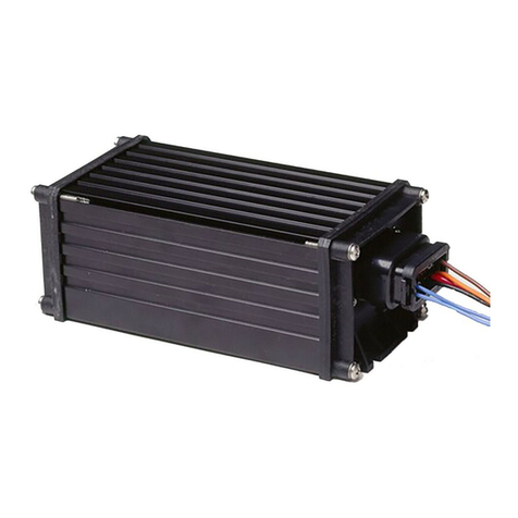
295SDA2 Module:
1. Find a mounting location. A dry,
cool compartment is a good
choice.
2. Position the unit on the
proposed mounting location.
Using an awl or similar tool,
scribe the mounting surface
where the mounting holes are
to be drilled. Make sure that
this mounting area allows
sufficient ventilation for the unit.
3. Remove the unit and using a drill bit sized for a #10
sheet metal screw, drill a hole in each of the areas scribed in step 2.
4. Return the unit to its mounting location and using #10 x 3/4” sheet
metal screws (provided), secure the unit onto its mounting surface.
Be sure to install a #10 internal tooth lock washer (included) onto
each mounting screw before mounting the unit. IMPORTANT: The
module must be mounted on, or grounded to the vehicle chassis.
Hand-held Controller/Microphone
The system is controlled using a hand-held controller with a microphone
(with Push-To-Talk key) and 12 illuminated push-buttons.
IMPORTANT: Do not remove the protective plastic from the control
head until the installation is complete!
The mounting bracket for the controller should be located within a
comfortable reaching distance from the operator.
Do not install this product or route any wires in the air bag
deployment zone of your vehicle. Equipment mounted or located in
air bag deployment zones will damage or reduce the effectiveness of
the air bag, or become a projectile that could cause serious personal
injury or death. Refer to your vehicle owner’s manual to learn the air
bag deployment zones for the vehicle. The User/Installer assumes
full responsibility to determine proper mounting location, based on
providing ultimate safety to all passengers inside the vehicle.
SL1 SL2
H/F MAN A/H
SIR
SW6
RAD
SW7
SW5
SW8
SL3
Button
Decal
Plate
NOTE: The controller is shipped
without any button decals installed.
Do not place button decals directly
onto the buttons. Install a plate onto
each button first and then adhere the
desired button decal onto that plate.
Wiring:
WARNING: All customer supplied wires that connect to the positive
terminal of the battery must be sized to supply at least 125% of the
maximum operating current and FUSED at the battery to carry that
load. DO NOT USE CIRCUIT BREAKERS WITH THIS PRODUCT!
Siren Input (J7) - RED: Power - BLACK: Ground
1. Splice the 2 RED (Power) wires together, then extend this single
RED wire toward the vehicle battery. Splice the 2 BLACK (Ground)
wires together and extend this single BLACK wire toward the vehicle
battery. To pass the RED and BLACK wires through, you may have to
drill a hole in the firewall. Insert a grommet to protect the wires.
2. Route the RED and BLACK wires along the factory harness towards
the battery and install a fuse block (user supplied) on the end of the
RED wire. Remove fuse from fuse block before connecting any
wires to battery.
3. Connect fuse block wire to POSITIVE terminal on battery. There
must not be more than 2 feet of wire between fuse block and battery.
The wire between the fuse and battery is “unprotected”, do not
allow it to chafe and short to ground. Connect the BLACK wire to the
factory chassis ground.
Speaker (J6) - ORG, YEL, GRY & BRN
1. Route the ORG, YEL, GRY and BRN wires toward the vehicle
siren speakers, along the factory wire harness and through the
firewall at the same point as the RED and BLACK wires.
2. Connect the YELLOW wire to the POSITIVE terminal on
SPEAKER #1 and the ORANGE wire to the POSITIVE
terminal on SPEAKER #2. NOTE: For single speaker
installs use the YELLOW wire and cap the ORANGE wire.
3. Connect BRN wire to NEGATIVE connection on speaker #1.
4. Connect GREY wire to NEGATIVE connection on speaker #2.

