Page 2
MAIN
BATTERY
SWITCH
MANUAL
BRAKE
CONTROL 1
CONTROL 2
CONTROL 3
AIRHORN
PUSH TO TALK
MIC-
MIC+
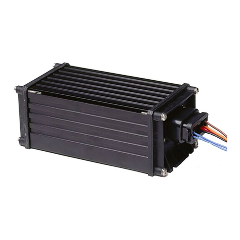
X-ECUTOR 2 Remote Amplifier
P2-8 WHT/BLK
WHT/BLU
P2-9
WHT/VIO
WHT/YEL
WHT/ORG
WHT/RED
WHT/BRN
WHT/GRN
RED/WHT
P2-4
P2-6
P2-7
P2-5
P2-2
P2-3
P2-1
RED
BLU
BLU
BLK
BRN
ORG
P1-6
P1-5
P1-3
P1-4
P1-2
P1-1
RADIO
RADIO
GROUND
+BATT
CONTROL
+
WHT/BLK 8
7
WHT/BLU
3
4
1
6
9
2
5
WHT/RED
WHT/VIO
WHT/YEL
WHT/ORG
WHT/BRN
RED/WHT
N/C
HEAD
+
BLK
WHT
WHT
BLK
SPEAKER
SPEAKER
100 WATT
100 WATT BRAKE
BATTERY
BLK2
WHT
GRY4
3
RED1
3 AMP
3 AMP
15 AMP
Wiring Option #2:Remote Switch Control
3 AMP
Momentary
Switch
No Connection
3 AMP
SPEAKER
100 WATT
+
BATTERY
P2-5
P2-6
P2-4
P2-3
P2-2
P2-1 RED/WHT
WHT/GRN
WHT/BRN
WHT/RED
WHT/ORG
WHT/YEL
CONTROL
HORN
VEHICLE
BUTTON
HORN
RELAY
WIRE
WHT/VIO
P2-7
WHT/BLK
P2-8
WHT/BLU
P2-9 MIC+
MIC-
PUSH TO TALK
AIRHORN
CONTROL 3
CONTROL 2
CONTROL 1
BRAKE
MANUAL
HEAD
HORN
7
8
9
3
1
4
5
2
6
+BATT
GROUND
P1-4 ORG
P1-3 BRN
P1-2 BLK
RED
P1-1
BLU
P1-5
BLU
P1-6
RADIO
RADIO
3
4
2
1
WHT
GRY
+BATT
CUT
RED
BLK
BRAKE
RED/WHT
N/C
WHT/BRN
WHT/RED
WHT/ORG
WHT/YEL
WHT/VIO
WHT/BLK
WHT/BLU
15 AMP
3 AMP
MAIN
BATTERY
SWITCH
+
100 WATT
SPEAKER
BLK
WHT
BLK
WHT
X-ECUTOR 2 Remote Amplifier
Wiring Option #1:Horn Ring Control
Installation:
1. Find a suitable mounting location. A dry, cool compartment is a good
choice.
2. Position the amplifier on the mounting location and using an awl or
similar tool, scribe the mounting surface where the mounting holes
are to be drilled.
CAUTION: As mounting will require drilling, it is absolutely
necessary to make sure that no other vehicle components could be
damaged by the drilling process. If any vehicle component could
suffer any potential harm, select a different location.
3. Carefully drill the mounting holes using a #30 drill bit.
4. Using the supplied sheet metal screws, secure the amplifier to its
mounting surface. IMPORTANT: The amplifier case must be
mounted or grounded to the vehicle chassis.
Input Connector - P1: Connecting to Power
WARNING: All customer supplied wires that connect to the positive
terminal of the battery must be sized to supply at least 125% of the
maximum operating current and fused “at the battery” to carry that load
(see wire chart next page).
1. Extend RED and BLACK wires to the main battery switch.
2. Connect the RED wire to one end of a fuse block.
3. Extend the wire coming from the fuse block to the main battery
switch as shown below (switch and fuse block are user supplied). Do
not connect this unit to the battery switch yet.
4. Connect the BLACK wire to the vehicle’s chassis ground.
Connecting to Speaker:
1. Route ORANGE and BROWN wires to speaker.
2. Connect ORANGE wire to the WHITE speaker wire.
3. Connect BROWN wire to BLACK speaker wire.
For dual speaker installation, connect the second speakers wires to the
same destinations as the first speakers wires, as shown below.
Connecting Radio Rebroadcast:
The two (2) remaining BLUE wires are used to connect your two-way
radio’s external speaker for radio re-broadcast. This is an optional
connection and will not effect the other operations. If radio rebroadcast
is not used, place dip switch 6 in the down position.
Note: Radio re-broadcast will NOT work with amplified remote
speakers! If your remote speaker is amplified (I.E.: contains a power
amp circuit in the speaker assembly), do not enable the radio re-
broadcast feature.
Installation will be complete after the fuse block wire is connected to the
main battery switch. After this connection has been made, visually
inspect the fuses at the back of the amplifier and at the battery. If either
of these fuses is blown, carefully inspect all of the circuit wires and
make sure they are wired correctly. Replace the blown fuses with ones
of an identical amp rating. If these fuses blow after installation or
activation, contact Whelen Engineering Technical Support.
NOTE: See next page for Adjusting Radio Rebroadcast.
See control head manual for connector P2 wiring.