Dimensions du produit
C
DE
A. 21SA_"(54,1 cm)
B. 30%" (77,1 cm) sur les modeles de 30" (76,2 cm);
36%" (92,3 cm) sur les modeles de 36" (91,4 cm)
C. Profondeur de 2%" (73 mm) de la bdte de brOleurs
D. Profondeur de 15%" (39,6 cm) du carter de ventilateur
E. Longueur du c_ble d'alimentation 3V2pi (106, 7 cm )
(installe a I'usine)
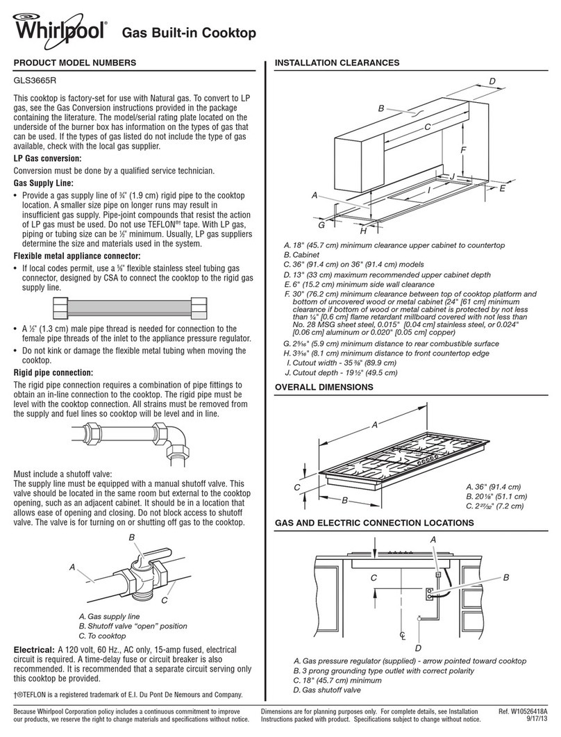
Dimensions de d_gagement
], A
F
A. 30" (76,2 cm) min. pour modeles de 30" (76,2 cm);
36" (91,4 cm) pour les modeles de 36" (91,4 cm)
B. Distance d'au moins 1" (25,4 mm) jusqu'au plus proche
materiau combustible depassant de 18" (45, 7 cm) au-dessus
de la table de cuisson
C. 29"/2" (74,9 cm) pour modeles de 30" (76,2 cm);
35½" (90,2 cm) pour modeles de 36" (9t,4 cm)
D. 21" (53,3 cm)
E. 1" (2,5 cm) de degagement minimum entre la paroi arriere et
le decoupage
F. Voir la REMARQUE* pour le degagement minimum entre la
table de cuisson et I'armoire sup_rieure.
*REMARQUE :D6gagement de s6paration minimum de
24" (61 cm) Iorsque le fond du placard en bois ou m6tallique est
prot6g6 par une plaque de 1/4"(6,4 mm) de mat6riau r6sistant aux
flammes recouverte d'uneplaque m6tallique d'6paisseur
appropriee (acier : calibre 28; acier inoxydable : 0,015" (0,4 mm);
aluminium : 0,024" (0,6 mm); cuivre : 0,020" (0,5 mm).
Degagement de s6paration minimum de 30" (76,2 cm) entre le
sommet de la table de cuisson et le fond non prot6ge d'un
placard de beis ou metallique.
Si I'installation d'une hotte est pr6vue au-dessus de la table de
cuisson, suivre les dimensions de d_gagement sp6cifi_es.
Degagement lateral : Un degagement minimum de 6" (15,2 cm)
entre le c6t6 de la table de cuisson et le mur lat6ral est
recommand6 pour une performance de ventilation maximum.
D6gagement arriere : Un degagement de %" (19,1 mm) entre le
bord arriere de la table de cuisson et lemur arri6re est
recommand&
D6gagement moteur/ventilateur : Un d6gagement de 2" (51 mm)
minimum entre le moteur et le placard est necessaire pour un
refroidissement convenable. Un d_gagement de 6" (15,2 cm) est
recommand_ pour permettre I'acc_s en cas de reparations.
Dimensions de d_coupage
B
/
D
A. 29½" (74,9 cm) pour modeles de 30" (76,2 cm);
35½" (90,2 cm) pour modeles de 36" (91,4 cm)
B. Profondeur de d#coupage de 21" (53,3 cm)
C. Choisir la configuration de d_coupage appropri_e
pour le passage des conduits. Voir "Installation
typique d'evacuation" pour les mesures.
D. Espace de 2" (5,1 cm) minimum au bord avant de
la table de cuisson
REMARQUE : Le plan de travail dolt servir de support & la table
de cuissen sur 3" (7,6 cm).
Dimensions minimum du placard inf6rieur
Largeur du placard inf6rieur 30" (76,2 cm)
Prefondeur du placard inf_rieur 24" (61 cm)
Profondeur du comptoir 25" (63,5 cm)
II est n6cessaire d'utiliser les dimensions d'ouverture du dessus
du comptoir indiquees. Les dimensions donnees sent les
degagements minimums de 0" (0 cm).
Preparation de I'ar6te du comptoir
Pour un mat_riau lamifie d6coratif, chanfreiner les ar_tes
expos_es pour 6viter d'_cailler le mat_riau lamifi& R6aliser les
arrondis sur les angles, et limer pour produire une ar6te lisse et
6viter toute fissuration.
10
