manuals.online logo
Brands
  1. Home
  2. •
  3. Brands
  4. •
  5. Whirlpool
  6. •
  7. Cooktop
  8. •
  9. Whirlpool RC8330XTW0 User manual

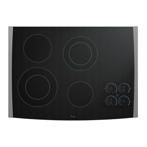
Whirlpool RC8330XTW0 User manual

IMPORTANT:
Read and save
these instructions.
IMPORTANT
Installer: Leave Installation Instructions
with the homeowner.
Homeowner: Keep Installation Instructions
for future reference.
Save Installation Instructions for local
electrical inspector’s use.
2089Volt,
30” Solid Element
Electric Built-in
Cooktop
PattNo.4?11880
Before you start...
Proper installation is your responsibility.
Make sure you have everyihing
necessary for correct installation.
The clearances specified are for
combustible walls and materials that
30” min. base
cabinet
is required. If Grounded electrical supply is reqwed
cabinet has a drawer, a 3-l/2” depth See ‘Electrical requirements-. Panel 8.
clearance from the countertop to the
top of the drawer (or other obstructton)
in base cabinet is required.
I
have a density of 20 or more pounds
per cubic foot. No evaluation of
clearances has been made for
installotlons adjacent to materials that
are less than 20 pounds per cubic foot
or10 plastic tiles and sheeting
Check location where
cookfop will
be installed. The location should be
away from strong draft areas, such as
windows, doors and strong
heCItIng
vents or fans. The cook-top should
be located for convenient use in
Counlertop opening dimensions
that are shown must be used
For new installations:
I
.--3*-l/2’
2&1/2’min.-
I
29-W’ max.
opening deplh:
IS-314’
min.-
20-!a’ “XIX.
2.718’ “I”. Ipace lo llO”l
edgo orcounlerlop
If cabinet has a drawer, a 3-l/2’
depth clearance from the counferop
to the top of the drawer (or other
obstruction cablnet) ISrequited
Electrical Shwzk Hazard
It is
Ihe cuslomer’s responsibilii:
l
To contacl a qualiied elecfrical
installer.
l
To assure Thai the eleclrical
insfallafion is adequaie and in
conformance with National
Electrical Code, ANSI/NFPA 70.
lalesi ediiion”. and all local
codes and ordinances.
:ailure to do x) could result in
ire, electrical shock or ofher
z=xwnal injury.
Personal Injury Hazard
Cabinet storage above Me cookin
UfOCe should be avoided. If
:abinels are already installed,
educe the hazard of reaching
wer a heated cocking surface
)y inslolling range hood.
he range hood should extend a
ninimum of 5 inches out horn the
mttom front of the cabinets.
leaching over a heated
:aoking surlace could result in a
erious burn.
Important:
Observe all governing codes and
ordinances. Failure to meet codes
and ordinances could lead to fire
or
electrical shock.
Tools needed for
installaticn:
Panel A
Electrical
requirements Electrical
connection
Electrical Shock Hazard
- Electrical ground is required on
this
appliance.
. Improper connection d the
equipment-grounding conductor
can resuli in electrical shock.
* Check with a qualified elechician
1 you are in doubt as lo whether
the appliance is properly
grounded.
. Do Not have a fuse in ihe neutral
or grounding circuil. A fuse in the
neutral or grounding circuii could
resull in electrical shock.
Failure lo follow these inslructions
could result in an elechicol shock
or other personal injury.
A.
A three-wire, three-phase, 208.voh.
KHz. AC only electrical supply
is required on a separate circuit.
fused on both sides of the line. A
time-delay fuse or circuit breaker is
recommended. The fuse size must
not exceed the circuit rating of the
appliance specified on the serial/
rating plate located on the bottom
of the cooktop box.
B
.
THE COOKTOP MUST BECONNECTED
WITH COPPER WIRE ONLY.
c.-
Wire sizes and connections must
conform to the requirements of the
National Electrical Code, ANSI/NFPA
70 - latest edition”. and all local
codes and ordinances.
Copies of the standard listed above
may be obtained from:
” National Fire Protection Associolion
Batlerymarch Park
Quincy. Massuchuselis 02269
D.
The appliance should be connected
directly to the fused disconnect (or
circuit breaker) through flexible.
armored or non-metallic sheathed,
copper cable. lXe flexible. armored
cable extending from
the
appliance
should be connected directly to the
junction box.
E.
Locate the junction box to allow as
much slack as possible between the
junction box and the appliance so
that the cookiop can be moved if
servicing is ever necessary Do Not
cut the conduit
Electrical Shock Hazard
. Electrical ground is required on
this appliance.
. This appliance must be
connected lo a grounded.
permanent wiring system or a
grounding connector should be
connected to the grounding
terminal or wire lead on Ihe
appliance.
. D&connect power lo the junction
box.
. Do Nol connect lo the electrical
supply until appliance is
permanently grounded.
Failure (0 do so could resuli in
electrical shock, serious injury.
or death.
This appliance is manufactured with a
frame-connected. green or bare,
grounding wire.
Connect the appliance cable to the
junction box through a U.L-listed
conduit connector.
Complete electrical connection
according to local codes and
ordinances.
A.
Where
local
codes permit connecting
the frame-grounding conductor to the
neutral (white) Junction box wire:
B.
Where local codes Do Not permit
connecting the frame-grounding
conductor to the neutral (white)
junction box wire:
Cable horn
power supply
JunctIonbox
Figure 2
1. Disconnect the power supply.
2. Connect the two black wires
together. Then connect the two red
wires together. Cap the unused white
wire. (See Figure 2.)
3. Connect the green or bare ground-
ing wire from the appliance cable to
a grounded wire in the junction box
or to o grounded. copper. cold water
pipe.“”
4. Do Not ground fo a gas supply pipe
or
hat water
pipe.
Do Not connect to
electrical supply until appliance is
permanentty grounded. (See Figure 3.1
““Grounded. cold water pips must have
metal conk&y to ele~tricol
ground
and not be intempted
by
plasHc.
rubber. or other elechkal l~ulating
connectors arch as hoses. filliros.
warners or golets (including &er
meteror oump). Any electrical
lnruloling connector should be jumped
OSshown with a kngm of No.-4 copper
wire securely clomped to bare
metal ot both ends
GaouNLlING CLAMP
toWe horn cooktop
Figure 1
copper
2. Connect the green (or bare)
appliance cable wire with the
neutral wire in the junction box.
3. Connect the two black wires
together. Then connect the two red
wires together.
(See Figure 1.)
grourdng
Figure 3
F.
A U.L.-listed conduit connector must
be provided at the junction box
Panel B
Now start...
With cooktop In kitchen.
till entire cookfop up from cutout
when repositioning cooktop in
countertop opening.
Failure lo
do so could scrafch 6 .
Assemble clomps.
Remove the shipping materials and
tape from the cooktop. Remove the
hardware package from the side
of the carton.
m I
Insert clamp flange into the slot in the
side of the burner box. Rotate other
end of clamp away from burner box
until clamp issecurely in place. Repeat
with the other clamp.
lnse; the cooktop into the countertop
opening. Center the cooktop in the
-cutoui Check that the front of the
cooktop isparallel to the front edge
of the countertop. Check that all
required clearances are met. Use a
pencil to outline the rear of the
cooktop on the countertop.
Do Not
overlighten screws.
Overtightening screws could
damage cookfop surface.
3.
Place two of the foam shipping pieces
on the countertop near the cutout.
Remove the cooktop from the cutout
and place it upside down on the
shipping pleCeS. \
Remove the paper backing from a
small section of the foam sealing strip.
Place the strip l/8’ from the crxktop
edge on the underside of the glass.
Continue until the foam strip
completely outlines the edge of
the cook-top.
5
lnsei the cooktoop into the cutout and
align ti with the pencil outline. Check
that the cooktop is parallel to the front
edge
of the countertop. lift the entlre
cooktop to make adjustments so the
foam sealing strip can seal properly.
Panel C
&e one hand to lightly press down on
the countertop above the clamp
screw Tighten the clamp screw by
hand. Do Not overtighten the screw.
Repeat with the other clamp screw.
9.
Make the electrical connection. (See
‘Electrical requirements’ and ‘Electrical
connection’ sections. Panels A and EL
for detah.)
10
. Turn on the power supply.
11.
Push in and turn each control knob to
the ‘HI* position Check the operation
of the cooktop heating elements and
Indicator lights
Numbers
to steds
,‘@@vicJed iri the Use andCare Guide
-... ,., .~

Other Whirlpool Cooktop manuals

Whirlpool RCS2012RS03 User manual

Whirlpool

Whirlpool RCS2012RS03 User manual

Whirlpool GLT3057RB01 User manual

Whirlpool

Whirlpool GLT3057RB01 User manual

Whirlpool WCC31430AW00 User manual

Whirlpool

Whirlpool WCC31430AW00 User manual

Whirlpool RC8536XT User manual

Whirlpool

Whirlpool RC8536XT User manual

Whirlpool RCS3004 User manual

Whirlpool

Whirlpool RCS3004 User manual

Whirlpool GJC3055 User manual

Whirlpool

Whirlpool GJC3055 User manual

Whirlpool WCE97US0HB01 User manual

Whirlpool

Whirlpool WCE97US0HB01 User manual

Whirlpool RCS2002RS03 User manual

Whirlpool

Whirlpool RCS2002RS03 User manual

Whirlpool GJD3044RB02 User manual

Whirlpool

Whirlpool GJD3044RB02 User manual

Whirlpool GLS3064R User guide

Whirlpool

Whirlpool GLS3064R User guide

Whirlpool YGR556LRKB0 User manual

Whirlpool

Whirlpool YGR556LRKB0 User manual

Whirlpool GLT3057 User manual

Whirlpool

Whirlpool GLT3057 User manual

Whirlpool KGCT055 User manual

Whirlpool

Whirlpool KGCT055 User manual

Whirlpool WCG55US0HB User manual

Whirlpool

Whirlpool WCG55US0HB User manual

Whirlpool RCS2012RS00 User manual

Whirlpool

Whirlpool RCS2012RS00 User manual

Whirlpool 4454652 User manual

Whirlpool

Whirlpool 4454652 User manual

Whirlpool KECC568RPS User manual

Whirlpool

Whirlpool KECC568RPS User manual

Whirlpool GLT3657RB02 User manual

Whirlpool

Whirlpool GLT3657RB02 User manual

Whirlpool SC8636EB User manual

Whirlpool

Whirlpool SC8636EB User manual

Whirlpool RC8700ED User instructions

Whirlpool

Whirlpool RC8700ED User instructions

Whirlpool W10162212A User manual

Whirlpool

Whirlpool W10162212A User manual

Whirlpool AKT 302 User manual

Whirlpool

Whirlpool AKT 302 User manual

Whirlpool Ceran GJC3654RS03 User manual

Whirlpool

Whirlpool Ceran GJC3654RS03 User manual

Whirlpool GJD3044RB00 User manual

Whirlpool

Whirlpool GJD3044RB00 User manual

Popular Cooktop manuals by other brands

Viking M0908F60094G brochure

Viking

Viking M0908F60094G brochure

Daniela DAN2GTS user manual

Daniela

Daniela DAN2GTS user manual

Toastmaster TMDO1200 Specifications

Toastmaster

Toastmaster TMDO1200 Specifications

hestan KICS30 installation manual

hestan

hestan KICS30 installation manual

Frigidaire FGC30S4HWA installation instructions

Frigidaire

Frigidaire FGC30S4HWA installation instructions

Roper Gas Cooktops installation instructions

Roper

Roper Gas Cooktops installation instructions

Wolf CT36EU Specifications

Wolf

Wolf CT36EU Specifications

KitchenAid Architect K6CP462K installation instructions

KitchenAid

KitchenAid Architect K6CP462K installation instructions

Ellrona Comfort plus 2000 SC operating manual

Ellrona

Ellrona Comfort plus 2000 SC operating manual

St George CC29/E Operation manual

St George

St George CC29/E Operation manual

Sencor SCP 5405WH user manual

Sencor

Sencor SCP 5405WH user manual

Optimum PK-1560 operating instructions

Optimum

Optimum PK-1560 operating instructions

Frigidaire FEC30S6D Factory parts catalog

Frigidaire

Frigidaire FEC30S6D Factory parts catalog

Glen GL 3078 user guide

Glen

Glen GL 3078 user guide

KitchenAid KECC567GAL2 parts list

KitchenAid

KitchenAid KECC567GAL2 parts list

Cosmo COS850SLTX-E user manual

Cosmo

Cosmo COS850SLTX-E user manual

Electrolux 318 200 687 Use and care guide

Electrolux

Electrolux 318 200 687 Use and care guide

KitchenAid KECC501GBL3 parts list

KitchenAid

KitchenAid KECC501GBL3 parts list

manuals.online logo
manuals.online logoBrands
  • About & Mission
  • Contact us
  • Privacy Policy
  • Terms and Conditions

Copyright 2025 Manuals.Online. All Rights Reserved.