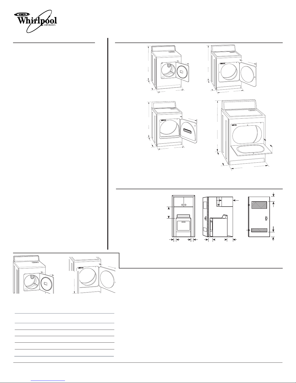
29" (73.7 mm) Gas Dryer
PRODUCT MODEL NUMBERS PRODUCT DIMENSIONS
RECESSED AREA AND CLOSET INSTALLATION
EXHAUST VENTING
B caus Whirlpool Corporation policy includ s a continuous commitm nt to improv
our products, w r s rv th right to chang mat rials and sp cifications without notic .
Dim nsions ar for planning purpos s only. For compl t d tails, s Installation
Instructions pack d with product. Sp cifications subj ct to chang without notic .
R f. W10150630
07/2009
223/4"
(578 mm)
433/8"
(1100 mm)
*273/4"
(705 mm) 29"
(736.6 mm)
29"
(736.6 mm)
*26"
(660 mm)
433/8"
(1100 mm)
151/4"
(387.4 mm)
433/8"
(1100 mm)
*273/4"
(705 mm)
29"
(736.6 mm)
223/4"
(578 mm)
433/8"
(1100 mm)
29"
(736.6 mm)
*273/4"
(705 mm)
133/4"
(349 mm)
A R d
ABC
18"*
(457 mm)
1"
(25 mm)
29"
(736.6 mm)
1"
(25 mm)
1"*
(25 mm)
14" max.*
(356 mm)
27¾"
(705 mm)
5"*
(127 mm)
48 in.
(310 cm )
2
*
2
24 in.
(150 cm )
2
*
2
3"*
(76 mm)
3"*
(76 mm)
For clos t installation
with a door, minimum
v ntilation op nings in
th top and bottom of
th door ar r quir d.
Louv r d doors with
quival nt v ntilation
op nings ar acc ptabl .
1. S l ct th rout that will provid th straight st and most dir ct path outdoors. Plan
th installation to us th f w st numb r of lbows and turns. Wh n using lbows or
making turns, allow as much room as possibl . B nd v nt gradually to avoid kinking.
Avoid 90° turns.
2. D t rmin v nt l ngth.
Th maximum l ngth of th xhaust syst m d p nds upon:
• Typ of v nt (rigid m tal or fl xibl m tal).
• Numb r of lbows us d.
• Typ of hood.
S th xhaust v nt l ngth chart that match s your hood typ for th maximum v nt
l ngths you can us .
3. D t rmin th numb r of lbows you will n d.
IMPORTANT: Do not us v nt runs long r than sp cifi d in th V nt L ngth Chart.
In th column listing th typ of m tal v nt you ar using (rigid m tal or fl xibl m tal),
find th maximum l ngth of m tal v nt on th sam lin as th numb r of lbows.
Number of
90 turns
or elbows
Type of
vent
Box or
Louvered
hoods
Angled
hoods
0Rigid metal 64 ft (20 m) 58 ft (17.7 m)
154 ft (16.5 m) 48 ft (14.6 m)
244 ft (13.4 m) 38 ft (11.6 m)
335 ft (10.7 m) 29 ft (8.8 m)
427 ft (8.2 m) 21 ft (6.4 m)
Rigid metal
Rigid metal
Rigid metal
Rigid metal
o
Gas supply: Dry r is quipp d for us with
Natural gas. Dry r can b conv rt d to L.P. gas.
Wh n rigid pip is us d it should b 1/2"IPS. Wh n
acc ptabl to th gas suppli r and local cod s, 3/8"
approv d aluminum or copp r tubing may b us d
for l ngths und r 20 ft (6.1 m). For l ngths mor
than 20 ft (6.1 m), larg r tubing and a diff r nt siz
adapt r fitting should b us d. Pip -joint compounds
r sistant to th action of L.P. gas must b us d. Do
not us TEFLON®†tap . If local cod s p rmit, it is
r comm nd d that n w fl xibl m tal tubing, d sign-
c rtifi d by CSA, b us d for conn cting th
applianc to th rigid gas supply lin . (Th gas pip
which xt nds through th low r r ar of th
applianc has 3/8"mal pip thr ad.) An individual
manual shutoff valv must b install d within 6 ft
(1.8 m) of th dry r in accordanc with th National
Fu l Gas Cod ANSI Z223.1.
Ele tri al: A 120-volt, 60-Hz, AC-only, 15- or
20-amp, fus d l ctrical supply is r quir d. A tim -
d lay fus or circuit br ak r is r comm nd d. It is
r comm nd d that a s parat circuit s rving only
this dry r b provid d.
Exhaust venting: Exhaust your dry r to th outsid .
4" (10.2 cm) diam t r h avy m tal xhaust v nt and
clamps must b us d. DURASAFE™ v nting products
ar r comm nd d. For b st drying p rformanc , rigid
m tal v nts ar r comm nd d. Fl xibl m tal v nts ar
acc ptabl only if acc ssibl for cl aning. Do NOT us
plastic or m tal foil v nt. Exhaust outl t hood must b
at l ast 12" (30.5 cm) from th ground or any obj ct
that may b in th path of th xhaust.
†®TEFLON is a r gist r d trad mark of E.I. Du Pont D
N mours and Company.
A. Small Opening
Side-Swing Door
B. Large Opening
Side-Swing Door
A. Recessed area
B. Side view - closet or confined area
C. Closet door with vents
C. Wide Opening
Side-Swing Door
D. Wide Opening
Hamper Door
AB
C
D
NOTE: Sid and bottom xhaust installations hav a
90º turn insid th dry r. To d t rmin maximum
xhaust l ngth, add on 90º turn to th chart.
433/8"
(1100 mm)
151/
(387.4 mm)
*R quir d spacing
*Most installations r quir a minimum 5" (127 mm) cl aranc
b hind th dry r for th xhaust v nt with lbow.
WGD5000V
WGD5100V
WGD5200V
WGD5300V
WGD5600V
WGD5700V
WGD5790V


