manuals.online logo
Brands
  1. Home
  2. •
  3. Brands
  4. •
  5. Whirlpool
  6. •
  7. Oven
  8. •
  9. Whirlpool RB275PXV1 User manual

Whirlpool RB275PXV1 User manual

ELECTRICBUILT-IN
(STARTING WITH 1982 MODELS)
Part No. 311509 Rev. B
l-1/4” MIN.
L
6”
HOLE IN 0’
SUPPORT S
FOR CABLI
JUNCTION BOX:
SEE NOTE 1
*FOR A 36” OPEN TOP OVEN
DOOR HEIGHT **2B-l/2” MINIMUM
IF 2&5/B” IS AVAILABLE
THE CUTOUT SHOULD BE
MADE 2&5/0”
FIGURE 1 - Rough-In Dimensions
1. CARPENTRY
Refer to Figure
1
for the dimensions of the oven and the
space necessary to receive the oven. The oven support
surface may be solid plywood or similar material but the
contact surface must be level from side to side and from
front to rear. This surface is 2%” below the open door
height.
NOTE 1: The oven support surface must be flush with the
bottom of the cabinet cut out.
WARNING: TO AVOID DAMAGE TO CABINET
AND/OR POOR BAKE PERFORMANCE, DO NOT
BLOCK OVEN VENT.
EN
RFACE
3” MAX.
NOTE: Wire sizes and connections must conform with the
fuse size and rate of the appliance in accordance with the
National Electrical Code and local codes and ordinances.
Do not use an extension cord.
B. The appliance should be connected to the fused discon-
nect (or circuit breaker) box through flexible armored or
non-metallic sheathed cable. The flexible armored cable
extending from the appliance should be connected directly
to the junction box. The junction box should be located
as shown in Figure 1 so that as much slack as possible
remains in the cable between the box and the appliance
so that it can be moved if servicing is ever necessary.
C. A suitable strain relief must be provided to attach the
flexible armored cable to the junction box.
2. ELECTRICALREQUIREMENTS
D. Electrical Connection.
IMPORTANT: OBSERVEAU GOVERNINGCODES
AND ORDINANCES
SAVE THESE INSTRUCTIONS FOR THE LOCAL
ELECTRICAL INSPECTOR’S USE
A. A three-wire or four-wire single phase 120/240 volt 60Hz
AC only electrical supply (or threewire or four-wire 1201206
volt if specified on nameplate) is required on a separate
circuit fused on both sides of the line (time-delay fuse or
circuit breaker is recommended). Do NOT fuse neutral. The
fuse size must not exceed the circuit rating of the appliance
specified on the nameplate.
It is the personal responsibility and obligation of the
customer to contact a qualified installer to assure that the
electrical installation is adequate and is in conformance
with the National Electrical Code and local code
ordinances.
Electrical ground is required on this appliance.
This appliance is equipped with copper lead wires. If the
connection is made to aluminum house wiring, use only special
connectors which are approved for joining copper and
aluminum wires, in accordance with the National Electrical
Code and local codes and ordinances.
This appliance is manufactured with a white neutral power
supply wire and a frame-connected green ground wire.
2
1. If local codes permit connection of the frame-
grounding conductor to the neutral (white wire),
connect the green and white wire from the supply
cable of the appliance together and to the neutral
(white) wire in the junction box. Connect the remain-
ing wires from the supply cable, matching the colors,
to the wires in the junction box.
2. If local codes DO NOT permit frame grounding to the
neutral, separate the white and green wires that
extend out of the end of the supply cable of the
appliance. Connect the white wire from the supply
cable to the neutral wire in the junction box.
Connect the black and red wire from the supply cable,
matching the colors, to the corresponding wires in the
junction box. The green wire MUST now be used to
ground the appliance in accordance with local electri-
cal codes. Connect the green ground wire to a
grounded cold water pipe*or to the grounded lead in
the service panel. Do not ground to a gas supply pipe.
Do not connect to electrical power supply until
appliance is permanently grounded. Connect the
ground wrre before turning on the power. See Figure
2.
CAUTION - If connecting to a four-wire electrical system
(MOBILE HOME) the appliance frame MUST NOT be
connected to the neutral wire of the four-wire electrical
system. Separate the white and green wires that extend
out of the end of the supply cable of the appliance.
Connect the white, red and black wires from the supply
cable, matching the colors, to the corresponding wires in
the junction box. Connect the green wire from the supply
cable to the ground wire in the junction box.
COPPER
GROUND WIRE GROUNOEO COLD
WATER PIPE
(REMOVE PAINT ETC.1
GROUND CLAMP
(MUST BE TIGHT
ON PIPEj
FIGURE2
*Cold water pipe must have metal continuity to electrical
ground and not be interrupted by plastic, rubber or other
electrically insulating connectors (including water meter
or pump) without adding a jumper wire at these connec-
tions.
4. INSTALLATION
NOTE:
Before installing the oven in the cutout, it may be helpful to
remove the oven door. See details below.
Inset-t appliance into cut-out. Screws are provided for fasten-
ing the front frame of the appliance to the cabinet. The moun-
ting holes in the front frame of appliance may be used as a
template to locate the appliance mounting screw holes.
CAUTION: For your personal safety, and to minimize
potential personal injury, this oven must be securely
fastened to the cabinet, using the four screws that are
provided.
Use caution when mounting oven in cutout so you do
not over-tighten screws and cause porcelain chippage
or puncture oven cavity.
TO REMOVEOVEN DOOR
SELF-CLEANINGMODELS- LOWEROVEN DOOR
ONLY
(Door to be removed for installation only).
1. Remove the two screws, one on each side of the inner door
panel. See View A.
SCREW VIEW A
WARNING: UNDER DO CIRCUMSTANCES ARE THESE
DOOR TO BE INTERCHANGED.
3
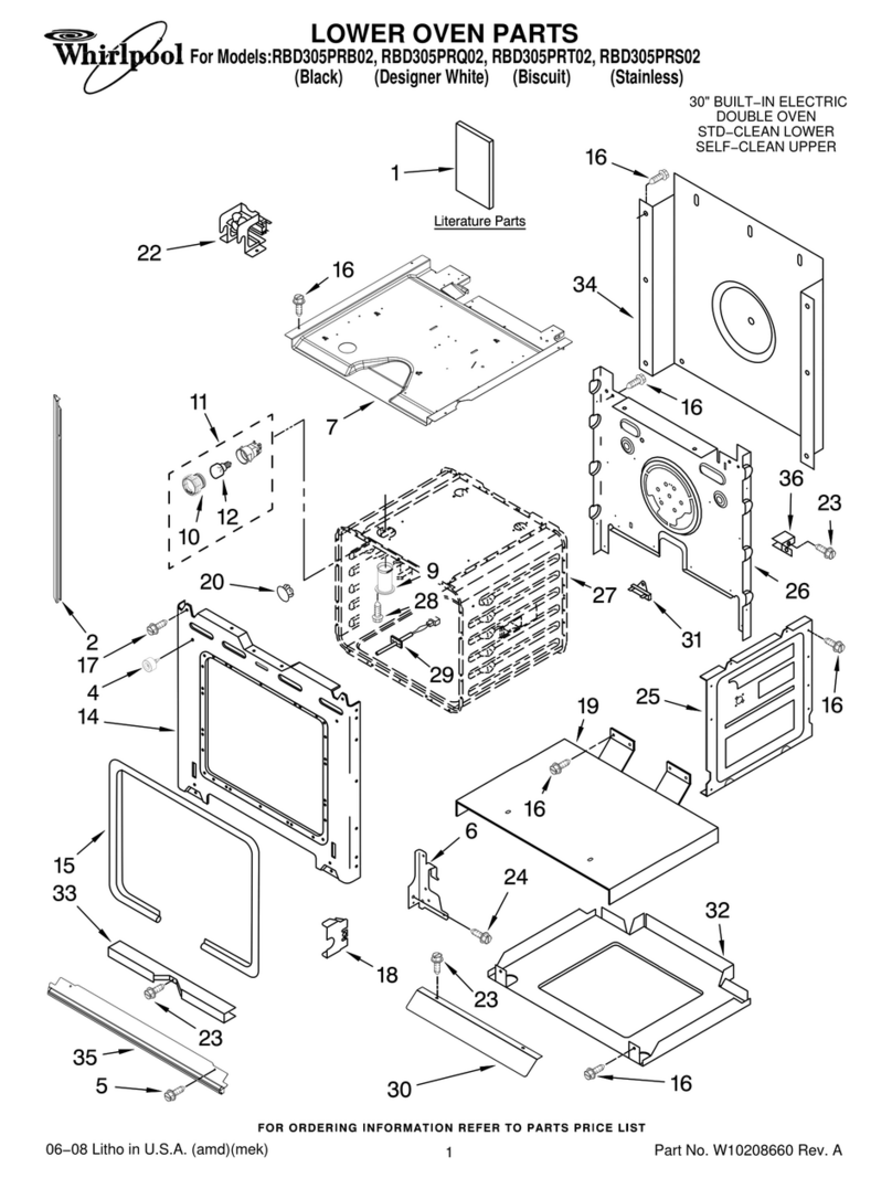
2. Put an allen wrench (5/32” or smaller) or equivalent in the
hole in each of the hinges. Close the oven door until the
pins touch the oven front. See View B.
3. The oven door can now be lifted off.
4. Reinstall oven door the same as on non-self cleaning models
(see below).
5. Reinstall the door mounting screws
VIEW
B
TO REMOVE OVEN DOOR (LOWER OVEN DOOR
SELF CLEANING MODELS, BOTH OVEN DOORS
NON SELF CLEANING OVEN MODELS).
Pull straight with the
angle 01 part-open door. Push down evenly.
Removing the oven door: (For installing and cleaning)
Removing the oven door may make it easier to clean the
oven. To remove the door, first open it to the first stop
(about 4 inches orlOcm).Take hold of both sides of the
door near the top; then lift it at the same angle it is in.
With the door off, you will notice how the ends of the
hinges slide into slots at the bottom corners of the door.
To put the door back on, fit both bottom corners of the
door over the ends of the hinges. Push the door down
evenly, so neither corner gets ahead of the other. When it
reaches the bottom, you can close the door. A safety
latch will hold the door open until it is on correctly.
5. CHECKING
CAUTION: Do not touch the elements. They may be hot
and you may get burned.
A. THERMOSTAT
1. Broil - Turn selector switch to BROIL and set
thermostat to a high temperature position. The
top element should become cherry-red and the
indicator light should glow.
2. Bake - Turn selector switch to BAKE and set
thermostat to 350”. The bottom element should
become red and the indicator light should glow.
B. CLOCK
Refer to the Use and Care Guide for proper operation of
the clock.
C. ROTISSERIE (if optional kit has been installed)
1. Position the spit bar on special rack.
2. Insert point of spit bar into hole in the back of the
oven.
3. Rotation starts upon insertion of spit bar.
In rhe event your WHIRLPOOL appliance should need serwce. call the dealer from whom You
purchased the appliance or a WHIRLPOOL lranchlsed TECH-CARE@serwce company He IS I” the
Yellow Pages of Your telephone d,rectorY l,sted under Washers, DrYers-Rap?,-wg or Serwng
You can also oblaln his name and number by dlalmg. free. wthm the contmenlal United States
(except Alaska) ths Whirlpool COOL-LINE@‘Serwce (800) 253.1301 [when calhng from Mlchlgan.
dial (800) 632.2243; from Alaska or Hawav. dwl (800) 253-11211 CM just as you normally doal
long distance A special operator wll tell You the name and number of Your nearest Whirlpool
TECH-CARE sew~ce oudet Durmg normal working hours. Whtrlpool consultants at th,s same
number WIII also answer any questfons about operating or mamtatnmg your apphance not covered
I” your Operat,ng InStr”CtlO”s
Learn the benefnts of us~na TECH-CARE serwce for rna,ntannnwa the auahtv or~a~nallv bull1 Into
your WHIRLPOOL apphanc;
- ..-.
_.... -. -^^. -^----_-.-.. --_.--_. .._--^- __.^...^_.. _^^^_
Wl-llHL~UUL CUli~UliAI IUN UtN ILJN HA~BUti, MILHltiAN 4YlJZZ
Part No. 311509
Rev. B
4

Other Whirlpool Oven manuals

Whirlpool GW395LEPB01 User manual

Whirlpool

Whirlpool GW395LEPB01 User manual

Whirlpool W9OS24S1P User manual

Whirlpool

Whirlpool W9OS24S1P User manual

Whirlpool AKZ661IX User manual

Whirlpool

Whirlpool AKZ661IX User manual

Whirlpool AKZ 210/01 Dimensions

Whirlpool

Whirlpool AKZ 210/01 Dimensions

Whirlpool RBS305PR User manual

Whirlpool

Whirlpool RBS305PR User manual

Whirlpool SB100PER User manual

Whirlpool

Whirlpool SB100PER User manual

Whirlpool AKZ9 9480 NB User manual

Whirlpool

Whirlpool AKZ9 9480 NB User manual

Whirlpool RS610PXGN1 User manual

Whirlpool

Whirlpool RS610PXGN1 User manual

Whirlpool AKP 241/05 User manual

Whirlpool

Whirlpool AKP 241/05 User manual

Whirlpool AKZM 6570 Operating instructions

Whirlpool

Whirlpool AKZM 6570 Operating instructions

Whirlpool AKZM 755 User manual

Whirlpool

Whirlpool AKZM 755 User manual

Whirlpool GBS277PDQ User manual

Whirlpool

Whirlpool GBS277PDQ User manual

Whirlpool G2P 61F User manual

Whirlpool

Whirlpool G2P 61F User manual

Whirlpool AKP 619/IX/01 User manual

Whirlpool

Whirlpool AKP 619/IX/01 User manual

Whirlpool JennAir JJW6024HM User manual

Whirlpool

Whirlpool JennAir JJW6024HM User manual

Whirlpool BIK9 PP8TS2 PT CH User manual

Whirlpool

Whirlpool BIK9 PP8TS2 PT CH User manual

Whirlpool AKZM 657/IX User manual

Whirlpool

Whirlpool AKZM 657/IX User manual

Whirlpool AMW 595 IX User manual

Whirlpool

Whirlpool AMW 595 IX User manual

Whirlpool OMK58HR0X User manual

Whirlpool

Whirlpool OMK58HR0X User manual

Whirlpool W10045000 User manual

Whirlpool

Whirlpool W10045000 User manual

Whirlpool W7 OM4 4BS1 H User manual

Whirlpool

Whirlpool W7 OM4 4BS1 H User manual

Whirlpool AKG 659/IX User manual

Whirlpool

Whirlpool AKG 659/IX User manual

Whirlpool AKZM 8910 Operating instructions

Whirlpool

Whirlpool AKZM 8910 Operating instructions

Whirlpool W10045010 User manual

Whirlpool

Whirlpool W10045010 User manual

Popular Oven manuals by other brands

Vulcan-Hart CB1824E Installation & operation manual

Vulcan-Hart

Vulcan-Hart CB1824E Installation & operation manual

Quincy lab Bench 21-250ER operating manual

Quincy lab

Quincy lab Bench 21-250ER operating manual

Zanussi ZOU 594 user manual

Zanussi

Zanussi ZOU 594 user manual

Russell Hobbs 26095 instructions

Russell Hobbs

Russell Hobbs 26095 instructions

Fisher & Paykel OB60NC Series installation instructions

Fisher & Paykel

Fisher & Paykel OB60NC Series installation instructions

Comfee CO-F25A1 instruction manual

Comfee

Comfee CO-F25A1 instruction manual

Miele H 348 B2 operating instructions

Miele

Miele H 348 B2 operating instructions

Maytag MEW5527DDB Dimensions

Maytag

Maytag MEW5527DDB Dimensions

hestan KSO Series use and care manual

hestan

hestan KSO Series use and care manual

American Range AROFG-30 Installation, use & care manual

American Range

American Range AROFG-30 Installation, use & care manual

Sears WB44K5013 installation instructions

Sears

Sears WB44K5013 installation instructions

Blodgett BCX-14G Installation operation & maintenance

Blodgett

Blodgett BCX-14G Installation operation & maintenance

Gram IO 20662-92 X instruction manual

Gram

Gram IO 20662-92 X instruction manual

Kernau KBO 0972 SVPT B user manual

Kernau

Kernau KBO 0972 SVPT B user manual

KitchenAid KEBS277DBL4 parts list

KitchenAid

KitchenAid KEBS277DBL4 parts list

Gorenje BOC 6322 AX User instructions

Gorenje

Gorenje BOC 6322 AX User instructions

SEVERIN TOASTOFEN MIT UMLUFT TO 2036 datasheet

SEVERIN

SEVERIN TOASTOFEN MIT UMLUFT TO 2036 datasheet

GE JKS06 owner's manual

GE

GE JKS06 owner's manual

manuals.online logo
manuals.online logoBrands
  • About & Mission
  • Contact us
  • Privacy Policy
  • Terms and Conditions

Copyright 2025 Manuals.Online. All Rights Reserved.