ROSTEC LMA8 User manual

LMA8 Mic/Line Preamplifier
0
ROSTEC LMA8
8-channel Professional Mic/Line Preamplifier
Revision 5, March 23, 2016

LMA8 Mic/Line Preamplifier
1
General description
Contents………………………………………………………..…. 1
Features ………………………………………………………..... 2
General description ……………………………………………… 2
Inputs and outputs……...........................……………………… 2
Insert points……………...........................……………………… 2
Simplified signal flow............................................................... 3
Operational description
Instrument/line inputs........……….……................................... 4
Insert points ………...….……................................................... 4
+48 V Phantom Voltage………………….………….................. 4
Input gain adjust..............………………….…………................ 5
Status indicators……………….……………………………........ 5
Mic inputs..............................................................................…6
Line outputs ………………………..……………….................... 6
Direct inputs ……….............................................................…. 7
Digital interface slot............................………...………….……..7
Remote ground connection..................................................….8
Front and back panel quick guide.......………...……………….. 9
Mechanical and electrical specifications ……………..……10
Technical section
Clipping characteristics............. ……………………………..... 11
Impulse response....................................................................11
Unwanted HF feedback...........................................................12
Noise performance and crosstalk............................................13
Classical distortion analysis....................................................15
FFT distortion analysis............................................................17

LMA8 Mic/Line Preamplifier
2
Features
•8 microphone inputs at the back panel
•8 high impedance instrument inputs at the front
•8 balanced line outputs at the back panel
•8 balanced insert points at the back panel
•Insert points are selectable from the front panel
•Switching done by sealed gold contact relays
•Ultra low noise
•Ultra low distortion
•+30 dBu input headroom
•Automatic switching between instrument input
and mic input
•Exceptionally open and transparent sound
•Input circuit has vacuum tube characteristics
•True balanced architecture throughout the unit
•Smooth gain adjustment from +10 dB to +70 dB
by potentiometer, no clicks
•Built-in +48 Volts Phantom Power
•Linear low noise power supply. No Swichmode!!
•Slot for optional USB or AES digital interface.
•Inputs and outputs are ESD protected to 23 kV,
IEC 61000-4-2 and 15 A surge, IEC 61000-4-5.
•Sturdy steel metal casing, electrically and
magnetically screened.
•Stand-alone desktop or with mountable 19” rack
mount flanges
•Affordable price.
General description
The LMA8 is an 8 channel ultra low noise and ultra low
distortion mic/line preamplifier designed with the
professional sound engineer in mind. The unusual large
input headroom of +30 dBu enables the amp to handle
fast transient and large dynamic sound pressure
changes with ease. At the same time it reproduces
micro-details and environmental depth perspective with
a natural openness and impressive accuracy.
The circuit is designed so input clipping cannot be
experienced. The input circuit has a clipping limit at
+30 dBu, and because there is always at least +10 dB of
gain in the signal path, the output (or the connected
equipment) will simply always clip before the input.
The LMA8 is a purist's dream come true. The design is
based on a very stringent philosophy, meaning the
shortest possible signal path and the highest possible
quality components. The input circuit is a true class A
differential gain stage, and it has a transfer characteristic
that resembles that of a vacuum tube triode, giving the
unit a natural, relaxed and open sound, yet it maintains
an extremely fast and totally precise response.
The architecture is fully balanced throughout the unit,
which means that the signals between the various
circuits are routed as a positive and a negative signal,
not the standard way of using signal and ground. Ground
is not used to transfer audio signals at all. This
architecture keeps the audio path free from non-linear
distortion from currents running in the ground mesh or
from “non musical” signals from external electrical fields,
power supply noise, crosstalk from other channels etc.
Although the LMA8 is constructed by using modern
day's cutting edge technology, the design philosophy is
inspired by some of the very best preamps that have
been manufactured over the last 50 years.
The basic model is pure analog, aimed at the
professional studios that already have high quality AD
and DA converters available
Optional USB or AES interface modules are available,
using top range digital converters with ultra low distortion
and 120 dB dynamic range
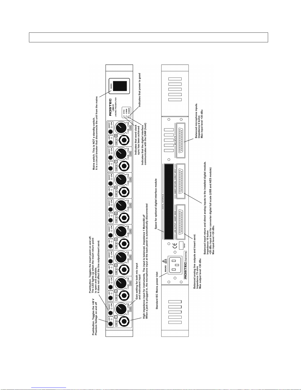
Mic inputs and instrument/line inputs
The amp has 8 separate and identical channels. Each
channel has two inputs, a microphone input and a high
impedance line/instrument input.
The 8 microphone inputs are placed at the back panel
and use one 25 pin D-SUB female connector
The 8 instrument/line inputs are placed at the front panel
for easy access and use 1/4" standard Jack connectors
Switching between line input and mic input is automatic.
When no Jack is plugged into the front connector, the
mic input at the back is active. When a Jack is plugged
into the front connector, the unit disables the mic input at
the back, activates the line input at the front, and
switches to high impedance mode. The high impedance
of the line input (1 Mohm/60 pF) is intended for
instruments, like guitar or bass, but it is equally well
suited for line level equipment, such as keyboards and
the like.
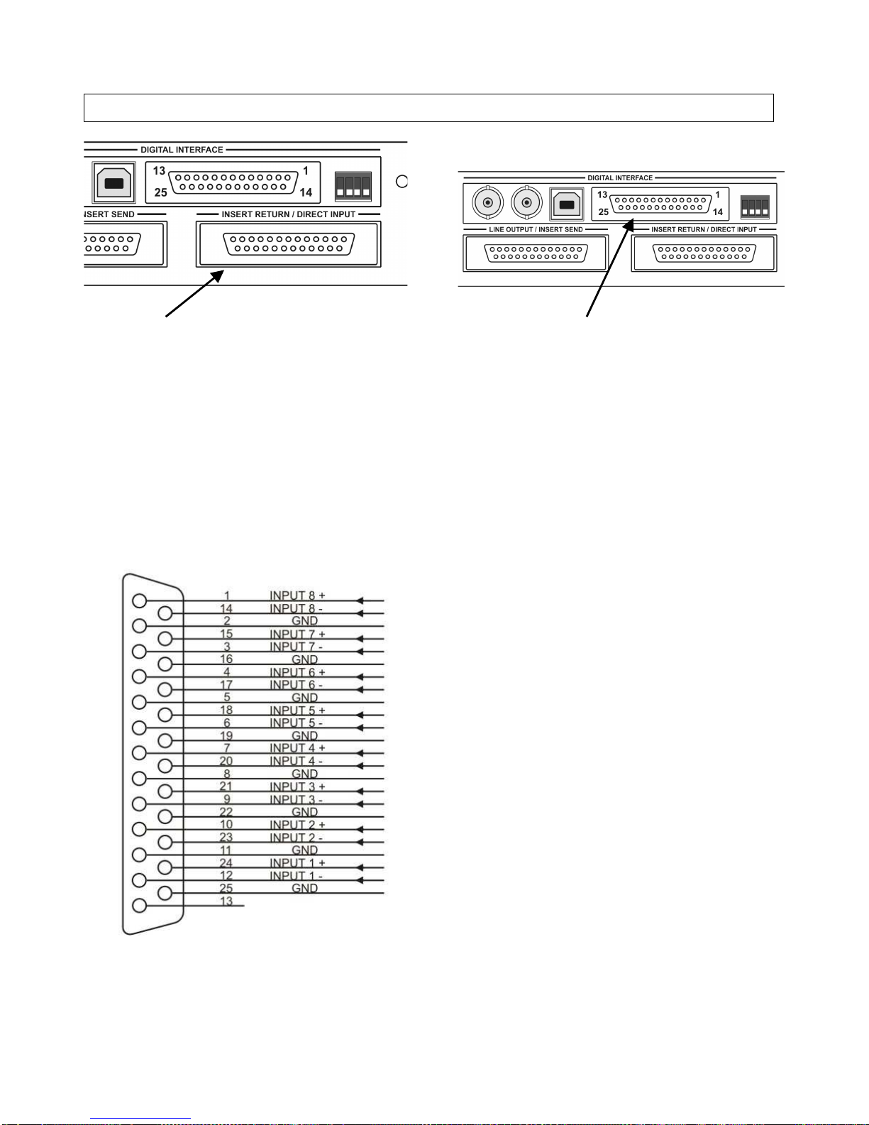
Outputs and insert point
Each channel has a buffered balanced line output and a
balanced direct input to the digital modules. Each use
25 pin D-SUB female connectors at the back panel.
The 8 line outputs and the 8 direct inputs form the insert
points, intended for use with analog equipment. These
insert points can be bypassed by pressing the insert
point switches at the front panel.

LMA8 Mic/Line Preamplifier
3

LMA8 Mic/Line Preamplifier
4
Operational description
Instrument/line input
Each channel has a ¼" Jack instrument/line input on the
front panel. The input is for use with instruments (like
guitar, bass etc) and it can be used in a balanced as well
as an unbalanced configuration.
When a Jack is plugged-in, the input circuit automatically
disconnects the mic input, switches to high impedance
mode and activates the line input.
Plugging in a mono Jack enables the normal unbalanced
input configuration.
Plugging in a stereo Jack enables the balanced input
configuration.
For further information about using the balanced
configuration see page 8, Remote ground connection
Insert point switch
The toggle switch controls the bypass function of the
insert point. The insert point exists electrically between
the output of the preamp and the input of the digital
module.
When the LED is ON, the signal chain between the
preamp and the digital module is “open” which means
that external equipment can then be inserted between
line output/insert send and the insert return/direct input.
When the LED is OFF, the signal is routed directly from
the preamp to the digital module. The insert return/direct
input is then inactive.
The line output/insert send is not affected, and is always
active
When no digital module is installed, the switch has no
function. Pressing the switch will momentarily turn the
LED on, but the LED will automatically turn off again
after 2 seconds.
+48V Phantom Voltage
The toggle switch turns the Phantom Voltage at the mic
input on and off. The LED indicates the status.

LMA8 Mic/Line Preamplifier
5
Input gain adjust
Turning the knob controls the input gain from minimum
to maximum in one smooth movement. No clicks and no
jumps. It works for both instrument/line input and
microphone input.
The gain range is +10 to +70 dB from input to the line
output on the D-SUB connector at the back.
Status indicators
These LEDs are status indicators for the digital interface
module (USB or AES) and for Power Good.
SYNC indicates a solid lock to the incoming word clock.
COMM indicates a good communication link to the DAW
POWER indicates that power is on
The indicators should be steady on during normal
operation. When no digital module is installed, only the
POWER LED is active.

LMA8 Mic/Line Preamplifier
6
Analog inputs (mic inputs)
The analog input D-SUB connector is for the microphone
inputs. The maximum input is +30dBu. The input
impedance is 6 kohm
The 25 pin D-SUB connector follows the TASCAM
standard as shown below.
Observe that channel 8 is at the beginning of the pin
numbers and channel 1 is at the end.
It seems a little awkward, but it is the reigning industrial
standard. Following this standard makes it easier to
interface with off-the-shelf cables to other multi channel
equipment, like AD/ DA converters, mixing consoles etc
Analog outputs (line outputs)
The analog output D-SUB connector is for the balanced
line outputs. The output buffers are of industrial grade
transformerless balanced floating configuration. For
unbalanced operation, the negative output must be
shorted to ground
Maximum output is +30 dBu in balanced mode.
Maximum output is +24 dBu in unbalanced mode.
The 25 pin D-SUB connector follows the TASCAM
standard.

LMA8 Mic/Line Preamplifier
7
Direct input
The analog input D-SUB connector is for the balanced
direct line inputs to any installed digital module.
With no digital module installed, the connector is inactive
The inputs are electronically balanced. For unbalanced
operation, the negative input should be shorted to
ground.
The input impedance is 10 kohm
Maximum input is +30 dBu in balanced mode.
Maximum input is +24 dBu in unbalanced mode.
The 25 pin D-SUB connector follows the TASCAM
standard.
Digital interface slot
This is the slot for the optional digital interface module,
shown here with the USB module installed
The interface module is installed by opening op the box
and fastening the module with screws and connecting it
with ribbon cables.
The procedure is simple and straight forward for a
qualified technician. It is described in the technical
manuals for the USB and AES modules.

LMA8 Mic/Line Preamplifier
8
Remote ground connection
The balanced instrument/line input of the LMA8 opens up the unique possibility to use a pseudo balanced configuration
with instruments like guitar, bass etc. The configuration will cancel out a large portion of the electrical noise induced in the
cables. This is quite advantageous when using long cables on stage or in an electrically noisy environment near light
dimmers or near high power mains installations.
A guitar or bass hook-up is a high impedance system, and as such, it is very sensitive to electrical interference. Using a
balanced cable instead of a single core cable, introduces one additional wire to "receive" the environmental noise. This
additional noise signal is fed into the balanced input of the LMA8 at the negative input terminal, canceling out the noise
signal at the positive terminal without affecting the sound signal from the instrument.
The configuration will in most cases give a substantial noise reduction, depending on the electrical characteristics of the
instrument pick-up. The two signal lines are terminated by different impedances at the instrument and at the preamp input,
so a total noise cancellation will not take place. As a minimum, a noise reduction of at least 10 - 15 dB should be
expected.
Note that the noise from the instrument pick-up is not reduced. Only the noise induced into the cable is affected.

LMA8 Mic/Line Preamplifier
9
Front and back panel quick guide

LMA8 Mic/Line Preamplifier
10
Mechanical and electrical specifications
Dimensions with rack mounts: Width 19 inch, height 1U (44 mm), depth 210 mm
Dimension as desktop: Width 420 mm, height 42 mm, depth 210 mm
Weight: 5.0 kg
Power: 180 - 253 VAC, 50-60 Hz, 15 Watts
ESD: Protected to 23 kV, IEC 61000-4-2 and 15 A surge, IEC 61000-4-5
Mic input impedance: 6 kohm
Line input impedance: 1 Mohm/60 pF
Max input level balanced, mic or line: +30 dBu
Max input level unbalanced, line: +24 dBu
Max input level balanced, direct input: +30 dBu
Max input level unbalanced, direct input: +24 dBu
Max output level, balanced output: +30 dBu
Max output level, unbalanced output +24 dBu
Gain, input to balanced output: +10 dB to +70 dB
Input noise: -134 dBu (A weighted, 22 Hz - 22 kHz)
Input noise: -131 dBu unweighted
Frequency response: 5 Hz - 200 kHz, +/- 0.1 dB
Crosstalk: -120 dB, 20 Hz - 20 kHz, input terminated by 150 ohm
Distortion, + noise, classical analysis:
THD+N 0.00035 % @ 1 kHz, 10 dB gain
THD+N 0.00075 % @ 1 kHz 30 dB gain
Distortion, FFT analysis:
THD 0.00014 % @1 kHz, 10 dB gain
THD 0.00014 % @1 kHz, 20 dB gain
THD 0.00015 % @1 kHz, 30 dB gain
THD 0.00024 % @1 kHz, 40 dB gain
THD 0.00046 % @1 kHz, 50 dB gain
THD 0.00092 % @1 kHz, 60 dB gain

LMA8 Mic/Line Preamplifier
11
Technical section
Clipping characteristics
The LMA8 shows excellent clipping characteristics. When the amp clips, there is no bouncing, ringing, pumping etc. There
is just regular and plain clipping. A closer look at the cutting edge of the clip can be seen on the right picture. Notice that
there is no overshoot and no recovery delay. There is only instant clipping and instant release.
This kind of clipping is barely audible on short transients. Note that the output level is +30 dBu, so most equipment
connected to the amp have already gone into clipping at this level
The input clipping always occurs at a 10 dB higher level than the output clipping, thus the input clipping is always masked
by the output clipping. Input clipping cannot be transferred to the output.
Impulse response
The above snapshots show the ideal step impulse response of the LMA8. When subjected to at steep transient (in this
case a step impulse with 5 nsec rise time), there is no ringing and no overshoot. There is only total control. The amp does
NOT produce any signal itself when subjected to transient material. It does not add anything. It stays true to the source!
A closer look at the leading edge of the step impulse can be seen on the right picture. There is absolutely no ringing or
overshoot. Also, the amplitude of the step on the picture equals +20 dBu audio level, yet the circuit does NOT go into slew
rate mode. The curve remains a true exponential.
The output voltage swings 20 Volts in less than 1 usec. Rise time (10/90 % of the amplitude) is approx 600 nsec

LMA8 Mic/Line Preamplifier
12
Unwanted HF feedback and oscillation in studio installations
It may seem risky to install a piece of equipment witch exhibits such fast speed and high gain at the same time in a studio
environment. Normally, when the input signal path and output signal path of a amplifier with high gain and high frequency
response passes too close to each other, high frequency oscillation may occur.
This usually happens if the signals are routed through a mixing console of inferior quality, a bad patch-bay or through a
piece of equipment with bad crosstalk performance.
But not to worry; LMA8 has a mechanism in place to prevent such unwanted HF feedback.
HF oscillation in complex studio installations is prone to occur when both gain and frequency response is high. The LMA8
uses a well established technique that employs a "constant gain/bandwidth product" function. In short; it works by
reducing the upper frequency response when the gain is increased. The numbers below illustrates this:
Gain: +10 dB Upper frequency response (-0.1 dB) 200 kHz
Gain: +20 dB Upper frequency response (-0.1 dB) 153 kHz
Gain: +30 dB Upper frequency response (-0.1 dB) 130 kHz
Gain: +40 dB Upper frequency response (-0.1 dB) 90 kHz
Gain: +50 dB Upper frequency response (-0.1 dB) 47 kHz
Gain: +60 dB Upper frequency response (-0.1 dB) 24 kHz
The change of the frequency response is not audible and it does not affect the internal gain structure, noise figure or
distortion figure.

LMA8 Mic/Line Preamplifier
13
Noise performance and crosstalk
Input noise
The graph shows the spectral density of the input noise by measuring with a sweeping 1/3 octave bandpass filter across
the audio range.
The input was terminated by 150 ohms and the gain was set to max (+70 dB)
The noise spectrum is linear and smooth from 1 kHz and up and exhibits the typical characteristics of white noise.
Below 1 kHz, the 1/f corner noise is dominant. A noise component from the power supply can be seen at 100 Hz at a level
of approx. -148 dBu
The rms sum of the noise from 22 - 22 kHz is -134 dBu A weighted, or -131 dBu unweighted.

LMA8 Mic/Line Preamplifier
14
Crosstalk
The graph shows crosstalk between adjacent channels. A +16 dBu signal was sent to channel 1, gain setting +10 dB. The
output level of channel 1 was +26 dBu.
The input of channel 2 was terminated by 150 ohms, and the signal level was measured at the output of channel 2.
The graph shows virtually no crosstalk below 100 Hz, which indicates that there is no transfer of audio signals due to
signal dependent ground currents
The crosstalk increases moderately at higher frequencies, but it is still below -120 dBu at 20 kHz. This indicates a small
capacitive audio signal transfer internally between components.
Channel 1 is blasting at +26 dBu and channel 2 sees only -120 dBu at the input. This clearly demonstrates the benefits of
a true balanced architecture.

LMA8 Mic/Line Preamplifier
15
Classical Distortion Analysis
The standard analysis of distortion in audio circuits has traditionally been "Total Harmonic Distortion + Noise".
This method has only limited usefulness in this case, because the distortion of the LMA8 is so low, that it is masked by
noise at higher gain settings.
The LMA8's input noise is among the lowest today's technology can offer, and the distortion of the unique input amplifier
circuit is so low, that it can only be quantified by classical analysis at lower gain settings. At higher gain settings, a FFT
analysis is required.
Distortion + noise at +10 dB gain
The THD+N is below 0.0004 % in the whole audio range. The measured THD+N result shows good linearity from 20 Hz to
20 kHz; only a slight increase above 2 kHz is seen.
The input noise contribution at +10 dB gain corresponds to a level of approx. 0.00007 %.
Thus it can be seen that the graph mainly represents the distortion of the circuit.

LMA8 Mic/Line Preamplifier
16
Distortion + noise at +30 dB gain
The THD+N is below 0.0008 % in the whole audio range. The measured THD+N result is very close to linear from
20 Hz - 20 kHz
The input noise contribution at +30 dB gain corresponds to a level of approx. 0.0007 %.
The distortion of the circuit is still below 0.0004 %.
Thus it can be seen that the graph mainly represents the noise of the circuit.
Increasing the gain setting further has little effect on the distortion figure, but will only add noise to the measurement.

LMA8 Mic/Line Preamplifier
17
FFT distortion analysis
FFT analysis has the ability to detect distortion that is buried in the noise. Noise is a statistical phenomenon, and by
reading several samples and adding them together, the FFT analysis is able reduce the noise to its average value, thus
revealing the distortion components otherwise buried in the noise.
Below are plots of the distortion characteristics at various gain settings. Distortion levels are listed for 2nd to 10th
harmonic and are quantified in dBFs. As a guideline, 120 dBFs equals 0.0001 %, 140 dBFs equals 0.00001 %
Gain +10 dB, frequency 1 kHz. The rms sum of all distortion components (THD) is 0.00013 %

LMA8 Mic/Line Preamplifier
18
Gain +20 dB, frequency 1 kHz. The rms sum of all distortion components (THD) is 0.00014 %

LMA8 Mic/Line Preamplifier
19
Gain +30 dB, frequency 1 kHz. The rms sum of all distortion components (THD) is 0.00015 %
Other manuals for LMA8
2
Table of contents
Other ROSTEC Amplifier manuals