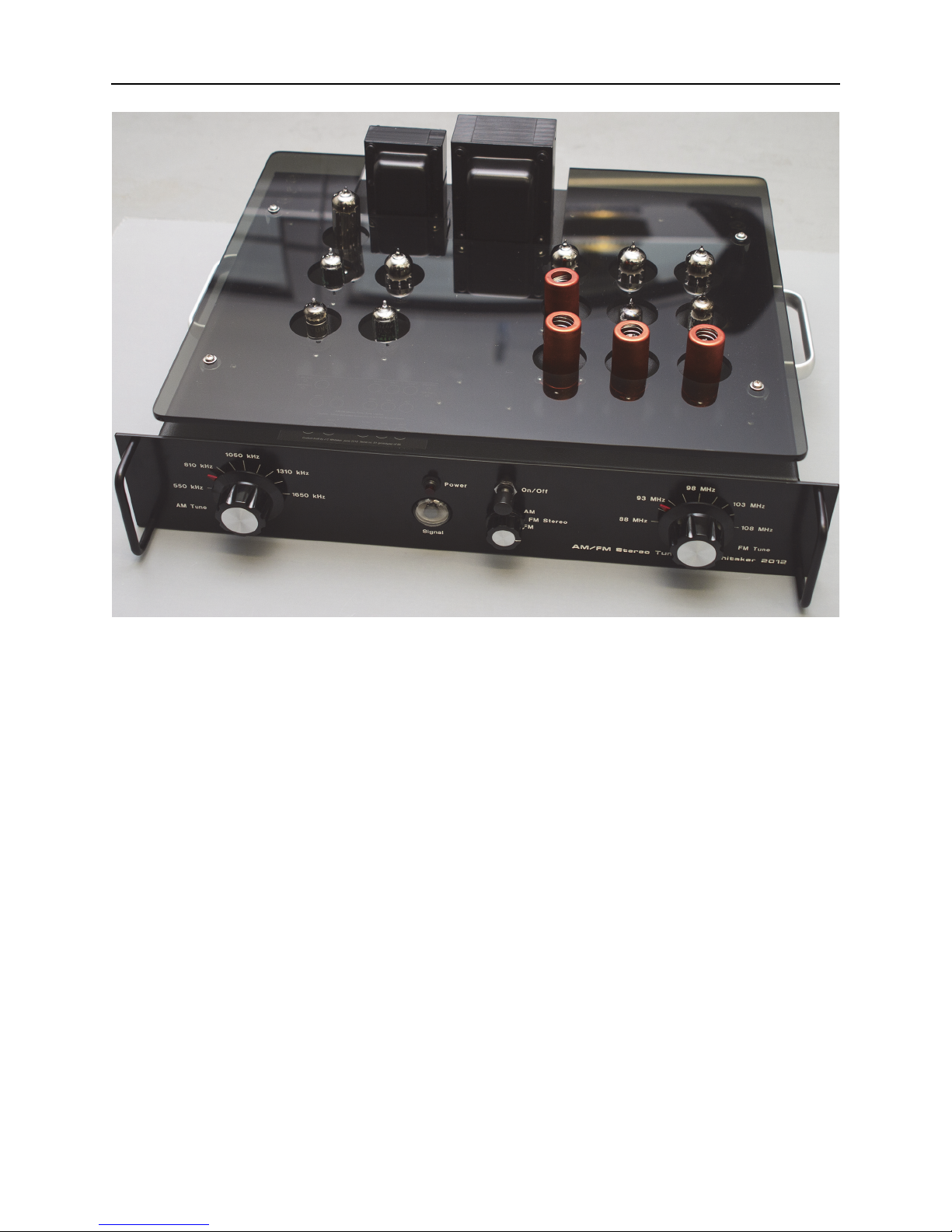
WhitakerAudio AM/FM Stereo Tuner 2012 Manual

WhitakerAudio
AM/FM Stereo Tuner
User and Assembly Manual

Copyright 2015 WhitakerAudio LLC, Morgan Hill, California, USA.
No part of this document may be reproduced without the express written consent of
WhitakerAudio.
Specifications subject to change without notice.
Any trademarks used in the manual are the property of their respective owners.
Note:
This document is intended to assist readers in building an audio product for personal use. No
warranties are expressed or implied. Always use good engineering practices and appropriate
safety precautions.

Table of Contents
1 Circuit Description 10
1.1 AM Tuner/Power Supply Circuits 10
1.2 FM Tuner/Multiplex Circuits 16
1.2.1Multiplex Section 20
2 Parts List 23
3 PWB Design 32
4 Construction Techniques 37
5 Step-by-Step Instructions 39
5.1 Assembly of the AM Tuner/Power Supply PWB 40
5.2 Assembly of the FM Tuner/Multiplex PWB 53
5.3 Chassis and Final Assembly 70
5.3.1Front Panel Components 70
5.3.2Back Panel Components 72
5.3.3Cable Clamps and Related Hardware 74
5.3.4Install Chassis-Mounted Transformers 76
5.3.5Install Chassis Components 77
5.3.6Install Printed Wiring Boards 79
5.3.6.1 AM Tuner PWB 79
5.3.6.2 FM Tuner PWB 80
5.3.7Wire the Transformer Leads 82
5.3.7.1 Cable Organization 82
5.3.7.2 Power Transformer Leads 83
5.3.7.3 Choke Leads 84
5.3.8AM Tuner PWB Auxiliary Connections 84
5.3.9FM Tuner PWB Auxiliary Connections 88
5.3.10Chassis-Mounted Controls 88
5.3.11Primary Power Connections 91
5.3.12PWB Interconnections 94
5.3.13Audio Cabling 95
5.4 Final Assembly Check 100
6 Initial Checkout 103
6.1 Troubleshooting 117
6.1.1Tuner Completely Inoperative 117
6.1.2Oscillation 119
6.1.3Hum and Noise 119
6.1.4Excessive Drift 119
6.1.5Low Sensitivity 119
7 Setup and Alignment 120
7.1 AM Section 120
7.1.1AM Alignment Steps 122
7.2 FM Section 127
7.2.1FM Tuner Alignment 128
7.2.2Multiplex Section 131

7.3 Final Touches 135
8 Installation 137
8.1 AM Section 137
8.1.1Assembly of the Loop Antenna 138
8.1.2Tuning Guidelines 139
8.2 FM Section 139
8.2.1Tuning Guidelines 140
9 Troubleshooting Guidelines 142
9.1 Safety Considerations 142
10 Tube Characteristics and Data 144
10.16AL5 144
10.26BA6 145
10.36BE6 147
10.46BQ7 149
10.56C4 150
10.66CA4 151
10.76CB6 153
10.86E5 154
10.96U8 Pentode/Triode Tube 156
10.1012AU7 157
10.11Notes 158

AM/FM Stereo Tuner
The AM/FM Stereo Tuner is a high-quality device intended for discriminating listening. The
product features quality components throughout. The tuner is available either as a kit or
assembled as a part of the signature series of WhitakerAudio products. This tuner shares the
craftsmanship and impressive industrial design of the other offerings in the WhitakerAudio line.
This tuner, like the other products, is limited in number.
Overview specifications:
• Tube AM/FM tuner, with mono and FM stereo outputs
• High-quality components and construction throughout
• Sensitive AM section featuring wide audio bandwith performance
• Classic FM section with sensitive front end
• Magic Eye tuning indicator for visual response of tuning condition
• Separate AM and FM tuning controls
• 6:1 tuning gear reduction for accurate tuning

6
WhitakerAudio
• Front panel switchable output (AM, FM mono, FM stereo)
• Output impedance 100 k ohms at 1 V rms
• Conservatively rated components used throughout
• Soft-start power supply to extend component life
• Over-temperature sensor to protect against component failure
• Power requirements: 117 V ac, 60 Hz, 110 W nominal.
• Physical dimensions: 19-in wide by 16-in deep by 7-in high. Note that the depth
specification does not include back panel cables.
• Weight approximately 25 lbs.
Extensive shielding is provided on the FM tuner PWB to optimize performance and prevent
parasitic oscillations.
The tuner is built using all new components, with the exception of the tuning capacitors and
RF coils. These devices are no longer manufactured and therefore must be harvested from old
sets. In all cases, the devices have been carefully restored and inspected to meet new-old-stock
performance levels.
The AM tuner is based on a classic Heathkit design. The basic circuit, originally offered for
sale in the 1960s, is designed to provide wide frequency response in order to enjoy the capabilities
of the radio stations of the day. The AM tuner is capable of flat response up to 9 kHz and with
wide-range program sources, the effect was quite similar to FM of the day. A small amount of
high frequency pre-emphasis is employed to provide additional “brilliance” to the higher
frequency sounds, thus giving the illusion of greater range than actually present.
The AM tuner is designed to provide for optimum performance when tuned to strong signals
from local stations and powerful clear channel stations located within a reasonable distance from
the receiving point. Weak signals are problematic when it comes to high fidelity listening since
the programming cannot be enjoyed for long due to the noise and interference from adjacent
stations. Therefore, sensitivity is not intended to be a key feature of the receiver, although it is
relatively high. Careful attention has been given to selectivity and 10 kHz inter-station whistle
rejection so that maximum benefit can be obtained from strong stations. An electrostatically
shielded external loop antenna is employed for improved performance in noisy locations. A built-
in rod antenna may be used for locations where strong signals are present.

7
AM/FM Stereo Tuner
Regrettably, few AM radio stations broadcast music programming today, let alone with a
focus on high fidelity. Nonetheless, the tuner is built to be true to the design of the time and
provide the wide AM frequency response capability that the original designers intended. The fact
that stations do not take advantage of high fidelity capabilities is just a sidebar.
Some metropolitan locations have many stations located nearby, some at frequencies close
together and almost equal signal strength. In these cases, sideband interference is likely to be
troublesome. This problem can be overcome by antenna orientation, since the external loop
antenna is sharply directional on the null.
A wide-band AM tuner has an entirely different tuning feel than a conventional tuner, the
response and noise quieting remaining much the same over a wide tuning range. Perfect tuning is
accomplished by setting the dial midway between the band edges; an improvement in high
frequency response will probably be noted at this point.
The FM section also builds upon a classic 1960s Heathkit design. Most commercial high-
fidelity FM tuners of the 1960s conformed to a particular circuit configuration and therefore
offered similar performance figures. This tuner is a bit different in that a ratio detector is used.
The ratio detector is capable of excellent performance and has the advantage of being self-AM-
limiting, eliminating the need for multiple limiter stages. An advantage is gained by not using
limiters, since the “limiting threshold” is eliminated. Weak FM stations cannot overcome this
threshold and so are heard highly distorted and/or with high background noise. Performance of
the ratio detector is quite good on weak stations that are received at a signal strength roughly
equivalent to the specified sensitivity of the tuner. Of course, noise levels will rise with very poor
signals, but the accompanying distortion does not occur until the signal becomes too weak to be
useful. The major disadvantage of the ratio detector is that the audio output is dependent on signal
strength to some extent. This is a trade-off the original designers felt was worthwhile.
High-gain tubes are used in the IF and mixer stages of the FM tuner to give high sensitivity
and to aid the detector in its function. A high gain, low noise cascade type RF amplifier is used for
the same reason, as well as to isolate the local oscillator from the antenna. Loading and pulling of
the oscillator by the antenna circuit is minimized in this manner and external radiation from the
oscillator is substantially reduced.

8
WhitakerAudio
Sensitivity of the FM tuner is high enough that satisfactory performance will be obtained with
an indoor antenna made up of 300 Ω twin lead, if reasonable signal strength is prevalent in the
area. Best fringe performance will be obtained with an outdoor type of antenna.
The tuner is built around two main printed wiring boards (PWBs), engineered for top
performance. A ground plane covers the component side of each PWB. Component placement
and board traces have been engineered to minimize hum and noise. The boards feature a unique
mounting technique for the vacuum tubes used in each tuner that keeps heat away from the PWB
and minimizes hum in the unit.
The PWBs are engineered to reduce off-board connections, thereby simplifying layout and
providing for controlled characteristics from one unit to the next. The power supply is integrated
on to the AM receiver board and uses a full wave rectifier tube feeding a choke and followed by a
high-capacity bank of filter capacitors. The PWBs include top and bottom solder masks and top-
side silk-screened legends.

9
AM/FM Stereo Tuner
The decision to design the AM/FM Stereo Tuner around classic Heathkit designs from the
1960s is a recognition of the high-quality tube circuits of that era. It is also a recognition of the
realities of finding the necessary parts to build a tube-based tuner today. Key components of this
tuner have been repurposed from old tube tuners because the parts are simply not available today
as new components. The parts in question are the tuning capacitors and radio frequency (RF) coils
and transformers. Regrettably, such devices are no longer manufactured for tube-based systems
and the choice of new-old-stock (NOS) components is exceedingly limited. Fortunately, there
remains a supply of old (typically non-functioning) radios to serve as a source of spare parts.
(These sources, regrettably, will not last forever, of course.)
Shields are provided for four tubes in the FM tuner section. While not strictly required, they
are recommended. The photos on the this page show the tuner with and without the shields.
The AM/FM Stereo Tuner is intended for appointment listening. Turn it on and dial-in your
favorite station. Enjoy audio as it should be heard.

10
WhitakerAudio
1 Circuit Description
The circuit description is divided into two sections: 1) the AM tuner, power supply, and related
circuits, and 2) the FM tuner and multiplex circuits.
1.1 AM Tuner/Power Supply Circuits
A schematic diagram of the AM receiver section is shown in Figure 1.1. 1
The AM tuner is a five tube superheterodyne receiver employing high-gain tubes and
carefully designed coils in all RF circuitry. Careful layout of components and leads allows this
high-gain to be realized without instability.
Two types of antenna inputs are used for installation flexibility. A low impedance, external
multi-turn loop may be used that provides high sensitivity with good noise immunity and broad
directional characteristics. Very low impedance circuits are not sensitive to electrostatic noise, but
allow efficient transfer of electromagnetic RF signals. Proper impedance matching to the RF
amplifier grid is obtained by use of a large secondary-to-primary winding ratio. An electrostatic
type of antenna input is also provided, which couples a high-impedance straight wire type of
antenna to the RF amplifier grid circuit directly through a coupling capacitor. A much smaller
antenna can be used where necessary, but with poorer noise rejection. Along these lines, a rod
antenna is provided, which may be used in areas of high signal strength.
A 6BA6 tuned radio frequency (TRF) amplifier (V1) is used ahead of the oscillator/mixer
stage (V2) to increase the overall gain and to reduce coupling between the antenna and oscillator
circuits. Signals picked up by the antenna are coupled to antenna coil T1 through either the low-
or the high-impedance windings. This coil is tuned to give maximum gain at the desired signal
frequency and to attenuate all other signals as much as possible. RF energy from the coil is
coupled directly to the control grid of V1 and amplified. An output signal is taken from the plate
of the 6BA6 and delivered to the primary winding of the inter-stage (mixer coil) T2, where it is
inductively coupled to the grid circuit of the V2 6BE6 mixer and tuned once again to further
increase gain and selectivity.
1. The description of the AM tuner section and Figure 1.1 are adapted from: Heathkit: “Assembly and Operation of the Heathkit
Broadcast Tuner Model BC-1A,” the Heath Company, Benton Harbor, MI,

11
AM/FM Stereo Tuner
Figure 1.1 Schematic diagram of the AM tuner section.

12
WhitakerAudio
Note that the 6BE6 (V2) has five grids, a plate, and a cathode from which the name heptode
converter is derived. The first and second grids along with the cathode comprise a triode, which is
employed as a Hartley oscillator. A tuned circuit is connected between the first grid and ground,
with the cathode connected to a tap on the coil near the ground end, thus providing feedback to
maintain oscillation. The B+ voltage is connected to the #2 and #4 grids, which are tied together
internally within the tube. The #2 grid becomes a plate for the triode section and the #4 grid a
screen grid for the pentode section, containing the cathode, the #3 control grid, the #5 suppressor
grid, and the anode (plate).
Signals from the V1 RF stage are amplified again at the V2 6BE6 mixer stage, along with
another signal coming from the oscillator contained in this same stage. Since the oscillator and RF
signals are both present in the tube, they mix in such a manner that the sum and difference of the
two frequencies are present at the output of the mixer, as well as the RF and oscillator signals. The
oscillator frequency is selected so it is always 455 kHz higher than the tuned frequency of the RF
section. Therefore, the difference will always be 455 kHz. It is to this frequency that the
intermediate frequency (IF) transformers are tuned. This function of changing frequencies is the
well-known as the Superheterodyne Principle. Improved selectivity and gain is obtained due to
the fixed-tuned IF transformers, which are designed to provide optimum performance at one
frequency only.
RF energy from the plate of the mixer is coupled through the first IF transformer (T3) to the
grid of the 6BA6 IF amplifier (V3), where the 455 kHz difference (intermediate frequency) is
amplified. The first IF transformer will pass the 455 kHz signal and reject almost all others. The
amplified IF signal is taken from the plate of the 6BA6 (V3) to the second IF transformer (T4),
where residual signals are further reduced.
Amplitude modulation consists of a carrier frequency that is heterodyned or mixed with the
audio modulating frequency at the transmitter, producing four frequencies of which three are
transmitted. A similar function takes place in the V2 6BE6 mixer in that the carrier frequency will
be present along with the sum and difference of the carrier and audio, called sidebands. The audio
signal, per se, is not transmitted. Rather, the sideband distance on each side of the carrier
frequency is determined by the audio frequency—higher modulating frequencies spreading the
sidebands farther apart. Sideband power is determined by the percentage of modulation, with 50
percent of additional power present in the sidebands at 100% modulation, the fundamental power

13
AM/FM Stereo Tuner
remaining the same as with no modulation. The additional 50 percent sideband power is furnished
by the transmitter modulator. Since sideband power and amplitude varies with modulation
percentage, the term amplitude modulation is applied.
Although AM could conceivably be a high-fidelity service, it normally is not for three primary
reasons.
• First, broadcast frequency allocations in the U.S. (and elsewhere) are 10 kHz apart. As
such, sidebands from each station must be limited to 5 kHz on each side of the carrier in
order to prevent interference with the next channel, unless the station has relatively clear
channels on each side, or employs a protective field pattern to prevent interference.
• Second, the dynamic range of the program material is limited. Modulation by the station
over 100% will result in spurious emissions and must be prevented. A limiter is used to
compress louder peaks, with a resultant loss of dynamic range.
• Third, the medium-frequency band in which AM broadcast stations operate exhibits a high
level of man-made noise, which limits the minimum noise floor.
Detection of AM signals can be accomplished by removing one half of the modulated carrier
envelope by rectifying the carrier in some manner, usually by employing a non-linear
unidirectional current device such as a vacuum tube or solid state diode. RF energy remaining
after detection is removed in a low pass filter that attenuates high frequency energy but passes
audio signals with little loss.
An unconventional type of detector is used in this AM tuner, although the basic principle of
operation is much the same as the more conventional single diode type described above. As
shown in Figure 1.1, two diodes (D1 and D2) are employed in a voltage-doubler circuit connected
to the secondary of second IF transformer T4. One diode is connected between the IF transformer
and ground and serves the normal function of rectifying or detecting one peak of the IF signal,
storing the developed negative dc voltage across a 47 pF capacitor (C18) also connected between
the IF transformer and ground. This diode conducts during the positive portion of the IF signal.
Because the positive portion of the signal is shorted to ground through the diode, only the
negative portion will be available to charge the capacitor—the diode appearing as an open circuit
to a negative potential. When a negative swing takes place, diode D1 connected between IF
transformer T4 and the filter will conduct, allowing the negative voltage to appear at the filter
input. Both diodes develop a negative voltage and these voltages add to yield twice the dc

14
WhitakerAudio
potential that would be provided by a single diode type of detector (as well as twice the
demodulated audio voltage). Symmetrical loading is maintained on the IF amplifier, for
conduction occurs on both peaks of the IF carrier, thus reducing non-linearity and resultant audio
distortion. Another advantage is gained in that the IF ripple frequency is doubled from 455 kHz to
910 kHz allowing more effective filtering of the IF signal, with less high frequency audio loss.
Most of the residual IF energy remaining after detection is bypassed to ground through the
series combination of C17/C18 (47 pF) connected between R17 (33 kΩ) and ground. Detected
audio and the remaining IF energy is passed through R17 where the rest of the IF ripple is
bypassed to ground through C19 (100 pF). Values of resistance and capacitance in this circuit are
carefully chosen to provide maximum attenuation of high frequency signals (RF and IF) while
passing audio up to 10 kHz with low loss.
Any detector can function only as well as the signal applied to it. If sidebands are suppressed
in the RF or IF system of a receiver, the resultant audio response will be suppressed in the same
manner. The IF signal in a superheterodyne receiver is an exact duplicate of the incoming RF
signal, the only change being the carrier frequency. Carrier and oscillator frequencies are
removed at the first IF stage, only the difference frequency and the original sidebands being
passed.
Audio from the detector circuit is coupled from the filter output through C20 (0.01 μF) to a
network of two 1 mΩ resistors (R20, R21) and a 150 pF capacitor (C21). These resistors are
arranged so that only one half of the audio voltage is applied to the grid of the V4 12AU7 tube at
audio frequencies of 1 kHz and lower. At higher frequencies, C21 begins to bypass some of the
audio signal around the attenuating resistor, causing a gradual rise in audio output from 1 kHz up
to 10 kHz to compensate for broadcast station roll-off at high audio frequencies. The first half of
V4 is a conventional triode amplifier and boosts the compensated signal applied to the grid by a
factor of about ten. The output from the V4a plate is connected to the 10 kHz whistle filter (T5),
commonly known as a bridged-T filter. Other frequencies are passed with little attenuation and so
only a sharp notch appears in the response.
Audio from the whistle filter is connected to output level control R24, which is then applied to
the grid of V4a through C26. The second half of the 12AU7 is connected as a cathode follower to
provide a low-impedance output from the AM tuner circuit.

15
AM/FM Stereo Tuner
Automatic volume control (AVC) action is obtained by feeding the negative dc voltage
developed at the voltage-doubler detector (D1/D2) back to the grid circuits of V1, V2, and V3. A
filter comprised of R10/C7 and R11/C13 remove audio components from the AVC voltage buss.
The dc output from this network is proportional to the incoming signal strength and so is useful as
a gain controlling voltage. AVC is applied to the grid circuit of V2 from R10/C7. AVC bias for
V1 is taken from the same point but through another filter of R1/C1 to provide isolation between
the two stages. Again, the voltage is applied to the grid through the antenna coil, with signal
return provided by C1. AVC control voltage for the V3 is reduced by the voltage divider R11/R12
and C13. Reduced AVC is desirable in the IF amplifier to keep the stage operating in a more
linear fashion, thus reducing distortion. Because the AVC voltage from the voltage-doubler
detector is approximately twice that obtained with other types, overload is less likely to occur and
audio output variation between weak and strong stations is kept at a minimum.
The transformer-coupled ac input power is converted to dc operating power for the amplifier
stages by rectifier V5, the output of which is delivered to choke L1 and then to the filter bank of
C28 and C29. The capacitors are bypassed with 100 kΩ, 2 W, resistors to equalize the voltages
across the capacitors and provide a discharge path when power is removed. A B+ voltage output
of about 250 V is provided at terminal #1 for the FM tuner PWB, along with 6.3 V ac at terminals
#3 and #4 for the tube heaters. Zener diodes ZR1 and ZR2 keep the output of the B+ supply below
400 V when no load is applied.
A varistor is placed across the front-panel power switch to minimize transient disturbance
resulting from removal of primary power from the amplifier. Switches normally exhibit some
amount of “contact bounce” when changed from one position to another. This can lead to noise
resulting from the high voltages generated by the collapsing magnetic field of the transformers in
the circuit. The varistor is essentially invisible in the circuit until a predetermined voltage is
reached, at which point the resistance of the device decreases to a low value, thereby shunting the
transient energy. Attention to transient disturbances is critical for proper operation of solid-state
hardware; taking similar precautions in tube-based equipment is a good practice.
Analysis of any design needs to include the impact—if any—on safety should the device fail.
In the case of the varistor, the usual failure mode is a short-circuit. That being the case, if the
varistor failed the user would be unable to turn the tuner off from the front panel. While this is an

16
WhitakerAudio
annoyance, it would not raise safety concerns under normal conditions. The varistor is an optional
component.
Power thermistor VR1 is included in the primary ac circuit to limit the inrush current when
power is first applied to the amplifier. When at room temperature, the resistance of VR1 is about
10 Ω but as it heats due to current through the device, the resistance drops to a fraction of an ohm.
Relay RYL-1 takes VR1 out of the circuit after the amplifier has warmed up, thereby eliminating
a source of voltage drop in the primary circuit (and heat).
1.2 FM Tuner/Multiplex Circuits
A schematic diagram of the FM receiver section is shown in Figure 1.2. 2
The FM tuner is a six tube superheterodyne receiver employing high gain tubes in all RF
circuitry. Careful layout of the components allows this high gain to be realized without instability.
A high-gain cascade type RF amplifier is used as the first stage of the tuner to increase the
overall gain of the system and to reduce oscillator and other RF leakage to the antenna. A 6BQ7A
twin triode tube (V51) is employed in this circuit, connected in an unconventional manner.
Incoming signal is first applied to the antenna coil (T51), the purpose of which is to match the
antenna impedance (300 Ω) to the tube input impedance and to tune this input to the FM
broadcast band.
Coil T51 is broad-banded to tune the entire FM band at once by using a low value resistor
(R51) and capacitor (C51) across the coil. Automatic gain control (AGC) is used on the V51 input
grid, so it is necessary to feed the signal from T51 to the grid of V51 through C52 (47 pF), which
will pass the high frequency RF, but will block the dc from the antenna coil.
The first half of V51 tube acts as a conventional triode voltage amplifier. Its plate load is made
up of the plate resistance of the second half of the tube, which is in series with the first, and R55 to
the to B+ supply. Voltage amplified by V51a is connected through neutralizing choke L51 to the
cathode of V51b, causing it to swing by approximately the same amount. The neutralizing choke
is made to be resonant with the circuit and tube capacity in the middle of the FM band
(approximately 100 MHz), which gives added gain to the stage and prevents oscillation. Gain in
V51b is accomplished by effectively tying the grid to ground through C60 (0.001 μF) and
2. The description of the FM tuner section and Figure 1.2 are adapted from: Heathkit: “Assembly and Operation of the Heathkit
Model FM-3A Frequency Modulation Tuner,” the Heath Company, Benton Harbor, MI,

17
AM/FM Stereo Tuner
Figure 1.2 Schematic diagram of the FM tuner section.

18
WhitakerAudio
isolating the grid from the cathode via R54 (470 kΩ). Thus, the grid remains at a fixed potential
while the cathode voltage is varied, causing the tube to act as though the grid potential were
changing. This operation is much the same as a grounded-grid amplifier. Loading of V51b is
provided by R55 (10 kΩ), which is tied to B+, and this load is tuned through C61 (3.3 pF) to L53
on the tuning capacitor assembly. The main advantage of this circuit is that high gain, equivalent
to that of a pentode, can be obtained at a much lower noise figure.
The signal from the V51 RF amplifier is coupled to the V52 6U8 pentode grid through C62
(47 pF) and amplified. The triode section of V52 is used as an oscillator of the standard Hartley
type. Coupling of the oscillator signal to the mixer circuit is accomplished by stray capacitance
between C58 (47 pF) and C62 (47 pF). During assembly, C58 and C62 are placed close to each
other in order to accomplish this coupling. Since the oscillator and RF signals are both present in
the tube, they mix in such a manner that the sum and difference of the two frequencies are present
at the output of the pentode, as well as the RF and oscillator signals.
The oscillator frequency is selected so it is always 10.7 MHz higher than the frequency of the
RF section. Therefore, the difference will always be 10.7 MHz. It is to this frequency that the
intermediate frequency (IF) transformers are tuned.
Amplification of the IF signal takes place in the first 6CB6 stage, V53. The first IF
transformer (T53) passes the 10.7 MHz signal and rejects almost all unwanted signals. This signal
is connected to the grid of V54, the second IF amplifier stage. The signal is amplified by the tube
and fed to the second IF transformer (T54). Any residual unwanted signal that might remain is
eliminated by this transformer.
Detection of an FM signal involves a different principle than that used for AM demodulation,
due to the different nature of the transmitted signal. For FM, the carrier amplitude is held constant
and the carrier frequency varies on both sides of the center frequency at a rate determined by the
modulating frequency, and a frequency swing proportional to the volume of the modulating
sound.
It it is apparent that any amplitude variations on an FM signal contribute nothing to the
detected audio and so amplitude variations can be clipped off in the IF stages or canceled-out in
the detector. Random noise, ignition pulses from gasoline engines and electric motors, and static
from electrical storms are all forms of amplitude modulation that can adversely affect the

19
AM/FM Stereo Tuner
performance of an AM tuner. They can however, be eliminated or substantially reduced in an FM
tuner due to its AM suppressing action.
A ratio detector is used to demodulate the FM signal. The two halves of the V55 (6AL5) duo-
diode are connected in a series fashion through ratio detector transformer T54. One winding of the
transformer secondary is connected to a diode plate, while the other is connected to the cathode of
the remaining diode. The remaining plate and cathode are connected to a balanced resistance
network (R77/R78) and an electrolytic capacitor (C75). When an IF signal is present at 10.7 MHz,
a reference dc voltage is established at C75. Frequency deviations from the 10.7 MHz center
result in positive or negative current variations depending on direction of frequency swing. These
variations are taken as an audio voltage from a tap at the center of the T54 secondary. An RF
reference for this secondary is furnished by a third winding, which sets up the phase relationships
necessary for FM detection. Amplitude modulation of all types will be applied to both diodes at
the same time with a resulting increase in average current drawn through the two diodes. Voltage
surges of this type are absorbed by C75 (as previously mentioned) and thus cancel. A certain
amount of unbalance will always be present in the circuit, however so some response to noise will
be evident when listening to weak signals..
Audio from the T54 secondary tap is passed through R69 (68 Ω) and C76 (270 pF) to bypass
any remaining IF energy to ground. Next, this signal is passed through R70 (68 kΩ) and C77
(0.001 μF), which comprise the de-emphasis network required to restore the audio to a flat
response. High frequency pre-emphasis is used at the transmitter to improve the signal to noise
ratio at the receiver. De-emphasis at the receiver attenuates high audio frequencies at the same
rate as the pre-emphasis at the transmitter and thus the resulting response is flat. Most noise
picked up by and generated in the receiver falls in the high audio frequency range and this noise is
attenuated by the de-emphasis network at the same time as the audio is flattened out.
The signal from the de-emphasis network is connected to the gain control (R71), the output of
which is connected through C78 to the grid of V56 in a conventional resistance-capacity coupled
amplifier. An unbypassed cathode bias resistor (R73) is used to provide bias for the tube.
Although stage gain is reduced by not using a bypass capacitor, noise and distortion are reduced
even more because of the current feedback introduced by the unbypassed cathode resistor. A low
value of plate load resistance (R74) is used (47 kΩ) to keep the output impedance low.

20
WhitakerAudio
A number of methods can be used to obtain a negative voltage on the grid of RF devices; two
different methods are used in the FM section of this tuner. Tubes V51, V53, V54, and V56
employ cathode bias, where the current drawn by the tube is passed through a resistor in the
cathode circuit, causing the cathode to become positive with respect to ground. Because the grid
is tied to ground through a resistor or IF transformer, the cathode will be positive with respect to
the grid, which is the same as making the grid negative with respect to the cathode.
Contact bias is used for V52. If the cathode of a tube is tied directly to circuit ground and the
grid returned to ground through a high resistance, a very small amount of current will be drawn by
the grid. This current will be limited by the resistor however, and a slight negative voltage will
appear at the grid. Biasing in this manner is useful where cathode impedance must be kept low
and the signal level is low.
AGC is obtained by feeding the negative dc voltage developed at the V55 ratio detector and
supplying it to V51 and V53 (the RF and first IF amplifiers) through an isolating network
consisting of R61 (330 kΩ) and C53 (0.01 μF). This network filters out all RF, IF, and audio
energy, preventing interaction between the input and output stages of the tuner. The dc voltage
developed at the detector output is proportional to the incoming signal strength and so is useful as
a gain-controlling voltage. When the bias at the grid of a tube is increased in a negative direction,
the gain will be reduced. Thus, the stronger the signal, the less sensitive the tuner becomes, which
tends to keep the audio level relatively constant and prevents overloading when tuned to very
strong signals.
1.2.1 Multiplex Section3
The FM tuner recovers the audio and multiplex information from the FM carrier and presents this
signal to the multiplex decoder consisting of V57, V58, V59, and associated components. The
signal contains the L + R and L – R information, plus the 19 kHz pilot tone.
Tube V57a amplifies the signal to compensate for any losses and V57b lowers the impedance
of the signal, operating as a cathode follower. Coil L56 and capacitor C83 act as a low-pass filter,
which passes only the L + R signal. This signal can then be adjusted to the proper level by
Separation Control R86 for insertion into the matrix network.
3. The description of the multiplex circuit and portions of Figure 1.2 are adapted from: “Assembly and Operation of the Heathkit
Multiplex Adapter Model AC-11,” the Heath Company, Benton Harbor, MI, 1961.
Table of contents