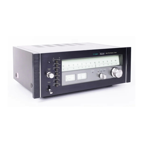
Sansui TU-505 Troubleshooting guide

OPERATING
INSTRUCTIONS
&
SERVICK
MANUAL
FM/AM
STEREO
TUNER
SANSUI
TU-505
Sansut
SANSUI
ELECTRIC
Co.,
LTD.

OPERATION
a
aE
ST
a
SS
SSS
ay
TSE
Congratulations
on
joining
the
thousands
of
proud,
satisfied
owners
of
quality
stereo
components
from
Sansui.
-
As
the
world’s
foremost
audio-only
specialist,
Sansui
has
spared
no
effort
in
making
the
TU-505
one
of
the
most
sensitive,
most
versatile
tuners
ever
marketed.
It
is
packed
with
state-of-the-art
circuitry
and
a
multitude
of
sophisti-
cated
features.
The
easy-to-tune
wide
dial
with
linear
FM
scale,
noise-
free
FM
tuning,
FM
antenna
switch
that
attenuates
exceedingly
strong
stations,
and
convenient
tape
recording
outputs
are
just
a
few
examples.
It
is
distinctively
styled
with
a
refined
satin-black
front
panel,
walnut
side
panels
and
a
highly
rational
layout
of
controls
and
switches.
This
manual
and
the
enclosed
reference
sheet
have
been
prepared
to
guide
you
in
operating
and
caring
for
your
TU-505
correctly.
Please
read
them
once
carefully,
then
retain
them
for
future
reference.
SETTING
UP
YOUR
TU-505
Before
you
insert
the
power
cord
into
a
wall
AC
outlet,
be
sure
to
make
the
following
preparations.
FM
Antenna:
Connect
the
T-shaped
feeder
cable
antenna
supplied
to
the
tuner’s
FM
300Q,
terminals.
Adjust
the
tuner
for
FM
reception
and
stretch
the
antenna
to
a
full
‘T’
shape,
then
adjust
its
height
and
direction
until
you
obtain
the
best
reception.
_
AM
Bar
Antenna:
In
areas
where
broadcast
signals
are
sufficiently
strong,
clear
AM
reception
is
obtained
simply
by
pulling
the
built-in
AM
ferrite
bar
antenna
away
from
the
rear
panel.
Amplifier:
Connect
the
OUTPUT
terminals
of
the
tuner
with
the
TUNER
or
AUX
terminals
of
your
amplifier
(integrated
amplifier
or
preamplifier),
using
the
pair
of
pin
plug
cables
supplied.
Be
FM/AM
RECEPTION
1.
Turn
the
Selector
Control
to
FM
AUTO
or
AM,
whichever
you
may
wish
to
hear.
2.
Select
the
desired
FM
or
AM
station
by
turn-
ing
the
Tuning
Control.
The
station
is
correctly
tuned
in
when
the
Signal
Meter
pointer
has
swung
as
far
to
the
right
as
possible.
If
the
FM
station
received
is
broadcasting
in
stereo,
the
FM
Stereo
Indicator
will
illuminate.
HINTS
FOR
BETTER
RECEPTION
@To
receive
a
weak
FM
station
Turn
off
the
FM
Muting
Switch
and
then
tune
in
the
desired
station.
With
the
FM
muting
circuit
at
work,
the
interstation
noise
commonly
heard
during
careful
not
to
confuse
the
left
and
right
channels.
Tape
Deck:
If
you
connect
the
tuner
to
a
tape
deck,
you
can
record
directly
from
the
tuner.
Con-
nect
the
TAPE
REC
terminals
of
the
tuner
with
the
recording
input
terminals
of
your
tape
deck,
also
using
pin
plug
cables.
FM
tuning
is
shut
out
but
weak
stations
may
also
be
cancelled.
@To
suppress
loud
noise
during
AM
or
FM
reception
Set
the
Noise
Suppressor
Switch
to
IN.
If
no
loud
noise
is
heard,
be
sure
to
keep
it
at
OUT.
@
When
receiving
an
excessively
strong
station
If
the
FM
signal
is
too
strong,
the
received
sound
may
be
distorted
and
crack.
In
this
case,
change
the
FM
Local/Distant
Antenna
Switch
over
to
LOC.
Otherwise,
be
sure
to
leave
it
at
DIST.

SIMPLE
MAINTENANCE
HINTS
OUTDOOR
FM/AM
ANTENNAS
In
areas
remote
from
broadcast
stations
or
blocked
by
such
obstacles
as
mountains
and
large
buildings,
the
‘T’
shaped
FM
antenna
supplied
and
the
built-
in
AM
ferrite
bar
antenna
may
sometimes
fail
to
give
you
clear
receptions.
To
improve
the
quality
of
reception
in
such
areas,
try
the
following
meas-
ures.
Outdoor
FM
Antenna:
Install
a
commercially
available
FM
outdoor
antenna
with
at
least
five
to
seven
elements.
While
such
antenna
may
be
con-
nected
to
the
tuner
either
with
300-ohm
balanced
feeder
cable
or
75-ohm
unbalanced
coaxial
cable,
the
use
of
the
latter
is
recommended
because
of
its
better
signal
transmission
capability,
if
your
budget
allows
at
all.
An
impedance
matching
transformer
may
be
sometimes
required
to
connect
such
antenna,
and
this
should
be
found
out
at
the
time
of
purchas-
ing
it.
After
connecting
the
antenna,
adjust
its
height
and
direction
so as
to
obtain
the
best
recep-
tion
while
actually
listening
to
your
favorite
FM
station.
Outdoor
AM
Antenna:
Connect
the
PVC
cord
supplied
to
the
AM-A
antenna
terminal
on
the
tuner’s
rear
panel,
then
extend
it
outside
a
window
or
on
the
roof,
SHOULD
THE
POWER
FUSE
BLOW
If
the
dial
indicator
should
fail
to
glow
and
your
TU-505
remains
dead
when
you
turn
on
the
Power
Switch,
it
is
possible
that
its
power
fuse
has
blown.
If
this
happens,
disconnect
the
power
cord
from
the
AC
outlet
and
examine
the
power
fuse
on
the
unit’s
rear
panel.
If
you
find
it
blown,
replace
it
with
a
new
glass-tubed
fuse
of
the
rated
capacity
(0.5-
ampere
for
100/117
volts,
0.3-ampere
for
220/240
Sy)
ce
7:
volts).
Never
use
a
fuse
of
a
different
capacity
or
a
piece
of
wire,
even
as
a
stopgap
measure,
or
serious
danger
could
result.
LTD.
en?
ED
Reploce
with
same
a
type
=
O.5A-250¥
fuse
at
100/117¥
O3A-2509
fuse
at
220/240¥
REAR-PANEL
AC
OUTLET
|
The
AC
outlet
marked
‘UNSWITCHED”
on
the
rear
panel
can
be
used
like
any
other
outlet
for
AC
house
current.
The
voltage
delivered
at
this
AC
outlet
is
the
same
as
the
power
supply
voltage
used.
This
AC
outlet
has
a
power
capacity
of
150W.
Before
you
connect
any
appliance
to
it,
be
sure
that
it
is
adjusted
for
use
at
the
same
power
supply
volt-
age,
and
that
its
power
consumption
is
not
greater
than
150W.
VOLTAGE
ADJUSTMENT
Your
TU-505
is
adjusted
to
operate
at
the
correct
power
supply
voltage
of
your
area
prior
to
ship-
ment
from
our
factory.
Should
you
move
after
purchasing
the
tuner
or
send
it
to
someone
as
a
gift,
it
may
be
necessary
to
adjust
the
Voltage
Selector.
To
adjust
it:
1.
Remove
the
two
screws
securing
the
name
plate
on
the
unit’s
rear
panel,
then
remove
the
name
plate.
2.
Unplug
the
Voltage
Selector
once,
and
reset
it
so
that
the
arrow
mark
on
it
faces
the
correct
volt-
age
indication.
3.
Change
the
power
fuse
as
well
whenever
the
power
supply
voltage
has
changed.
For
100/117
volt
operation,
use
a
0.5-ampere
glass-tubed
fuse.
For
220/240
volt
operation,
use
a
0.3-ampere
one.
About
Servicing
Should
anything
ever
go
wrong
with
your
TU-
505,
or
if
you
have
any
question
about
it,
please
contact
the
Sansui
dealer
from
whom
you
purchased
it
or
your
nearest
Authorized
Sansui
Service
Station.

DIAL
MECHANISM
SPECIFICATIONS
HOW
TO
STRING
DIAL
MECHANISM
After
the
dial
string
is
properly
installed
around
the
dial
pointer
and
Tuning
Control,
follow
the
procedure
given
below
to
hook
it
around
the
outer
groove
of
the
double-groove
pulley
attached
to
the
variable
capacitor.
Diagram
shows
the
completed
stringing.
1.
String
the
outer
groove
from
inside
to
outside.
2.
With
the
string
so
wound
around
the
pulley,
fix
its
end
to
the
screw.
3.
Turn
the
Tuning
control
clockwise
until
it
begins
to
idle.
4.
Using
a
finger,
shift
the
string
leading
to
the
screw
toward
inside
of
the
same
outer
groove.
5.
Turn
the
Tuning
Control
to
confirm
that
the
completed
stringing
is
as
shown
in
the
diagram.
SPECIFICATIONS
FM
SECTION
TUNING
RANGE:
88
to
108MHz
SENSITIVITY
(IHF):
2.5uV
TOTAL
HARMONIC
DISTORTION
MONO
less
than
0.6%
STEREO
less
than
0.8%
SIGNAL
TO
NOISE
RATIO:
better
than
65dB
SELECTIVITY:
better
than
50dB
CAPTURE
RATIO
(IHF):
less
than
2.5dB
IMAGE
FREQUENCY
REJECTION:
better
than
50dB
at
98MHz
IF
REJECTION:
better
than
60dB
SPURIOUS
RESPONSE
REJECTION:
better
than
60dB
SPURIOUS
RADIATION:
less
than
34dB
STEREO
SEPARATION:
better
than
35dB
at
400Hz
FREQUENCY
RESPONSE:
30
to
15,000Hz
+1dB,
—2.5dB
ANTENNA
INPUT
IMPEDANCE:
300
ohms
balanced,
75
ohms
unbalanced
ANTENNA
ATT.:
20dB
AM
SECTION
TUNING
RANGE:
SENSITIVITY
(Bar
Antenna):
50dB/m
535
to
1,605KHz
SELECTIVITY:
better
than
25dB
IMAGE
FREQUENCY
REJECTION:
better
than
80dB/m
at
1,000KHz
IF
REJECTION:
better
than
80dB/m
TAPE
REC
OUTPUT:
0.4V
OUTPUT:
1.0V
SEMICONDUCTORS:
Transistors
27;
FET
1;
Diodes
19;
IC
1
POWER
REQUIREMENTS:
POWER
VOLTAGE
100, 117,
220,
240V
50/60Hz
POWER
CONSUMPTION
Max.
16VA,
Rated
14
Watts
115mm
(4%”)
H
407mm
(16167)
W
278rnm
(11”)
D
WEIGHT:
5.5kg
(12.1
Ibs.)
DIMENSIONS:

[rer
nrc
merits
ee
reasoners
teenie
SCHEMATIC
DIAGRAM
Fitzy
3Sk39(Q)
Tey:
ae
Se
tg
gee
Pa
ee
ee
TA-7O6IAP
t
'
‘
28C1047(8)
Tos
2SC710(D)
Seep
23504
Tiga
Rng
$8
@SC93BO(C)
TRioe
2SCS37(E)
sr
Rea
190
Lae
Rego
2K
Thon
Teor
TPece
2SC7IKG)
2SCT7IIIF)
2SA678(6,7)
(0)
D)
Saar
2a
6.34
Toor
SIGNAL
MEIER
‘ee
BLUE
*
TReog9,
410
28C634A(6)
Sis
x
Our
PUT
4g,
2
=
a
Lea.
D
50H
1452-1
|imo2Scio6i(B
.
C)
Sx,
REC
OUT
3
Dar
ayy
15th)
aa
CSA
Moaet
Ory
Fern
IB
EOS
GF
eset.
Peoster@”
i]
—“—sCSd
ge
PE
tees
Ss:
pay.
thet
SWITCHES
S)oureur
Su
IE
S:
POLES
S¥¥
RChe
sod
1)
8?
—e
m3
Fog
|
c
“Fat
auTO
+
2Sc87IR(F)
1o\p
2
FAL
MONO
B01
034
250.
—
$|
207
Dov
0.38
2s
;
21
i
aml
“a
LA
Modet
onty.
ms
NOTICE
CAPACITOR:
a
2
CERAMIC
©
cre
CAyAceres,
WO
TBE
A0IS
MENT
©
wear
2u0¥
2
oy
ST
YROL
‘
ney.
5
i
Pa
Recta
cif
Sis
FS
ANTENNA
ATTENUATOR
@
TANTALUM
ELECTROLYTIC
peut
ee
74
f
eet]
2s
:
]
1.
ost
BP
B1-POLAR
ELECTROLYTIC
notte
5
mmr
at
C
ie
mors
2.
100
RESISTOR
SAL
RESISTORS
(&WATTS
UNLESS
OTHERWISE
NOTED,
V:0£
VOLTAGE
AT
NO
INPUT
SIGNAL.
rr

PRINTED
CIRCUIT
BOARDS
AND
PARTS
LIST
W:
Parts
No.
X:PartsName
Y:Stock
No.
Z:
Position
of
Parts
(
Ee
TUNER
BLOCK
<F-1453-1>
Stock
No.
7520550
i
WwW
xX
Y
z
3
Ww
x
Y
Zz
Rio1
120kQ,
0106124}
1D
R209
1kO
0106102
|
1C
i
Rio2
220kx0,
0106224
|
1D
Rai0
1kQ,
0106102}
1C
R103
120k0,
0107124}
1D
Rat
3302
0107331
|
1C
R104
1000,
0107101
|
1D
R212
2200,
0107221
|
1B,C
R105
2200,
0107221}
1D
R213
560
0106560
|
1B
Rig
5.6kO,
0106562
|
1D
Rai4
§.6kO,
0106562
|
1B
Rio7
12kO,
0107123
|
1D
Rais
2200,
0106221
|
1B
Rios
3.9kO,
0107392
|
1D
R216
1kQ,
0106102
|
1A,
B
Riio
2200,
0107221
|
1D
R217
1kO
0106102}
1A,
B
R111
1200,
0106121
|
1D
R218
1000,
0107101
|
1B
Rir2
6.8k0,
0106682
|
1D
R219
6.8k0,
0106682
|
1A,
B
Rii3
47kQ
0106473
11D
R220
6.8kO
0106682
1
1A,
8
Riu4
1.5kO
0106152}
1D
R221
1000
\
5%
YW
CR
0107101
|}
1B,C
Riis
390)
+
5%
Kw
cr}
0106390
|
1D
R222
15k,
{
~
:
"|
0106153
|
2c
Rité
2.2kQ,
0107222
|
1D
R223
4.7kQ
0106472
|
2C
Ruiz
Tka
0106102
1C
R224
TkQ
0107102
|
2B
Rig
27k
0106272
|
1D
R225
1000,
0107101
|
2B
Rig
56k0,
0106563
|
1C
R226
1$kO
0106153
|
2B
R120
33k0,
0106333
|
1C
R227
4.7kO,
0106472
|
2B
R201
2200,
0106221;
1C
R228
1kQO
0106102
|
2B
R202
3.3k0,
0106332
|
1C
R229
2200
0106221
|
2B
R203
1.5kQ,
0107152
|
1¢
-
R230
2200,
0106221
|
2A,
B
R204
1kQ
0106102
|
1c
R231
1kO
0107102
|
2B
(
R205
3300,
0106331
|}
1c
R232
100
0107100
|
1B
R206
3.3k0,
0106332
|
1C
R301
10kQ
;
0107103
|
2c
R207
1.5kQ,
0106152
|
1C
;
R302
220,
0107220
|
1,2C
R208
1009,
0106101;
1C
R303
1kO.
0107102}
1,2C
=
-Abbreviations——_
Carbon
Resistor
Solid:
Resistor
_
Metal
Oxide
Film
esistor.
Ceramic
Capacitor
Electrolytic
Capa
:
-
Aluminlum
Solid
i
Bi-
Polar
Electrolytic
Metallized
Polyester
Capacito
-
Styrol
Capacitor
:
~
Mica
a
Capacitor”
ee
f
BE
|
ey
Hl
Lo

R304
R305
R306
R307
R308
R309
R310
R311
R312
R313
R314
Rais
R316
R317
R318
R319
R320
R321
R322
R324
R325
R326
R327
R328
Raol
Rao2
12kQO,
82kQ,
10k
680,
8200,
1200
8.2kO,
15kOQ,
4.7kO
5600,
1200,
10kQ,
2200,
10kO,
4.7kO,
39kO,
§.6kO,
22kQ,
5.6kO,
1kQ,
5600,
5600,
1200
47kQ
8.2kQ,
1kQ,
100k,
+
5%
MW
CR.
Y
0107123
0106823
0106103
0106680
0106821
0107121
0107822
0106153
0106472
0106561
0107121
0107103
0106221
0106103
0106472
0107393
0106562
0106223
0106562
0106102
0106561
0107561
0107121
0106473
0106822
0107102
0107104
2C
2c
1,2C
1B,C
1B
2C
2B
2B
1B
1B
2B
2B
2B
1B
1B
1A,
B
1,2A
2C
2C
2C
2C
2C
2B
1,2B
1,BC
1B
1,2A
R403
R404
R405
R406
R407
R408
R409
R4i0
Rai
Rai2
R413
R414
R415
R416
Rai7
R418
R419
R420
R421
R422
R423
R424
R425
R426
R427
R428
R429
220k0,
TkQ
1000
4700,
3.3k0,
1kO,
100kQ,
100k
100kQ,
100k
8.2kO,
8.2k0,
8.2k0,
8.2k0,
56kO,
56kQO,
82kO,
82k,
2700
22k0,
47kO,
10kQ
47kQ,
IMQ
15kQ
560,
47kQ
+
5%
MW
CR
+10%
1W
MFR,
+
5%
Mw
CR
Y
0107224
0106102
0106101
0106471
0106332
0107102
0106104
0106104
0106104
0106104
0106822
0106822
0106822
0106822
0106563
0106563
0106823
0106823
0171271
0106223
0106473
0106103
0106473
0106105
0106153
0106560
0106473
1,2A
1A
2A
2A
TA
2A
2A
1A
2A
2A
2A
1A
2A
1A
2A
1A
2A
1A
2A
2A
2A
2A
28
2A
2A
2A,
8B
2A,
8B

PRINTED
CIRCUIT
BOARDS
AND
PARTS
LIST
TUNER
BLOCK
<F-1453-1>
Cont'd)
Stock
No.
7520550
Ww
R431
R432
R433
R434
VR201
VR301
VRa01
VR402
Cio1
C102
C103
C104
C105
C106
Ci07
C108
Cio9
C110
Ci
C112
C13
C4
Cis
C6
Cuz
Cis
Cig
C120
C121
C201
C202
C203
C204
C205
C206
C208
C209
C210
C211
C212
C213
C214
C215
C216
C217
C218
C219
C220
C221
C222
C223
C224
C225
C226
C227
C301
4.7kO,
15kQ,
220k,
68kQ,
22kQ,
(B)
22kQ,
(B)
22kQ,
(B)
100kQ,
(B)
12pF
0.001
uF
0.022
uF
0.022
uF
0.022
uF
18pF
8.2pF
18pF
220pF
at
|
ee
0.022
uF
2.7
pF
18pF
10pF
10pF
10pF
0.022
uF
0.022
uF
0.022
uF
0.022
uF
0.022
uF
0.022
uF
0.022
uF
0.022
uF
0.022
uF
47
pF
0.022
uF
0.022
uF
0.022
uF
0.047
uF
0.022
uF
10
uF
220pF
220pF
220pF
0.022
uF
0.022
uF
0.022
uF
0.022
uF
0.022
uF
0.022
uF
0.047
uF
0.33
uF
0.022
uF
0.022
uF
0.047
uF
0.022
uF
!
|
|
|
)
|
Xx
+
5%
YW
CR
Signal
Meter
Adj.
(FM)
Signal
Meter
Adj.
(AM)
FM
Stereo
Indicator
Adj.
(AM)
FM
Muting
Adj.
+
5%
50V
CC.
+80
25V
CC.
50V
50V
+
5%
£0.5pF
+
5%
+10%
50%
£0.25pF
50V
+
5%
50V
cc.
cc.
cc.
cc.
cc.
ce.
cc.
50V
50V
25V
+0.25pF
50V
CC.
18%
=©28V
CC.
+10%
50V
CC.
123%
=
=-25V
CC.
25V
EC.
+10%
50V
CC.
+80%
=
25V
CC.
25V
TC.
Teo:
28
CC,
+80
9
0%
=
25V_
CC.
Y
0106472
0106153
0106224
0106683
1035150
1035150
1035150
1035190
0669347
0656102
0656223
0656223
0656223
0669353
0669209
0669347
0669353
0660221
0656223
0656223
0669203
0669378
0669370
0669370
0669320
0656223
0656223
0656223
0656223
0656223
0656223
0656223
0656223
0656223
0660470
0656223
0656223
0656223
0656473
0656223
0513100
0660221
0660221
0660221
0656223
0656223
0656223
0656223
0656223
0656223
0656473
0573338
0656223
0656223
0656473
0656223
z
1A
2B
1A
1,2A
2A,
8B
NON
N
on>w
oO
v00
900
00000
ANNANANVGIVIAGVGANTTYS
1,2C
1B
1B
1B
1B
1B,C
1A
1A
1A
18
2B
2B,C
2B
2B
2B
2B
2B
2B
2A
1B
2C
W:
Parts
No.
Ww
C302
C303
C304
C305
C306
C307
C308
C309
C310
C311
C312
C313
C314
C315
C316
C318
C319
C320
C321
C322
C323
C324
C325
C326
C327
C328
C330
C401
C402
C403
C404
C405
C406
C407
C408
C409
C410
C413
C414
Cats
C416
C417
C418
C419
C421
C431
C432
VCi01
~103}
301,
302
TCi03
TRioi
TRio2
TRi03
TRi04
TR201
TR202
X:
Parts
Name
Y:
Stock
No.
xX
+10%
+80
+10%
33pF
0.047
uF
0.01
uF
0.047
uF
ae
0.047
uF
3.3
HF
0.047
WF
aan
3.3
uF
0.0047
uF
0.047
pF
0.047
pF
0.01
uF
0.068
F
0.047
uF
15pF
0.01
uF
360pF
22pF
0.047
LF
47
pF
0.047ur
+896
0.002uF
+
5%
o.01ur
+899
33
uF
15
pF
3.3
HF
$800pF
6800pF
1000pF
100pF
270pF
104F
10
uF
|
|
|
|
50V
25V
50V
58%
+80
9,
+809
25V
25V
50V
+800
1%
«©
26V
25V
+80%
-25V
+10%
0%
+10%
+10%
+
5%
+10%
+80
9
50V
25V
50V
50V
50V
50V
_
(25
6.3V
25V
50V
25V
6.3V
50V
50V
+10%
50V
50V
25V
0.022uF)
—207°
aoy
1200pF
1200pF
1500pF
1500pF
0.1
uF
0.1
uF
1.5
pF
3.3
uF
820pF
820pF
50V
%
%
50V
25V
50V
es
+10
+
5%
50V
|
Variable
Capacitor
Ceramic
Trimmer
2SC1047
(B)
2SC930
(E)
28930
(C)
25C537
(E)
}
2SC1047
(B)
cc.
cc.
MC.
cc.
cc.
EC.
cc.
BPEC.
cc.
Mc.
CC.
Cc.
MC.
sc.
CC.
cc.
EC.
CC.
MC.
CC.
EC.
EC.
sc.
MiC.
EC.
cc.
MC.
TC.
EC,
$c.
Z:
Position
of
Parts
(
Y
Zz
0660330
0656473
0601107
0656473
0656473
0656473
0515339
0657473
0657473
0533339
0657472
0657473
0657473
0657103
0601687
0656473
0660150
0601107
0620361
0660220
0656473
0510470
0656473
0600206
0656103
0510330
0660150
0515339
0620682
0620682
0620102
0620101
0640271
0513100
0513100
0656223
0656223
0620122
0620122
0620152
0620152
0601108
0601108
0573159
0515339
0620821
0620821
1,2C
2C
2C
1c
1c
|
2B,C
2C
1B
2B
1B
18
28
2B
1B
2C
2C
2C
2C
2c
2B
28
2C
2B
2B
1A
1A
1A
1A
1A
1A
1A
1A
2B
2A
2A
1A
2A
1A
2A
1A
1A
2A
1220150
1230090
0305801
0305792
0305790
0305440
0305801
0305801
2C,D
2c
1D
1D
1c
1c
1c
1c

Ww
TR203
TR204
TR301
TR302
TR303
TR304
TRa401
TR4o2
TR403
TR404
TR405
TR406
TR407
TR408
TR409
TR410
D201
D202
D203
D204
D205
D301
D302
D303
D304
D401
D402
D403
D404
D405
0406
D407
D408
FETi0o1
1C201
Ti01
T102
T201
T202
T203
T204
T301
T302
T303
T304
T401
T402
L101
Lio2
L103
Li04
L201
L202
L301
L401
L402
L403
2SC1047(B)
28C710
(D)
2$C711
(G)
2SC711
(F)
28C711
(G)
25A697
(D)
28C711
(G)
28C711
(F)
2SA678
(6,
7)
2SC634A
(6)
[SaaS
1N60P
1N34A
DS-430
|
1$-1588
DS-430
10D-1
3SK39
(Q)
TA7061
AP
FM
IF
Coil
FM
Discriminator
Coil
YFL-455E2
or
CFW-455B
AM
IF
Coil
AM
OSC
Coil
FM
MPX
Coil
FM
Antenna
Coil
FM
RF
Coil
Choke
Coil
FM
OSC
Coil
3.34H
Micro
Inductor
3.5uH
Peaking
Coil
MPX
Coil
4.7mH
Ferri
inductor
MPX
Coil
F-1453
Printed
Cicuit
Board
Y
0305801
0305943
0305943
0305943
0305943
0305943
0305733
0305732
0305732
0305733
0300311
0305733
0305732
0300291,
2
0305891
0305891
0311060
0311060
0310400
0310400
0340090
0310400
0310400
0310400
0310400
0310400
0310400
0311180
0311180
0311180
0311180
0340090
0310340
0370080
0360060
4235890
4235900
4235750
4235760
4235770
4235780
0910180,
2
4230510
4230500
4220280
4240630
4240620
4200570
4210200
4290110
4220400
4900100
4290011
4290011
4240640
4900030
4240610
4520340
2c
2B
1,2C
1,2C
1,2B
2C
1A
2A
2A
2A
2A
2B
2B
2A
2A
1A
1B
1B
2B
2B
2C
1,2C
1,2B
1,2B
2A
2A
1A
TA
1,2A
2A
2A
1D
1B
1D
1c
1B
1B
28
2B
1,2C
1,28
1,2B
2C
1,2A
1D
1D
1D
1D
1c
1,2B
TA
TA
TA
MPX
DIFFERENTIAL
AMP
BLOCK
<F-1245-1A>
Stock
No.
7591270
w
|
x Y
|
Z
R501
2.2kOQ
0107222
|
A
R502
2.2k0,
0107222!
A
R503
150kQ
0107154]
A
Rs04
150k0,
0107154]
A
Rs05
22k0,
0107223
|
A
R506
22k,
0107223
|
A
Rs07
10kQ
0107103
|
A,
B
R508
10kQ
0107103
|
A,
B
Rs09
1kO
0107102]
A
R510
1kQ5+4
5%
Y%w
cr.
|
0107102]
A
R511
100kQ,
0107104
|
A,
B
Rs12
100kQ,
0107104
|
A,
B
R513
47kQ,
0107473
|
B
Rs14
47kQ,
0107473
|
B
R515
4.7kQO
0107472
|
B
R516
4.7kO
0107472
|
B
R517
100kQ,
0107104
|
B
Rsi8
100kQ,
0107104
|
B
Rsi9
2200,
0107221
|
A
VRs501
10kQ(B)
FM
Stereo
Separation
1035370
|
A
Adj.

PRINTED
CIRCUIT
BOARDS
AND
PARTS
LIST
W:
Parts
No.
X:
Parts
Name
Y:
Stock
No.
Z:
Position
of
Parts
H
|
<F-1245-1A)
cont’a)
Stock
No.
7591270
Stock
No.
7500700
Ww
x Y
Z
Ww
x
Y
Zz
‘C501
et
0515109
|
A
Roo1
1.5kQ,
0101152
|
A,B
:
+10%
3}
.
‘
C502
1
uF
Sew
HES.
0515109
|
A
Roo2
ao
10%
YW
CR
0101152
|
A,
B
C503
10/F
0513100
|
A
Roos
150,
0111150}
A,
B
25V
EC,
C504
10
uF
0513100
|
A
Roo4
220,
0111220
|
A
C505
470pF
0620471
|
A,
B
Roos
4700.)
410%
MB
sr.
0111471
|
A,
B
C506
A70pF
0620471
|
A,
B
Roo7
6.82,
0111689
|
A
C507
1200pF
0620122
|
B
Roos
109,
0111100
|
B
+
g
C508
1200pF
{
~~
5%
S50V
SC.
0620122
|
B
Roos
332
+5%
Www
cr.
0107330
|
B
C509
1000pF
0620102
|
B
Csi0
1000pF
0620102
|
B
Coo1
220
p!F
0515221}
A
Csi)
Be
2sV
EC
0613100
|
B
Co02
100
uF
SOV
EC.
0515101
|
B
C512
10uF)
,
0613100
|
B
Co03
100uF
0515101
|
B
Cs13
0.0033uF
+10%
S50V
MC.
0601336
|
A
Coo4
4
Daye
tee
0513331
|
B
Cs14
o.047ur
8%
28v
CC.
|
0656473
Coos
100
uF
;
0513101
|
B
TRs01
0305475
|
A
Coo7
470
pF
10V
EC.
0511471!
A,
B
TRé02
0305475
|
A
Coos
o.o1ur
+'%%
soov
cc.
0655103
|
A
TRso3
|
7
25C871R
(F)
0305475
|
B
Coos
10uF
25V
EC.
0513100
|
B
TRs04
0305475
|
B
Ls01
Pe
4240570
|
B
TRoo1
25C1061
(B,
C)
0305771,2}
A,
B
L502
4240570
|
B
e
1001
0310340
|
A
E
:
i
ircvi
9127
F-1245-1
Printed
Circuit
Board
2591270
Dooe
10D-1
0310340
|
A
Doo3
0310340
|
A
ZDoo1
RD-24A
(N)
0315420
|
A,
B
Foi
3A
0432870
|
A
Fo2
0.5A
?)
Wired
in
Fuse
0432810
|
A
Fo3
0.5A
0432810}
A
F-1452
Printed
Circuit
Board
2500590
List
of
Accessories
1.
FM
ANTENNA
1
2.
AM
ANTENNA
1
3.
CONNECTION
CABLE
WITH
PIN
PLUGS...
2
A;
POLISHING
CLOTH
is
ccte
cd
enuvesecaveuudieans
1
5.
OPERATING
INSTRUCTIONS
AND
SERVICE,
MANUAL.
cine
cuus
idee
dara
seveuadesaete
1
6.
OPERATING
INSTRUCTIONS
SHEET
......
1
¥

OTHER
PARTS
AND
THEIR
POSITION
ON
CHASSIS
OTH
ER
PARTS
*Design
and
specifications
subject
to
change
without
notice
for
improvements.
Ww
x
Y
Ww
x
Y.
Row
1k,
0107102
L302
AM
Bar
Antenna
4220550
Ros)
1.5kO,
0107152
L303
1002H
Micro
Inductor
4900110
Ros2
1.5kO,
0107152
Ros3
3.3k0,
0107332
Mooi
Signal
Meter
4300560
Ros4
:
+
5%
3
i
0107332
Ross
:
ir
=
5%
AW
CR
nee
PUoo1
Voltage
Selector
Plug
2410090
Rosé
3.90,
0107392
Voltage
Selector
Socket
2410080
Ros7
3.9kO,
0107392
COo01
AC
Outlet
2450040
Ross
3.9kQ
0107392
Foo1
0.5A
Power
Fuse
(100/117V)
0431212
Con
0.001uF
+10%
50V
MC.
0601106
0.3A
Power
Fuse
(220/240V)
0431202
Co12
0.033uF
420%
250V
MPC.
0605337
Power
Fuse
Holder
2300060
Co13
0.0047uF
+809
ov
CC.
0659802
BE
Sgt:
BOY.“
.
PLoor~oos
|
7V
0.33A
Dial
Scale
Lamp
0420040
Cou
|
ae
eee:
sees
Ie
0601686
Liang
Holey
225)
esiogse
Cois
|
0.0068
uF
0601686
PLoos
|
6.3V
75mA
Dial
Pointer
Lamp
0400200
$1
Power
Switch
1190020,
1
PLooz
6V
0.03A
FM
Stereo
Indicator
0400110
S2
!
Selector
Control
F-1-4-3
1101441
Power
Supply
Cord
3800020
$3
FM
Muting
Switch
1170060
S4
|
Noise
Suppressor
Switch
1170060
Lug
Board
1L1
2110010
Ss
FM
Antenna
Attenuater
Switch
1110040
Lug
Board
2L1
2110120
Lug
Board
IL1P
2110060
Too!
Power
Transformer
4001200
F=1452
Power
Supply
Unit
7500700
Loo1
100mH
Ferri
Inductor
4900190
F-1453
Tuner
Unit
7520550
Loo2
3.34H
Ferri
Inductor
4900100
F-1245-1A
MPX
Differential
Amp
Unit
7591270
RO55,056
RO52,054
f
‘
L302
R05
1,053
:
;
S5
PUOO1
R058
FOO1
RO57
COQo01
L303
C013
R014
C011,014,015
L001
Co12
PLOOS
Moo1
PLOO7
=)

Sansut
SANSUI
ELECTRIC
CO.,
LTD.
14-1,
2-chome,
Izumi,
Suginamiku,
Tokyo
168,
Japan.
TELEPHONE:
(03)
323-1111/TELEX:
232-2076
Stock
No.
9207140
Printed
in
Japan
(53710M3)
Table of contents
Other Sansui Tuner manuals

Sansui
Sansui TU 777 Troubleshooting guide

Sansui
Sansui TU-666 Troubleshooting guide

Sansui
Sansui DR201V User manual

Sansui
Sansui TU-7700 User manual

Sansui
Sansui TU-S77AMX User manual

Sansui
Sansui TU 777 Troubleshooting guide

Sansui
Sansui TU-9900 User manual

Sansui
Sansui T-80 User manual

Sansui
Sansui TU-717 User manual
Sansui
Sansui tu-x701 User manual