FOR YOUR SAFETY
“WHAT TO DO IF YOU SMELL GAS”
• Do not try to light any appliance.
• Do not touch any electrical switch; do not use any
phone in your building.
• Immediatelycallyourgassupplierfromaneighbor’s
phone. Follow the gas supplier’s instructions.
• If you cannot reach your gas supplier, call the fire
department.
Do not use this LP Gas control on a Natural Gas
water heater. Improper operation could occur, re-
sulting in personal injury and/or death due to Car-
bonMonoxidepoisoning,fire,orexplosion.Check
for proper gas type as listed on the rating plate
affixed to the water heater.
This gas control is equipped with LEFT-HAND threads in
the outlet for use on LP gas water heaters where the
connection between the gas control and the main burner
manifold are with LEFT-HAND threads.
FAILURE TO READ AND FOLLOW ALL INSTRUCTIONS BEFORE INSTALLING OR OPERATING THIS
CONTROL COULD CAUSE PROPERTY DAMAGE, PERSONAL INJURY AND/OR DEATH.
RETAIN INSTRUCTIONS FOR FUTURE REFERENCE.
NOTE
1. This control must be installed or serviced only by a
professional.
2. Do not use force when moving the gas control knob. If
you cannot turn the knob with hand pressure only, the
control must be replaced.
3. Do not use the control if the knob will not “pop up” after
being depressed while the knob is in the PILOT posi-
tion. The mechanism is damaged and the control must
be replaced. Shut off gas to the water heater.
4. For your safety, this control is supplied with tamper
resistant screws. Do not attempt to repair or adjust the
control.Ifyouexperienceproblems,replacethecontrol
immediately. Continuing to use a damaged control
could result in fire and/or explosion.
5. LP gas is heavier than air. Leaking gas will settle near
the ground and will tend to accumulate.
6. An odorant has been added to the gas to help you
detect it. Before lighting, search for the odor of gas by
sniffing at floor level around the water heater.
7. Insomesituations,thegasmayloseitsodor.Todetect
unodorized gas, you must have a gas detector which
canbepurchasedfromyourgascompany.Ifyoudonot
have a detector and have the slightest suspicion that
gas may be present, get out of the house and call the
gas company. DO NOT RELY TOTALLY ON YOUR
NOSE.
8. Ifanyproblemsorquestionsareencounteredaboutthe
safe use of LP gas, contact your local gas supplier.
Scald burns occur in under one second with 160°
water, which this thermostat will deliver if the
temperature dial is set at “VERY HOT”. Lower
settingsofthetemperaturedialwillreducetherisk
of scald and will reduce your fuel bill.
A
B
C
P
I
L
O
T
L
I
G
H
T
I
N
G
L
O
W
H
O
T
V
E
R
Y
RISK OF SCALDING
INCREASES WITH
HOTTER WATER
CAUTION:
Printed in U.S.A.
WHITE-RODGERS DIVISION
EMERSON ELECTRIC CO.
9797 REAVIS ROAD
ST. LOUIS, MISSOURI 63123-5398
PART NO. 37-6093A
9912
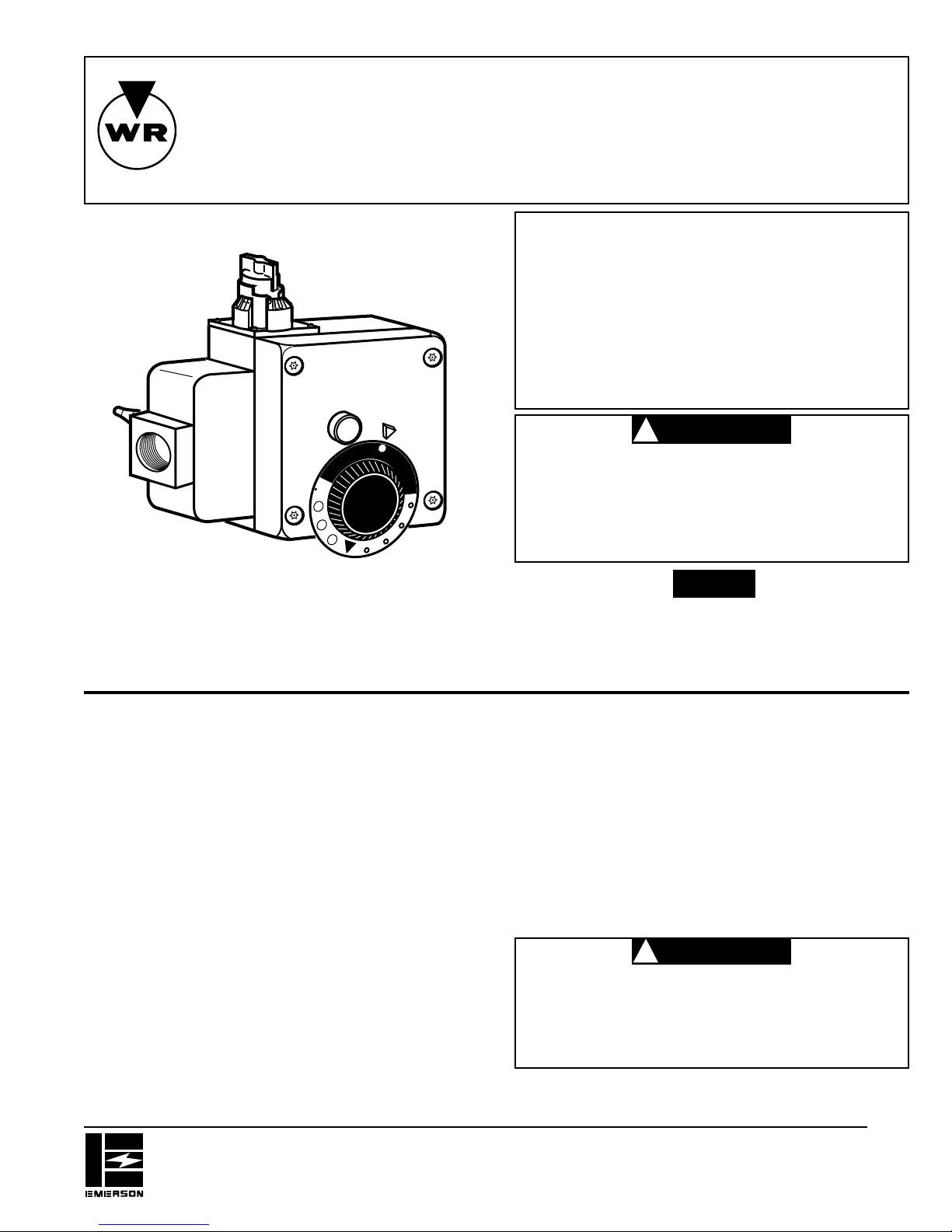
37C72U
Water Heater Thermostat Control
Installation Instructions
(Left-Hand Outlet Thread Model)
FOR LP GAS ONLY
WHITE-RODGERS
Fixed Adjustment Main and Pilot Regulators
The main and pilot gas regulators require no field
service. They automatically control and maintain the
outlet main and pilot burner gas pressure.


