WHITEHALL MANUFACTURING • P.O. BOX 3527 • City of Industry, CA 91744-0527 U.S.A
Phone (800) 782-7706 • (626) 968-6681 • Fax (626) 855-4862 • Web: www.whitehallmfg.com
a
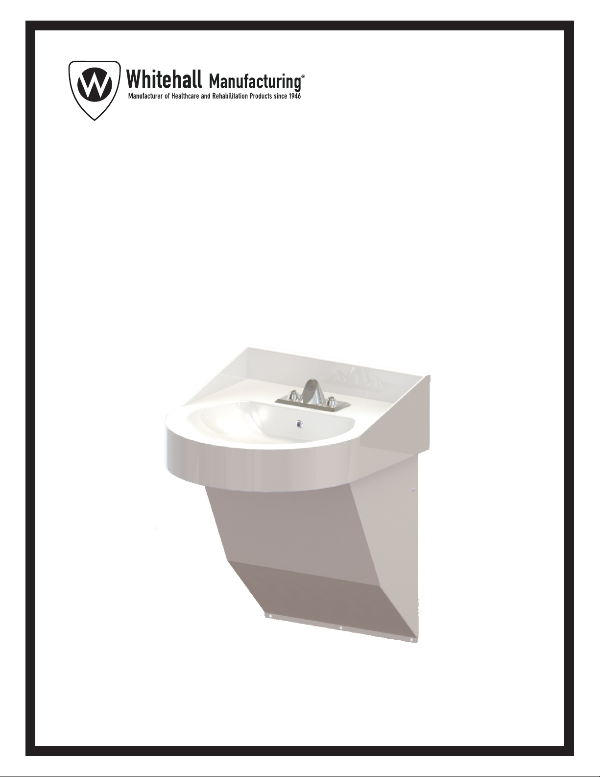
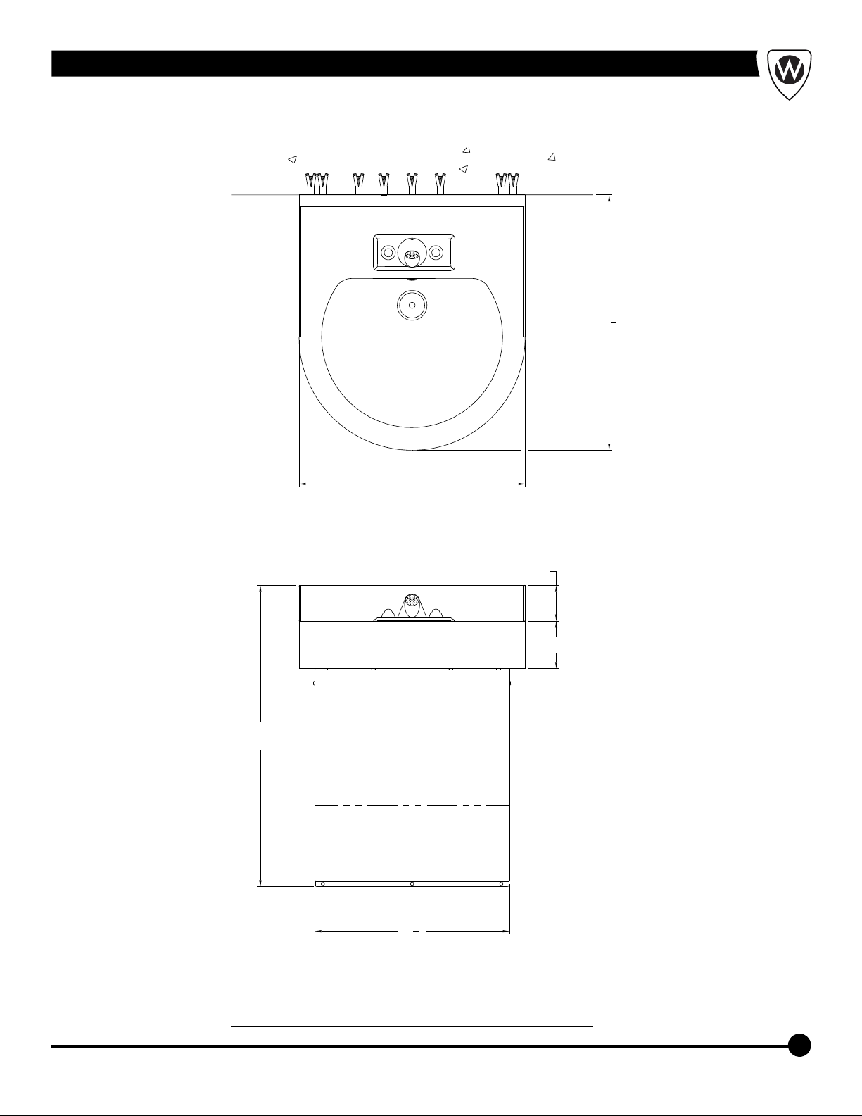
Instructions for Operation and Care of Best-Care WH3740
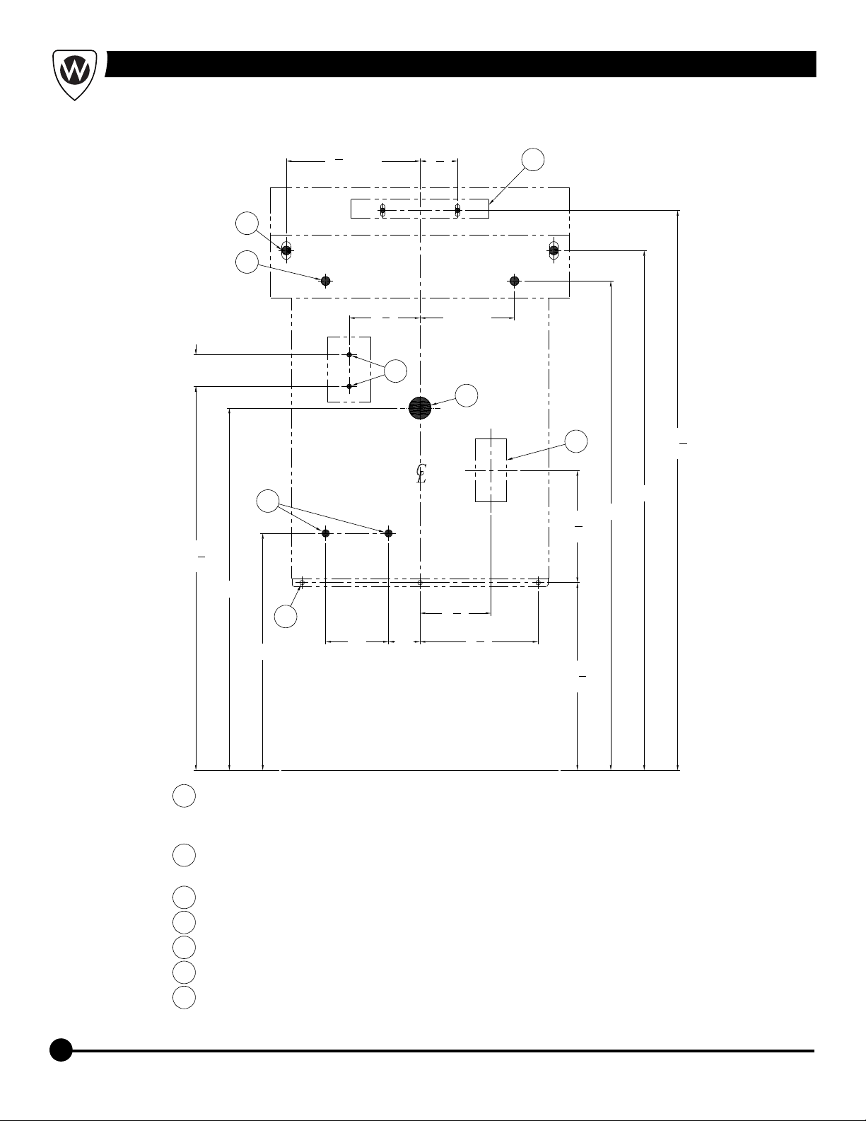
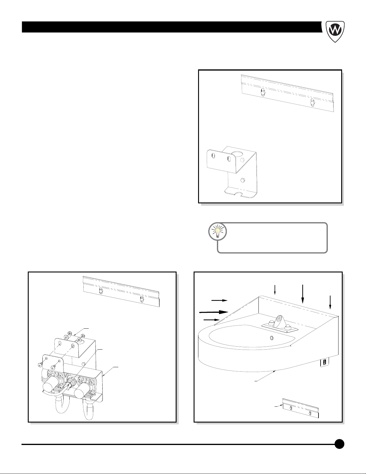
Prior to installation, supply lines must be flushed of all foreign material such as pipe
dope, chips, or solder. Debris or foreign material in water supply may damage valve.
NOTE: Receptacle(s) must be wired to a GFCI protected circuit. Fixture must be earth
grounded per N.E.C. (National Electrical Code).
Single Temp Valve Assembly: Recommended working water pressure is 30 psi (2.07
bars) minimum to 100 psi (6.89 bars) maximum. Maximum temperature is 130°F
(54.4°C). Maximum outlet temperature recommended is 105°F (40.6°C). Valve
assembly must be drained prior to being subjected to freezing temperatures.
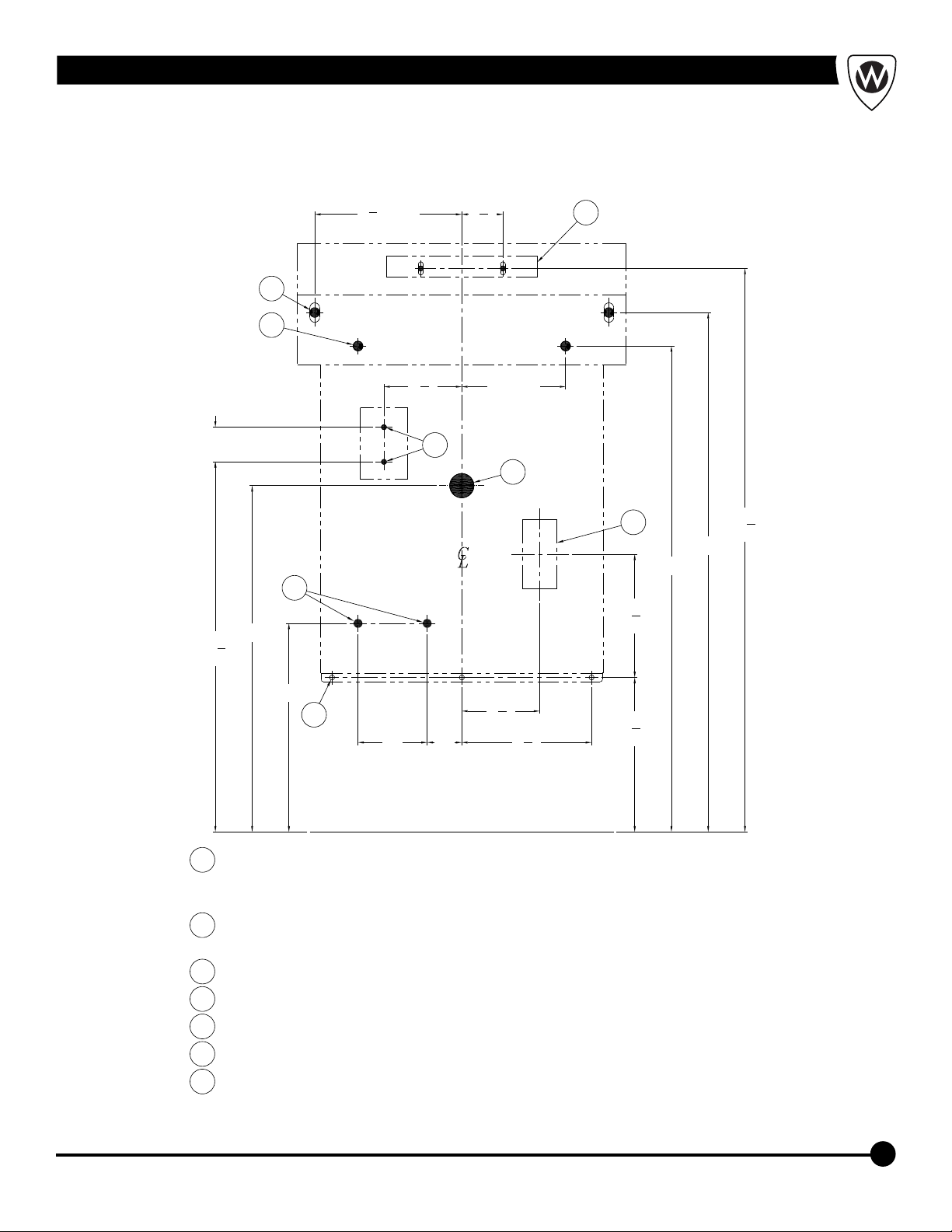
Industry standard wall backing, for wall hung fixtures, is required. Installer provided wall
anchors and wall anchoring hardware with a minimum Pull-Out Force of 1000 pounds
(lbs) per anchor for appropriate wall construction.
Important: Some options may slightly alter installation. To ensure proper installation
review the manual thoroughly and verify rough-ins before beginning any work. File this
manual with the owner or maintenance personnel upon completion of installation.
Teflon tape is recommended on all threaded waste and supply connections to reduce the
possibility of leaks.
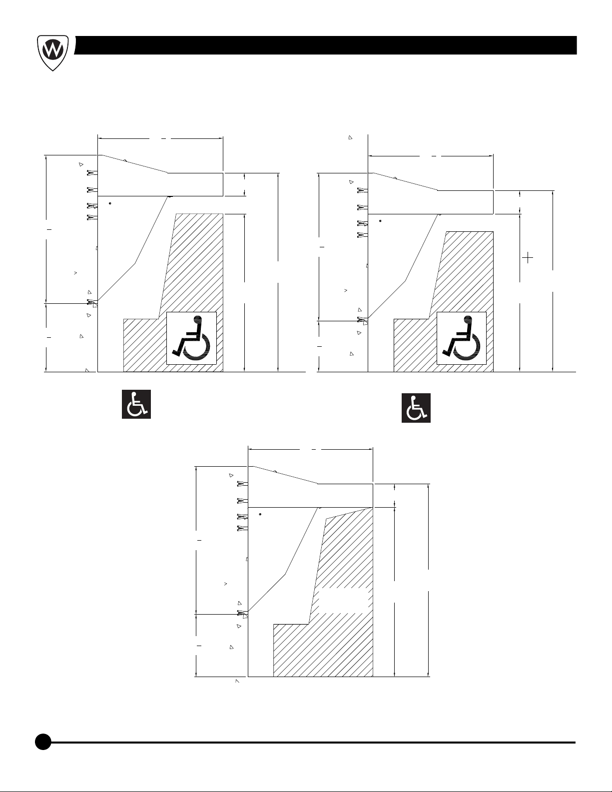
ANSI, UFAS or ADA compliance is subject to the interpretation and requirements of the
local code authority and is the responsibility of the installer for verification.
Provide 110-120VAC/60Hz/3A (MAX) electrical receptacle for factory supplied
120VAC/9VDC, 100mA plug-in transformer if required.
Upon receiving, verify count and inspect packaging for obvious signs of damage or
missing containers. If there are any issues upon receiving make note on bill of lading and
report to carrier and manufacturer promptly. Remove fixture assemblies from packaging
and ensure all parts are present before beginning installation. Do not discard packaging
until all parts have been accounted for. Refer to Acorn terms, conditions of sales and
warranty for more information.
T/P Mixing Valve Assembly: Recommended working water pressure is 30 psi (2.07 bars)
minimum to 100 psi (6.89 bars) maximum. Maximum hot water temperature is 180°F
(82°C). Temperature adjustment range is 85-115°F (29-46°C). Minimum hot water
supply temperature must be 5°F (3°C) above desired set temperature. Valve assembly
must be drained prior to being subjected to freezing temperatures. The valve assembly
has checks integral to the inlets however, angle stops are to be provided by the installer.