Whitehall WHD-BSN Instruction manual

WHITEHALL MANUFACTURING • P.O. BOX 3527 • City of Industry, CA 91744-0527 U.S.A
INSTALLATION, OPERATION & MAINTENANCE MANUAL WHD-BSN
6900-220-001 Revised: 10/17/2023 B
Model WHD-BSN
®
LIGATURE RESISTANT
TM
CORTERRA BASIN ADA
COMPLIANT
Important: Some options may slightly alter installation. To ensure proper installation review the manual thoroughly and
verify rough-ins before beginning any work. File this manual with the owner or maintenance personnel upon completion of
installation.
Industry standard wall backing, for wall hung fixtures, is required. Installer provided wall anchors and wall anchoring
hardware must be appropriate for wall construction.
ANSI, UFAS or ADA compliance is subject to the interpretation and requirements of the local code authority and is the
responsibility of the installer for verification.
Single Temp Valve Assembly: Recommended working water pressure is 30 psi (2.07 bars) minimum to 100 psi (6.89 bars)
maximum. Maximum temperature is 130°F (54.4°C). Maximum outlet temperature recommended is 105°F (40.6°C).
Valve assembly must be drained prior to being subjected to freezing temperatures. A checkstop is provided with this valve
assembly.
T/P Mixing Valve Assembly: Recommended working water pressure is 30 psi (2.07 bars) minimum to 100 psi (6.89 bars)
maximum. Maximum hot water temperature is 180°F (82°C). Temperature adjustment range is 85-115°F (29-46°C).
Minimum hot water supply temperature must be 5°F (3°C) above desired set temperature. Valve assembly must be
drained prior to being subjected to freezing temperatures. The valve assembly has checks integral to the inlets however,
angle stops are to be provided by the installer.
Prior to installation, supply lines must be flushed of all foreign material such as pipe dope, chips, or solder. Debris or
foreign material in water supply may damage valve.
Teflon tape is recommended on all threaded waste and supply connections to reduce the possibility of leaks.
Provide 110-120VAC/60Hz/3A (MAX) electrical receptacle for factory supplied 120VAC/9VDC, 100mA plug-in
transformer.
NOTE: Receptacle(s) must be wired to a GFCI protected circuit. Fixture must be earth grounded per N.E.C. (National
Electrical Code).
WHD-BSN-WH3375-SO
(Photo shows optional accessories)
Please refer to the Link or QR code provided.
For Cleaning & Care Guide:
https://www.whitehallmfg.com/uploads/fileLibrary/9900-008-W01.pdf
TECHNICAL ASSISTANCE TOLL FREE TELEPHONE NUMBER:
1.800.743.8259
Technical Assistance E-mail: [email protected]

WHITEHALL MANUFACTURING • P.O. BOX 3527 • City of Industry, CA 91744-0527 U.S.A
INSTALLATION, OPERATION & MAINTENANCE MANUAL WHD-BSN
2
WHD-BSN-WH3375-SO SHOWN
TECHNICAL DIMENSIONS
GENERAL NOTES:
ALL DIMENSIONS ARE IN INCHES [MM].
DIMENSIONS SHOWN ARE FOR RECOMMENDED ADULT HEIGHT. ADJUST VERTICAL
DIMENSIONS AS NECESSARY TO COMPLY WITH FEDERAL, STATE, & LOCAL CODES.
STOP VALVE NOT PROVIDED.
1.
*2.
3.
NOTE: FIXTURE WEIGHT IS APPROXIMATELY 90 LBS
WITH FAUCET (INDUSTRY STANDARD WALL BACKING,
FOR WALL HUNG FIXTURES, IS REQUIRED. INSTALLER
PROVIDED WALL ANCHORS AND WALL ANCHORING
HARDWARE MUST BE APPROPRIATE FOR WALL
CONSTRUCTION)
GENERAL NOTES:
1.
2.
3.
4.
5.
6.
BACK/SIDE SPLASH
LIGATURE RESISTANT DRAIN
P-TRAP ENCLOSURE
1-1/2” OD P-TRAP
TAMPER RESISTANT SCREWS
OPTIONAL WH3375-SO SHOWN
7. WALL ANCHORING HARDWARE (BY OTHERS)
27"
Min.
24"
[610]
6"
[152]
20"
[508]
14"
[356]
34"
[864]
ADA
Adult
20"
[508]
7
2
4
5
24"
[610]
24"
[610]
121
2"
[318]
C
L1
6
3
BASIN DEPTH
(REFERENCE)
Phone (800) 782-7706 • Web: www.whitehallmfg.com

WHITEHALL MANUFACTURING • P.O. BOX 3527 • City of Industry, CA 91744-0527 U.S.A
INSTALLATION, OPERATION & MAINTENANCE MANUAL WHD-BSN
3
ROUGH-IN DIMENSIONS -ADA (CONTINUED)
Ø9/16" Mounting Channel Mounting Points (6) Places.
1-1/2" O.D. P-Trap Waste Outlet.
1/2" NPS Hot & Cold Supplies, Rough-In as required (Angle Stops by others).
When required for Sensor Faucet 120VAC, 60Hz, 3A (Max) GFCI Protected
Electrical Receptacle.
A
B
C
D
WHD-BSN-WH3375-SO SHOWN
25
[648] 22"
[559]
14"
[356]
16
[413]
1
4"
1
2"
32 1
4"
[819]
34"
[864]
18"
[457]
28"
[711]
C
L
1
[38]
2"
[51]
1"
[25]
1
2"
FRONT VIEW
D I M E N S I O N S S H O W N
BASED ON 34” RIM HEIGHT
* N O T E : A L L V E RT I C A L
D IM EN SI ON S C HA NG E
WITH RIM HEIGHT THAT
DIFFERS FROM 34” AND
CHANGE ACCORDINGLY
C
B
A
D
TYP
TYP
4
[121]
3
4"
Phone (800) 782-7706 • Web: www.whitehallmfg.com

WHITEHALL MANUFACTURING • P.O. BOX 3527 • City of Industry, CA 91744-0527 U.S.A
INSTALLATION, OPERATION & MAINTENANCE MANUAL WHD-BSN
4
DETAIL A
FIXTURE ANCHORING
Mount Frame Assembly to wall: Strike a horizontal
1chalk line at 27” vertically, from the finished floor, on
finished wall to indicate required deck height (34”
standard). Strike a vertical chalk line to indicate
centerline of fixture. Align frame assembly notches
with vertical and horizontal chalk lines and mark and
install wall anchors by others. Anchor frame to wall
using 3/8" wall anchoring hardware (By others).
-See DETAIL A: Hang Deck Assembly against
2Finished Wall, and slide down wall until the Deck
Mounting Channel rests on Frame Mounting
Channel.
-See DETAIL B: Secure Deck Assembly to
Frame Assembly by assembling 1/4” Screw, Washer
and Lockwasher (Provided).
DECK
MOUNTING
CHANNEL
VERTICAL
NOTCH
3/8” WALL
ANCHORING
HARDWARE
(BY OTHERS)
FINISHED
WALL
DECK
ASSEMBLY
FRAME
ASSEMBLY
DECK
ASSEMBLY DETAIL B
FRAME MOUNTING
CHANNEL
STEP #2 HINT: It may be
advantages to install
deck trim such as faucets, soap
dispensers or other accessories
prior to wall mounting.
27"
(686)
1/4” SCREW,
WASHER, AND
LOCKWASHER
(PROVIDED)
FRAME
ASSEMBLY
Phone (800) 782-7706 • Web: www.whitehallmfg.com

WHITEHALL MANUFACTURING • P.O. BOX 3527 • City of Industry, CA 91744-0527 U.S.A
INSTALLATION, OPERATION & MAINTENANCE MANUAL WHD-BSN
5
Assemble waste piping using teflon tape on all threaded
4connections and make up waste connections to 1-1/2" P-trap.
Install strainer to Basin using plumbers putty
3on underside of grid strainer flange. From
beneath basin, assemble gasket, washer and
jam nut as shown to strainer and tighten
securely. Add close elbow to strainer assembly
as indicated.
HINT: Teflon tape is recommended on all threaded waste and
supply connections.
NOTE: Waste Assembly may require field cutting and fitting by the
installer.
Strainer w/ 1-1/2" -16 UNE Threads
Rubber Gasket
Flat Fiber Washer
1-1/2"-16 x 1-1/4" UNI Close Ell with 3/8"
NPT Clean-Out Plug
1-1/2” OD Waste Outlet Connection
WASTE ASSEMBLY
1
2
4
STRAINER
FLANGE
5
3
NOTE: Waste Assembly may be provided with
Extra items not required in this assembly.
1
2
3
4
5
TOP VIEW
3"
[77]
2"
[51]
Phone (800) 782-7706 • Web: www.whitehallmfg.com

WHITEHALL MANUFACTURING • P.O. BOX 3527 • City of Industry, CA 91744-0527 U.S.A
INSTALLATION, OPERATION & MAINTENANCE MANUAL WHD-BSN
6
-SO Sensor Operation
Range Adjustment
1. Make sure power supply is disconnected from
sensor and make short circuit on red wires.
See DETAIL A.
2. Connect power supply to sensor. Red light should
be flashing.
3. Move hand in front of sensor to distance of 2 to 4 " "
within 5 seconds and wait until red light flashes
quickly.
4. Move hand to desired sensing distance.
See DETAIL B.
5. Hold hand at desired sensing distance until red light
stops flashing and solenoid activates.
See DETAIL C.
DETAIL A
DETAIL B
DETAIL C
Jumper
By Others
OPTIONAL WH3375-SOV SENSOR OPERATED FAUCET
NOTES:
LIGATURE RESISTANT SPOUT
9VDC INFRARED SENSOR
9VDC SOLENOID DUAL-TEMP VALVE ASSEMBLY
CHECKSTOP/STRAINER ASSEMBLY
1/2" NPS INLET FLEX HOSE
1.
2.
3.
4.
5.
9VDC PLUG-IN TRANSFORMER6.
9VDC BATTERY PACK (OPTIONAL)7.
BLUE (COLD) TEMPERATURE INDICATOR8.
RED (TEMPERED) TEMPERATURE INDICATOR9.
WIRING HARNESS10.
4"
[102]
SHOWN
2" [51]
MAX
22
89
OPTIONAL -BAT BATTERY
OPERATION DETAIL
1
7
6
3
4
5
10
-SO Sensor Operation or
-PPZ Programmable Piezo Pushbutton
Transformer must
be plugged into a
GFI protected
circuit. Fixture must
be earth grounded
per N.E.C. or
applicable codes.
VALVE INSTALLATION
®
FOR OPTIONAL BEST-CARE
FAUCET
!IMPORTANT
Before making up the supply connections,
the supply lines must be flushed of all foreign
material such as pipe dope, pipe chips,
solder, sand, etc.
DUAL TEMP. WITH MX-TP VALVE
For MXTP Valve (Hot & Cold), Flush Supply lines. Connect
installer provided 1/2" NPS flex hoses to valve.
-03-M SINGLE TEMPERATURE
METERING VALVE
For -ST Single Temperature valves,
flush supply line. Connect installer
provided 1/2" NPS flex hose to
valve.
23
1
Remove screws 1 from Valve Mounting Bracket
5 2. Hold Valve Assembly 3 against Mounting
Bracket 2 and secure with Screws 1 into
threaded insert 4.
4
Supply Stop pictured
not supplied.
Phone (800) 782-7706 • Web: www.whitehallmfg.com

WHITEHALL MANUFACTURING • P.O. BOX 3527 • City of Industry, CA 91744-0527 U.S.A
INSTALLATION, OPERATION & MAINTENANCE MANUAL WHD-BSN
7
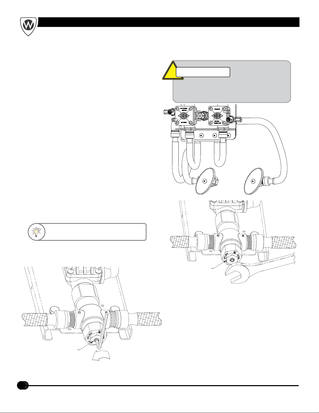
OPTIONAL MXTP VALVE INSTALLATION & ADJUSTMENT
!IMPORTANT
Flush supply lines of all foreign material such
as pipe dope, pipe chips, solder, sand etc.
before making up supply connections.
NOTE: Installation should be in accordance with
accepted plumbing practices.
1) Locate suitable place for mounting the valve
assembly. Valve assembly should be
accessible for service and adjustment and
as close to the point-of-use as possible.
Wall anchors and anchoring hardware are
by others.
2) Connect hot and cold water to supply
valve using 1/2" NPTE connections.
3) Connect outlet of tempering valve to
spout(s) using 1/4" O.D. tube connections
provided.
4) Turn on hot and cold water supplies. If any
leaks are observed, hand tighten
connections as necessary to stop leaks
before proceeding.
5) Turn on fixture and allow water to flow for 2
minutes. Measure water temperature at
outlet. If water is not at desired temperature,
adjust as necessary.
Valve Assembly Installation:
HINT: Angle stops are recommended
and is the responsibility of the installer.
NOTE: Factory set temperature is 105º F
1) Loosen locknut.
2) Turn on fixture and run water for at least 2
minutes. Allow supply temperature to
stabilize.
3) Turn temperature stem counter-clockwise
for hotter or clockwise for colder outlet
temperature.
4) Tighten locknut to prevent accidental or
unauthorized temperature adjustment.
5) Re-check outlet temperature.
Temperature Adjustment:
LOCKNUT
WARMER
TEMPERATURE
STEM
Phone (800) 782-7706 • Web: www.whitehallmfg.com
Table of contents