Whitehall P-10-S Operation and maintenance manual

E-27-S S-90-S
800-782-7706 • 626-968-6681 • www.whitehallmfg.com
INSTRUCTIONS FOR
OPERATION AND CARE OF
(Stationary Whirlpool)
P.O. Box 3527 • City of Industry, CA, 91744-0527, U.S.A.
Member of
6900-194-001_REV_A
Revised: April 23, 2019

4
34
3WHITEHALL MANUFACTURING • P.O. Box 3527 • City of Industry, CA 91744-0527 U.S.A.
Phone (800) 782-7706 • (626) 968-6681 • Fax (626) 855-4862 • Web: www.whitehallmfg.com
a
ŸWHIRLPOOLS intended for professional use only.
Ÿ230v WHIRLPOOLS for export only.
ŸDO NOT operate appliance without properly filling tub with water. Under no conditions should the appliance be operated without water.
Fill tub with water to the prescribed level before plugging turbine into an electrical receptacle. Operating the appliance without water may
result in damage to the motor.
ŸIMPROPER USE of the whirlpool can cause injury. Use the whirlpool only for the purpose described in this manual.
ŸTHE TURBINE is top-heavy. Improper handling can cause injury or damage. Handle the turbine with care.
ŸINCORRECT PARTS and service can cause injury to persons and damage equipment. Use only Whitehall parts and Whitehall approved
service on turbines. Contact Whitehall Customer Service.
ŸATTACHING IMPROPER items to the whirlpool can cause injury to persons and damage to equipment. Use only Whitehall approved
items on the whirlpools.
! !
PLEASE READ THIS ENTIRE
BOOKLET BEFORE OPERATING
YOUR NEW WHIRLPOOL
Failure to follow these instructions could result in damage
to your new whirlpool and/or bodily injury
European Union CE Mark
The presence of the CE Mark on the Whitehall turbine means that it has been designed, tested and certified as complying
with all applicable European Union regulations and recommendations.
Waste Electrical and Electronic Equipment (WEEE)
This symbol on the product or on its packaging indicates that this product must not be disposed of with regular waste.
Instead, it is the user’s responsibility to dispose of waste equipment according to the local laws. Separate collection and
recycling of the waste equipment at the time of disposal will help conserve natural resources and ensure it is recycled in a
manner that protects human health and the environment. For information about where the user can drop off the waste
equipment for recycling, please contact your local waste collection authority.
General Warning or Caution
The Exclamation Symbol appears in Warning and Caution statements. This symbol designates where personal injury or
damage to the equipment is possible.
Electric Shock
The Electric Shock Symbol is used to indicate a hazard arising from dangerous voltage. Any mishandling could result in
irreparable damage to the equipment and/or personal injury or death.
Hot Surface
This symbol is used to indicate a hot surface and to avoid prolonged contact with indicated surface.
Refer To Installation Manual
This symbol means refer to installation manual prior to performing any installation, operation or maintenance.
The Sine Wave
This symbol on the label indicates the turbine motor operates on alternating current at the listed cycles.
Figure of a Person
This image on the label indicates that the turbine contains a pump impeller, meeting definition of Type B Applied Part.
WARNING
To avoid electric shock, connect the turbine power cord to properly earth-grounded, GFCI protected,
3-prong receptacles only. Failure to observe this precaution can result in severe injury.

WHITEHALL MANUFACTURING • P.O. Box 3527 • City of Industry, CA 91744-0527 U.S.A.
Phone (800) 782-7706 • (626) 968-6681 • Fax (626) 855-4862 • Web: www.whitehallmfg.com
1
Thermometers ...........................................................................................................................Page 23
Cleaning & Disinfecting ....................................................................................................................Pages 24
Maintenance & Troubleshooting .......................................................................................................Pages 26
Turbine Information...........................................................................................................................Pages 27
Motor Raising & Lowering Assembly ........................................................................................Page 12
Motor Raising & Lowering Assembly (Slant Back) ....................................................................Page 13
Care & Cleaning ...............................................................................................................................Pages 25
General Knowledge..............................................................................................................................Page 2
Operating Skills & Training ..........................................................................................................Page 2
Patient Evaluation .......................................................................................................................Page 2
Inspecting Whirlpool ....................................................................................................................Page 2
Drain / Overflow Assembly - “H” & “S” Series............................................................................Page 14
Drain / Overflow Assembly - "E" Series .....................................................................................Page 15
Drain / Overflow Assembly - (Lo-Boy) .......................................................................................Page 16
Drain / Overflow Assembly - Podiatry Series.............................................................................Page 17
Drain / Overflow Assembly - Slant Back ....................................................................................Page 18
Separate Drain / Overflow Assembly - P-10, P/E-15/22 ............................................................Page 19
Separate Drain / Overflow Assembly - E-22-SP, E-27/45..........................................................Page 20
Separate Drain / Overflow Assembly - H-60/70/90, S-85/90 .....................................................Page 21
Butterfly Drain Valve ..................................................................................................................Page 22
Stationary Motor/Turbine Assembly.............................................................................................Page 9
Parts List ...................................................................................................................................Page 10
Motor Raising & Lowering Assembly (Small).............................................................................Page 11
Warning ................................................................................................................................................Page a
Using The Whirlpool .............................................................................................................................Page 3
Repair Parts and Replacement Turbines ......................................................................................Pages 9-23
Table of Contents
Table of Contents .................................................................................................................................Page 1
Installation & Operation ...................................................................................................................Pages 4-8
Fixture Installation Location Guide..............................................................................................Page 4
Stationary Style Hydrotherapy Whirlpool Dimensions.................................................................Page 5
Combined Drain / Overflow .........................................................................................................Page 6
Separate Drain / Overflow...........................................................................................................Page 7
Slant Back ...................................................................................................................................Page 8

General Knowledge
WHITEHALL MANUFACTURING • P.O. Box 3527 • City of Industry, CA 91744-0527 U.S.A.
Phone (800) 782-7706 • (626) 968-6681 • Fax (626) 855-4862 • Web: www.whitehallmfg.com
2
ŸBe trained on the use of the whirlpool and turbine.
TRAINING
Operator trainees need to:
ŸBe trained in hydrotherapy protocols.
ŸBe familiar with the types of patients who should or
should not receive this type of physical therapy (see
Patient Evaluation below).
ŸRead and understand this manual for the tub/turbine
combination.
ŸBecome familiar with the use of the whirlpool (bath and
turbine) before using with patient.
OPERATOR SKILLS AND TRAINING
Skills:
ŸA working knowledge of aquatic physical-therapy
procedures.
ŸThe ability to assist the patient.
Operators using the whirlpool tub/turbine set need:
PATIENT EVALUATION
Require Each Patient To Be Evaluated
The trained operator must evaluate and verify that each
patient is suitable for hydrotherapy treatment before
permitting the patient to begin hydrotherapy. If in doubt,
consult a medical professional before providing
hydrotherapy treatment.
Patients who are electrically-susceptible (patients with
exposed, non-waterproof electric leads, monitors, etc.),
patients carrying infectious disease, or patients with
certain other medical, mental or physical conditions should
not receive treatment with the whirlpool.
WARNING
!
INSPECTING THE WHIRLPOOL TUB AND TURBINE
Have your facility's equipment maintenance personnel
inspect the whirlpool regularly. Follow the checklist at right
and operate the whirlpool device through all its functions
as described in this manual.
ŸIs the thermometer present and is it legible?
ŸIs a properly-grounded and voltage-matched
hospital grade receptacle available for the turbine?
ŸCan the turbine be raised, lowered and locked at the
desired height?
Inspection Checklist
ŸDoes the drain valve open and close properly?
ŸIs the turbine located close enough to the electrical
outlet to prevent cord interference?
ŸAre all components present?
ŸIs the outlet equipped with a functioning GFCI (or
RCD) Residual-Current Device?
ŸDoes the turbine mount securely in place?
ŸDo the installed accessories operate without
interfering with tub use or turbine operation?
Important
BLOOD-BORNE DISEASE NOTICE: To reduce the
risk of exposure to blood-borne diseases such as HIV-1
and hepatitis when using the whirlpool, thoroughly read
and follow the disinfecting and cleaning instructions in
this manual.
Certain medical conditions are incompatible with
hydrotherapy. The trained operator is responsible for
determining each user’s suitability for hydrotherapy
before beginning treatment.
WARNING
!
WARNING
!
Untrained operators can cause injury or be injured.
Only trained personnel should operate the whirlpool.
WARNING
!
— Inspect the packaging for external signs of damage.
— Inspect the contents for damage.
If there is visible damage to the instrument upon receipt,
inform the shipping company and Whitehall immediately.
This Whitehall product has been carefully packaged at the
factory to minimize the possibility of damage during
shipping.
WARNING
!
Do not attempt to operate this equipment if there is
evidence of shipping damage or you suspect the unit
is damaged. Damaged equipment may present
additional hazards to you. Contact Whitehall technical
support for advice before attempting to plug in and
operate damaged equipment.
WARNING
!

Using The Whirlpool
WHITEHALL MANUFACTURING • P.O. Box 3527 • City of Industry, CA 91744-0527 U.S.A.
Phone (800) 782-7706 • (626) 968-6681 • Fax (626) 855-4862 • Web: www.whitehallmfg.com
3
USING THE WHIRLPOOL
ŸTo read and understand the information in this manual.
Operators using the whirlpool need:
Before Placing the Whirlpool Tub and Turbine
Combination In Service:
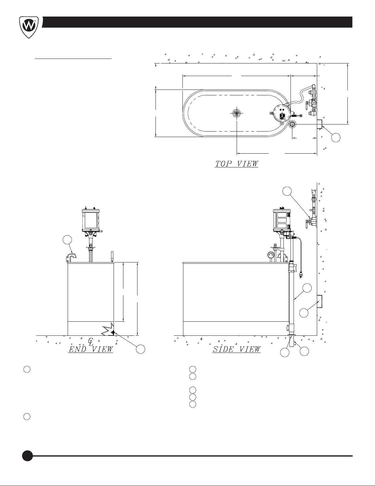
ŸTo have a plumbing professional install the whirlpool as
instructed in page 4. A rough-in Installing the Whirlpool,
drawing is available to assist the installer. Contact
Whitehall Customer Service, bottom of page, for any
additional information not covered in this manual.
ŸConfirm that the whirlpool operates properly. See
Inspecting the Whirlpool , page 2.
ŸMedical advice is beyond the scope of this manual.
ŸIt is the operator’s responsibility to ensure safe
practices for the patient and themselves.
ŸThe whirlpool is for professional use only. A minimum of
one trained operator is required.
ŸTurbine precautions:
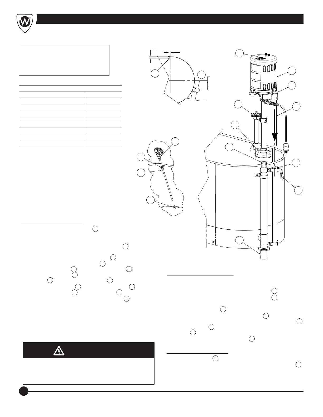
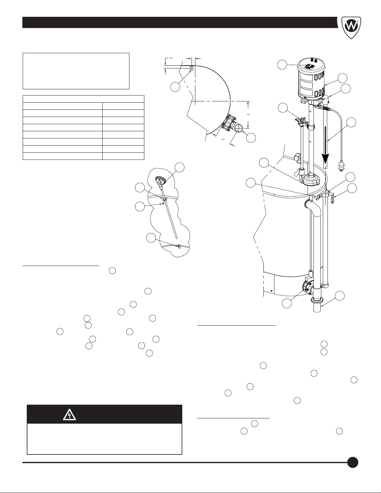
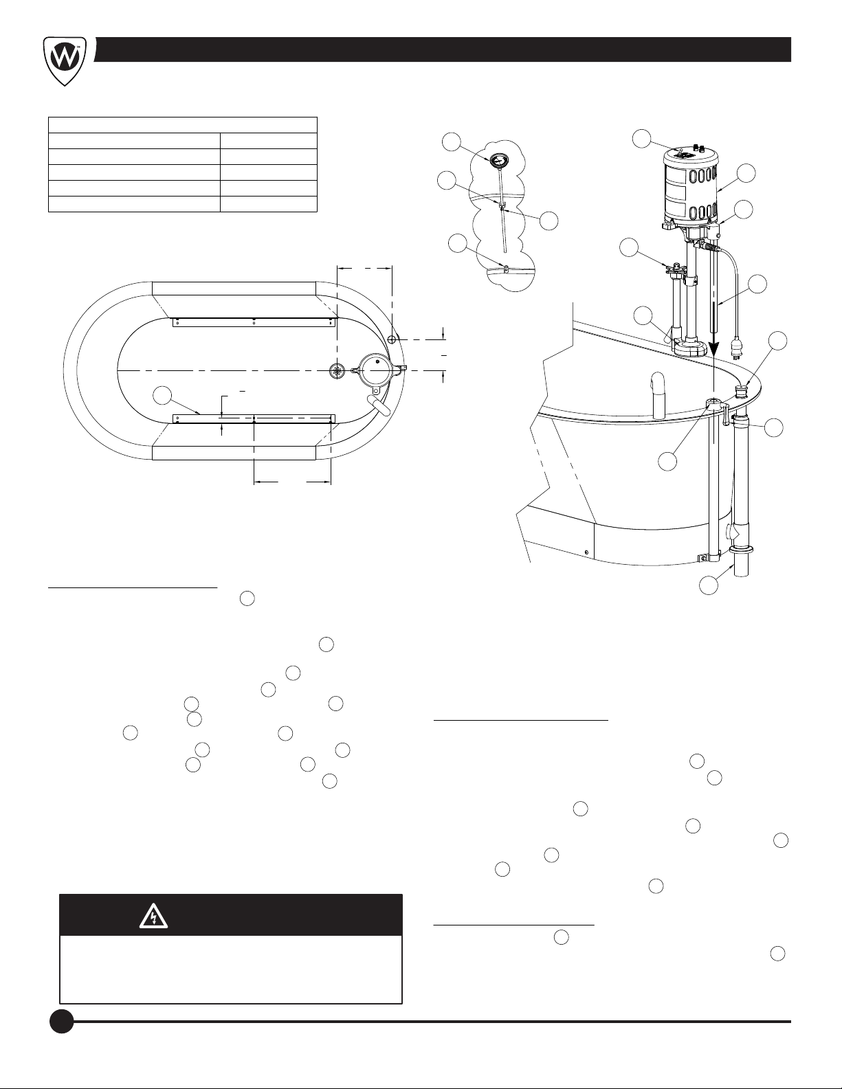
Ÿ Keep the area around the tub clear a minimum of 12"
(305mm) of clearance.
ŸThe trained operator must evaluate and verify that the
patient is suitable for hydrotherapy treatment before
beginning hydrotherapy with the whirlpool. See Patient
Evaluation, page 2.
ŸStay with patient at all times.
General Guidelines for Use:
Ÿ Cord plug is disconnect device. Always maintain clear
access to this connection after installation.
ŸFollow your state and local hydrotherapy procedures
and, if the patient has one, the physician's order for
treatment (see Patient Evaluation, page 2).
Plug the turbine cord only into a receptacle that is
voltage-matched, properly grounded and polarized.
Verify that the receptacle has GFCI protection.
Ÿ Keep patient hair, gown strings and other loose items
away from the impeller housing to avoid
entanglement and injury.
WARNING
!
Certain medical conditions are incompatible with
hydrotherapy. The trained operator is responsible for
determining each user's suitability for hydrotherapy
before beginning treatment.
Improper operation can cause injury. Operate the
whirlpool only as described in this manual.
Loose items such as gown straps or gauze can be
pulled into the turbine impeller and cause injury. Keep
loose items away from the turbine impeller housing.
An unattended patient can be injured. Stay with
patient at all times.
Important
Communicate with patient at all times. When the
turbine is used, tell the patient before starting or
stopping the turbine and before changing the water or
aeration level.
ŸAvoid prolonged contact with the motor cover, as
elevated temperatures can cause discomfort.
ŸRelative humidity 5 to 95% and atmospheric pressure sea
level to 3,000 meters during use.
ŸNormal Operating Conditions:
Temperature range between 50° and 93°F (10° and
35°C).
Transportation and Storage Conditions:
General Guidelines for Use: (Continued)
Ÿ Relative Humidity Range: 5 to 95%.
Ÿ Prior to unpacking, when new, tipping has no effect.
However, after assembly, the equipment should
remain upright, as tipping or inversion may cause
damage from components coming loose.
Ÿ Temperature Range should remain between 32° and
110°F (0° and 43°C)
Ÿ Room Atmospheric Pressure sea level to 3,000
meters.
Device Intended Use:
Whitehall Whirlpool turbines are intended to provide
clinical, physical hydro-massage treatment within a fluid
medium, mounted in a tank of a size and shape as
deemed effective and determined by a medical
professional.

Fixture Installation Location Guide
WHITEHALL MANUFACTURING • P.O. Box 3527 • City of Industry, CA 91744-0527 U.S.A.
Phone (800) 782-7706 • (626) 968-6681 • Fax (626) 855-4862 • Web: www.whitehallmfg.com
4
7
'L'-CLIPS FOR FLOOR MOUNTING
6
5
4
4
1
FURNISHED BY WHITEHALL
2" COMBINATION DRAIN AND OVERFLOW ASSEMBLY
2" DRAIN
OVER RIM INLET
2" x 5" TAIL PIECE FURNISHED WITH UNIT
THERMOSTATIC MIXING VALVES ARE OPTIONAL
TURBINE FOR ELECTRICAL REQUIREMENTS. AT WALL
ELECTRICAL REQUIREMENTS: REFER TO SPECIFIC
PROVIDE ONE HOSPITAL GRADE 3 POLE RECEPTACLE
12"
(305)
REC. MIN.
12"
(305)
REC. MIN.
1
2
3
4
5
6
7
DIMENSION DESCRIPTION
"D"
"OH"
"CW"
"L"
CD
"W"
"L" = LENGTH (ID)
"W" = WIDTH (ID)
"D" = DEPTH (ID)
"OH" = OVERALL HEIGHT
"CW" = CENTER OF TANK TO WALL
"CD" = CENTER OF DRAIN TO WALL
REFER TO PAGE 5 FOR DIMENSIONS
11"
(279)
MIN.
1
WITH GROUND FAULT INTERRUPT FOR TURBINE.
NOTES:
NOTE:
ENSURE ELECTRICAL RECEPTACLE IS AS CLOSE AS
POSSIBLE TO THE TURBINE.
2
(REFER TO SUPPLEMENTAL DRAWING FOR DETAILS)

Stationary Style Hydrotherapy Whirlpool Dimensions
WHITEHALL MANUFACTURING • P.O. Box 3527 • City of Industry, CA 91744-0527 U.S.A.
Phone (800) 782-7706 • (626) 968-6681 • Fax (626) 855-4862 • Web: www.whitehallmfg.com
5
REFER TO PAGE 4 FOR LAYOUT INFORMATION
25" (635)
34" (864)
"OH" DIM"D" DIM"W" DIM"L" DIM
INCHES (MM)
26-1/2" (673)
29" (737)
40" (1016)
45" (1143)
38" (965)
33" (838)
30" (762)
20" (508)
28" (711)
25-1/2" (648)
23" (584)22" (559)
36" (914)
42" (1067)
48" (1219)
52" (1321)
60" (1524)
66" (1676)
46" (1168)
56" (1422)
13" (330) 12" (305)
15" (381)
18" (457)
21" (533)
24" (610)
27" (686)
31" (787)
"CD" DIM"CW" DIM
26" (660)24" (610)18" (457)28" (711)
E-15-S
P-22-S
S-110-S
S-90-S
S-85-S
L-105-S
L-90-S
L-75-S
H-105-S
H-90-S
H-75-S
H-60-S
E-22-SP
E-45-S
E-27-S
E-22-S
P-15-S
P-10-S
MODEL NUMBER
WHITEHALL
S-85-SL
S-90-SL
S-110-SL
35" (889) 17" (432) N/A
N/A
N/A
32" (813)E-36-S
INCHES (MM) INCHES (MM) INCHES (MM) INCHES (MM) INCHES (MM)
26-1/2" (673)
26-1/2" (673)
26-1/2" (673)
26-1/2" (673)
26-1/2" (673)
26-1/2" (673)
26-1/2" (673)
26-1/2" (673)
13" (330)
13" (330)
15" (381)
15" (381)
15" (381)
15" (381)
15" (381)
15" (381)
15" (381) 21" (533)
28" (711)
28" (711)
28" (711)
28" (711)
28" (711)
28" (711)
28" (711)
28" (711)
18" (457)
18" (457)
18" (457)
18" (457)
18" (457)
24" (610)
24" (610)
24" (610)
24" (610)
24" (610)
24" (610)
24" (610)
24" (610)
24" (610)
24" (610)
24" (610)
25-1/2" (648)25" (635)
25" (635)
25" (635)
25" (635)
25" (635)
25" (635)
25" (635)
26" (660)
26" (660)
26" (660)21" (533)
34" (864)
34" (864)
34" (864)
34" (864)
20" (508)
20" (508)
20" (508)
20" (508)
20" (508)
25" (635)
25" (635)32" (813)
31" (787)
31" (787)
31" (787)
31" (787)
31" (787)
31" (787)
31" (787)
36" (914)
29" (737)
29" (737)
29" (737)
42" (1067)
31" (787)
31" (787)
36" (914)
48" (1219)
48" (1219)
48" (1219)
26" (660)
17" (432)
17" (432)
35" (889)
35" (889)
35" (889)
46" (1168)
56" (1422)

WHITEHALL MANUFACTURING • P.O. Box 3527 • City of Industry, CA 91744-0527 U.S.A.
Phone (800) 782-7706 • (626) 968-6681 • Fax (626) 855-4862 • Web: www.whitehallmfg.com
6
Installation Instructions
WARNING
Turbine assembly is provided with a 3-way plug. The
third prong functions as a built-in ground and must be
plugged into a matching grounded GFCI receptacle to
properly ground the product.
WARNING
NOTE: THESE INSTALLATION
INSTRUCTIONS ARE USED FOR ALL
WHITEHALL STATIONARY ALL MODELS
WITH STANDARD DRAIN & OVERFLOW
ASSEMBLIES
COMPLETELY LUBRICATE THE PLUNGER ASSEMBLY.
E-
CLOCKWISE, THEN FULLY COUNTERCLOCKWISE TO
HANDLE 5 . INTERNAL BUSHING MAY NEED ADJUSTMENT.
7
B-
A-
LEVEL OF AGITATION AND PRESSURE.
E-
UNTIL THE PUMP 12 IS AT THE DESIRED LOCATION. TIGHTEN
PUSHING DOWN ON TOP OF THE MOTOR SUPPORT CASTING 14
D-
C-
CLOCKWISE, THIS PROVIDES MAX PRESSURE AND AGITATION.
B-
WATER LEVEL SHOULD BE A MAXIMUM OF 4" BELOW THE RIM
A-
INTO LOWER BRACKET 9 , TIGHTEN SCREW 10 .
D-
ASSEMBLY 4 AND TIGHTENING HANDLE 5 .
MOTOR SUPPORT ROD 6 INTO RAISING AND LOWERING
LOWERING ASSEMBLY 4 BY LOOSENING HANDLE 5 , SLIDING
C-
A-
(SEE DETAIL A) NOTE: FOR INFORMATION ON OPTIONAL
THERMOSTATIC MIXING VALVE CONTACT FACTORY.
B-
2
10
3
4
5
6
9
TURN THE PRESSURE CONTROL VALVE HANDLE 11 FULLY
LIFT COMBINATION DRAIN & OVERFLOW ASSEMBLY HANDLE 15 .
TURN OFF SWITCH 13 .
ADJUST PRESSURE CONTROL VALVE 11 TO DELIVER DESIRED
ADJUST RAISING AND LOWERING ASSEMBLY 4 BY SLOWLY
TURN ON THE SWITCH 13 .
TURN THE PRESSURE CONTROL VALVE HANDLE 11 FULLY
FILL TUB AS DESIRED USING THERMOSTATIC MIXING VALVE.
INSTALL THERMOMETER 7 THRU UPPER BRACKET 8 AND
INSTALL MOTOR/TURBINE ASSEMBLY 3 INTO RAISING AND
ROUGH-IN FOR 2" OD DRAIN LINE 1 AND WATER INLET VALVE.
LOCATE TANK AND SECURE WITH "L" BRACKETS 2 , WITH
8
F-
REFERENCE DRAWINGS
ASSEMBLIES
RAISING & LOWERING "E" & "P"
MOTOR/TURBINE 9/10
11
PAGE NUMBER
15
14
DRAIN OVERFLOW - "E"
DRAIN OVERFLOW - "H" & "S"
5"
21
4"
3
4"1"
PROVIDE ELECTRICAL SERVICE AND PROPERLY INSTALLED,
GROUND FAULT CIRCUIT INTERRUPTER (GFCI) FOR MOTOR
SPECIFIED. MOTOR SPECIFICATIONS AVAILABLE ARE EITHER
120V AC / 60 HZ ON 15A CIRCUIT OR 240 V AC / 50 HZ ON 10A
AND A MINIMUM OF 6" ABOVE BOTTOM OF PUMP 12 .
ASSEMBLY PROCEDURE:
OPERATION PROCEDURE:
DRAINING PROCEDURE:
INSTALLER PROVIDED FLOOR ANCHORS AND ANCHORING
HARDWARE. MAKE WASTE CONNECTIONS 1 .
1
1
11
12
13
14
15
DETAIL "A"
(TOP VIEW)
C
L
RAISING & LOWERING 12
DRAIN OVERFLOW - "L"
19DRAIN OVERFLOW - "P"
16
THERMOMETER 23

Installation Instructions; -SDO Separate Drain OverflowInstallation Instructions; -SDO Separate Drain Overflow
WHITEHALL MANUFACTURING • P.O. Box 3527 • City of Industry, CA 91744-0527 U.S.A.
Phone (800) 782-7706 • (626) 968-6681 • Fax (626) 855-4862 • Web: www.whitehallmfg.com
7
WARNING
Turbine assembly is provided with a 3-way plug. The
third prong functions as a built-in ground and must be
plugged into a matching grounded GFCI receptacle to
properly ground the product.
WARNING
COMPLETELY LUBRICATE THE PLUNGER ASSEMBLY.
E-
CLOCKWISE, THEN FULLY COUNTERCLOCKWISE TO
HANDLE 5 . INTERNAL BUSHING MAY NEED ADJUSTMENT.
7
B-
A-
LEVEL OF AGITATION AND PRESSURE.
E-
UNTIL THE PUMP 12 IS AT THE DESIRED LOCATION. TIGHTEN
PUSHING DOWN ON TOP OF THE MOTOR SUPPORT CASTING 14
D-
C-
CLOCKWISE, THIS PROVIDES MAX PRESSURE AND AGITATION.
B-
WATER LEVEL SHOULD BE A MAXIMUM OF 4" BELOW THE RIM
A-
INTO LOWER BRACKET 9 , TIGHTEN SCREW 10 .
D-
ASSEMBLY 4 AND TIGHTENING HANDLE 5 .
MOTOR SUPPORT ROD 6 INTO RAISING AND LOWERING
LOWERING ASSEMBLY 4 BY LOOSENING HANDLE 5 , SLIDING
C-
A-
(SEE DETAIL A) NOTE: FOR INFORMATION ON OPTIONAL
THERMOSTATIC MIXING VALVE CONTACT FACTORY.
B-
2
10
3
4
5
6
9
TURN THE PRESSURE CONTROL VALVE HANDLE 11 FULLY
TURN HANDLE 15 CLOCKWISE TO OPEN DRAIN VALVE 16 .
TURN OFF SWITCH 13 .
ADJUST PRESSURE CONTROL VALVE 11 TO DELIVER DESIRED
ADJUST RAISING AND LOWERING ASSEMBLY 4 BY SLOWLY
TURN ON THE SWITCH 13 .
TURN THE PRESSURE CONTROL VALVE HANDLE 11 FULLY
FILL TUB AS DESIRED USING THERMOSTATIC MIXING VALVE.
INSTALL THERMOMETER 7 THRU UPPER BRACKET 8 AND
INSTALL MOTOR/TURBINE ASSEMBLY 3 INTO RAISING AND
ROUGH-IN FOR 2" OD DRAIN LINE 1 AND WATER INLET VALVE.
LOCATE TANK AND SECURE WITH "L" BRACKETS 2 , WITH
8
F-
REFERENCE DRAWINGS
ASSEMBLIES
RAISING & LOWERING - "E" & "P"
MOTOR/TURBINE 9/10
11
PAGE NUMBER
15
14
DRAIN OVERFLOW - "E"
RAIN OVERFLOW - "H" & "S"
PROVIDE ELECTRICAL SERVICE AND PROPERLY INSTALLED,
GROUND FAULT CIRCUIT INTERRUPTER (GFCI) FOR MOTOR
SPECIFIED. MOTOR SPECIFICATIONS AVAILABLE ARE EITHER
120V AC / 60 HZ ON 15A CIRCUIT OR 240 V AC / 50 HZ ON 10A
AND A MINIMUM OF 6" ABOVE BOTTOM OF PUMP 12 .
ASSEMBLY PROCEDURE:
OPERATION PROCEDURE:
DRAINING PROCEDURE:
INSTALLER PROVIDED FLOOR ANCHORS AND ANCHORING
HARDWARE. MAKE WASTE CONNECTIONS 1 .
1
1
11
12
13
14
15
DETAIL "A"
(TOP VIEW)
C
L
RAISING & LOWERING 12
17DRAIN OVERFLOW - "P"
THERMOMETER 23
31
2"
1"
3
4"
77
8"
16
NOTE: THESE INSTALLATION
INSTRUCTIONS ARE USED FOR ALL
WHITEHALL STATIONARY ALL MODELS
WITH -SDO SEPARATE DRAIN & OVERFLOW
ASSEMBLIES

WARNING
Turbine assembly is provided with a 3-way plug. The
third prong functions as a built-in ground and must be
plugged into a matching grounded GFCI receptacle to
properly ground the product.
WARNING
Installation Instructions; Slant Back
WHITEHALL MANUFACTURING • P.O. Box 3527 • City of Industry, CA 91744-0527 U.S.A.
Phone (800) 782-7706 • (626) 968-6681 • Fax (626) 855-4862 • Web: www.whitehallmfg.com
8
COMPLETELY LUBRICATE THE PLUNGER ASSEMBLY.
E-
CLOCKWISE, THEN FULLY COUNTERCLOCKWISE TO
HANDLE 5 . INTERNAL BUSHING MAY NEED ADJUSTMENT.
B-
A-
LEVEL OF AGITATION AND PRESSURE.
E-
UNTIL THE PUMP 12 IS AT THE DESIRED LOCATION. TIGHTEN
PUSHING DOWN ON TOP OF THE MOTOR SUPPORT CASTING 14
D-
C-
CLOCKWISE, THIS PROVIDES MAX PRESSURE AND AGITATION.
B-
WATER LEVEL SHOULD BE A MAXIMUM OF 4" BELOW THE RIM
A-
INTO LOWER BRACKET 9 , TIGHTEN SCREW 10 .
D-
ASSEMBLY 4 AND TIGHTENING HANDLE 5 .
MOTOR SUPPORT ROD 6 INTO RAISING AND LOWERING
LOWERING ASSEMBLY 4 BY LOOSENING HANDLE 5 , SLIDING
C-
A-
(SEE DETAIL A) NOTE: FOR INFORMATION ON OPTIONAL
THERMOSTATIC MIXING VALVE CONTACT FACTORY.
B-
TURN THE PRESSURE CONTROL VALVE HANDLE 11 FULLY
LIFT COMBINATION DRAIN & OVERFLOW ASSEMBLY HANDLE 15 .
TURN OFF SWITCH 13 .
ADJUST PRESSURE CONTROL VALVE 11 TO DELIVER DESIRED
ADJUST RAISING AND LOWERING ASSEMBLY 4 BY SLOWLY
TURN ON THE SWITCH 13 .
TURN THE PRESSURE CONTROL VALVE HANDLE 11 FULLY
FILL TUB AS DESIRED USING THERMOSTATIC MIXING VALVE.
INSTALL THERMOMETER 7 THRU UPPER BRACKET 8 AND
INSTALL MOTOR/TURBINE ASSEMBLY 3 INTO RAISING AND
ROUGH-IN FOR 2" OD DRAIN LINE 1 AND WATER INLET VALVE.
LOCATE TANK AND SECURE WITH "L" BRACKETS 2 , WITH
F-
REFERENCE DRAWINGS
ASSEMBLIES
RAISING/LOWERING
MOTOR/TURBINE 9/10
13
PAGE NUMBER
23
DRAIN OVERFLOW
PROVIDE ELECTRICAL SERVICE AND PROPERLY INSTALLED,
GROUND FAULT CIRCUIT INTERRUPTER (GFCI) FOR MOTOR
SPECIFIED. MOTOR SPECIFICATIONS AVAILABLE ARE EITHER
120V AC / 60 HZ ON 15A CIRCUIT OR 240 V AC / 50 HZ ON 10A
AND A MINIMUM OF 6" ABOVE BOTTOM PUMP 12 .
ASSEMBLY PROCEDURE:
OPERATION PROCEDURE:
DRAINING PROCEDURE:
INSTALLER PROVIDED FLOOR ANCHORS AND ANCHORING
HARDWARE. MAKE WASTE CONNECTIONS 1 .
18
THERMOMETER
67
8"
17"
TYP.
11
4"
TYP.
121
8"
13
11
12
6
14
3
15
5
4
1
2
7
8
10
9
DETAIL "A"
(TOP VIEW)

Stationary Motor/Turbine Assembly
WHITEHALL MANUFACTURING • P.O. Box 3527 • City of Industry, CA 91744-0527 U.S.A.
Phone (800) 782-7706 • (626) 968-6681 • Fax (626) 855-4862 • Web: www.whitehallmfg.com
9
SEE PAGE 10 FOR PART DESCRIPTION
13
12
11
10
9
8
7
6
22
5
4
3
2
23
25
26
21
20
19
18
17
16
15
14
34
35
32
30
29A
28
42
27
41
40
39
38
37
36
24
1
29P
31
33
43B
44
43A
45

Stationary Repair Parts List
WHITEHALL MANUFACTURING • P.O. Box 3527 • City of Industry, CA 91744-0527 U.S.A.
Phone (800) 782-7706 • (626) 968-6681 • Fax (626) 855-4862 • Web: www.whitehallmfg.com
10
1
6502-307-000 #8-32 x 1/2" PHIL FLAT HD SELF-TAP SCREW2
6504-501-199 17" PUMP GASKET3
6525-518-000 TURBINE IMPELLER - PLASTIC4
5 6502-401-000 1/4"-20 x 5/16" HEX SOCKET SET SCREW
6
7
8
9
10
11
12
13
14
15
16
17
19
20
21
22
23
24
25
26
27
28
29I
ITEM PART NUMBER DESCRIPTION ITEM PART NUMBER DESCRIPTION
18
E-15-S
E-22-S
E-22-SP
E-27-S
H-90-S
H-75-S
H-60-S
E-45-S
L-75-S
H-105-S
L-90-S
P-10-S
L-105-S
P-15-M-SDP
S-85-M-SDP
P-22-M-SDP
S-90-M-SDP
S-110-S
E-36-S
L-90-SL
L-105-SL
WHITEHALL MODEL
NUMBERS
THESE REPLACEMENT TURBINES ARE USED FOR THE
FOLLOWING MODEL NUMBERS:
S-110-M-SDP
S-85-S
S-90-S
P-15-S
P-22-S
L-75-M-SDP
L-90-M-SDP
L-105-M-SDP
H-90-M-SDP
H-75-M-SDP
H-60-M-SDP
H-105-M-SDP
E-15-M-SDP
E-22-M-SDP
E-27-M-SDP
E-45-M-SDP
E-36-M-SDP
SB-100-S
WHITEHALL MODEL
NUMBERS
WHITEHALL MODEL
NUMBERS
30
31
32
SEE CHART IMPELLER SHAFT HOUSING TUBE
33
34
35
SEE CHART COMPLETE TURBINE ASSEMBLY
6
PLUNGER ASSEMBLY
12 IMPELLER SHAFT
17
IMPELLER SHAFT HOUSING TUBE
27
MOTOR BASE
31
RAISING & LOWERING ROD
1
SPECIFY MODEL
COMPLETE TURBINE ASSEMBLY
0341-101-000 COTTER PIN
6502-042-000 1/4"-20 x 5/8" PHIL PAN HEAD SCREW
6502-300-000 #8-32 x 3/8" PHIL FLAT HD SELF-TAP SCREW
6525-514-199 SHAFT BEARING
6502-410-000 1/4"-20 x 1/4" DOG SET SCREW
6502-352-000 3/8"-16 x 3" HEX CAP SCREW
6502-402-000 5/16"-18 x 1/4" HEX SOCKET SET SCREW
6525-605-001 PLASTIC MOTOR COVER ASSEMBLY
6505-025-000 DPST TOGGLE SWITCH
6505-035-000 WATERPROOF TOGGLE SWITCH CAP
6502-452-000 3/8"-16 x 3/4" HEX SOCKET CAP SCREW
6505-030-003 10 FEET, 115VAC, 60Hz GFI POWER CORD
6525-513-199
6525-584-199 HANDLE
6531-112-199 TENSION ADJUSTER
6531-111-199 FRICTION LOCK ROD
6531-113-000 SPRING
6525-570-199 AIR RING BRACKET
6502-620-000 1-3/8" RETAINING RING
6504-022-000 O-RING
6502-413-000 1/4"-20 x 5/16" DOG SET SCREW
6525-509-001 PUMP BODY / COVER ASSEMBLY
6525-509-299 PUMP COVER
6525-510-299 PUMP BODY
6505-034-003 DOMESTIC GFI POWER CORD 220VAC
6505-043-003 RUSSIAN GFI POWER CORD, 250VAC
6505-074-003 INDIA/S. AFRICA GFI POWER CORD, 230VAC
6505-043-003 EUROPEAN GFI POWER CORD, 250VAC
6505-073-003 UK GFI POWER CORD, 230VAC
6505-070-003 ISRAEL GFI POWER CORD, 250VAC
6505-071-003 AUSTRALIAN GFI POWER CORD, 250VAC
SHAFT COUPLING
SEE CHART PLUNGER ASSEMBLY
SEE CHART IMPELLER SHAFT
SEE CHART MOTOR BASE
SEE CHART RAISING & LOWERING ROD
6502-402-000 1/4"-20 x 5/16" PHIL PAN HD SCREW
29J
29K
29L
29M
29N
29O
29P
0206-003-000 5/16"-18 UNC x 5/8" HEX CAP SCREW
37
1/2 HP TURBINE MOTOR
1/2 HP TURBINE MOTOR SEE CHART
0126-199-000 #8-32 x 3/8 TORX BUTTON HD SCREW36
37 6525-507-199 COUPLING SLEEVE
38
39
40
41
6505-015-001 CAPACITOR ASSEMBLY
6525-504-199 CAPACITOR COVER42
6525-520-001 FLEXIBLE STRAIN RELIEF ASSEMBLY
6525-608-00043A
6525-607-000 FUSE HOLDER44
REPLACEMENT
TURBINE ASSEMBLY
TA-15-S-T1
REPLACEMENT
TURBINE ASSEMBLY
REPLACEMENT
TURBINE ASSEMBLY
TA-18-S-T1-RS1
TA-21-S-T1
TA-25-S-T1
TA-28-S-T1
TA-28-S-T1
TA-18-S-T1-RS2
P-10-M-SDP TA-12-S-T1
TA-15-S-T1
TA-18-S-T1-RS1
TA-25-S-T1
TA-21-S-T1
6525-612-00043B
1/4" OD- 12.5A - 250VAC FUSE
1/4" OD- 8A - 250VAC FUSE
0337-050-000 1/4" LOCK WASHERS45
(110VAC TURBINE)
(220VAC TURBINE)
29A 6505-030-000 10 FEET, 115VAC, 60Hz POWER CORD
6505-034-001 DOMESTIC POWER CORD 220VAC
6505-043-001 RUSSIAN POWER CORD, 250VAC
29B
29C
6505-074-001 INDIA/S. AFRICA POWER CORD, 230VAC
6505-043-001 EUROPEAN POWER CORD, 250VAC
6505-073-001 UK POWER CORD, 230VAC
6505-070-001 ISRAEL POWER CORD, 250VAC
6505-071-001 AUSTRALIAN POWER CORD, 250VAC
29D
29E
29F
29G
29H

Motor Raising & Lowering Assembly (Small)
WHITEHALL MANUFACTURING • P.O. Box 3527 • City of Industry, CA 91744-0527 U.S.A.
Phone (800) 782-7706 • (626) 968-6681 • Fax (626) 855-4862 • Web: www.whitehallmfg.com
11
7
8
9 4
5
6
10
11
12 3B
2B
14
6
8
13
R & L ASSY P/E-22-S
R & L ASSY P/E-15-S
R & L ASSY P-10-S
1D
1B
1A
3A
2A
2C
3C
ITEM PART NUMBER DESCRIPTION ITEM PART NUMBER DESCRIPTION
E-15-S
E-22-S
E-22-SP
WHITEHALL MODEL NUMBERS
THESE REPAIR PARTS ARE USED
FOR THE FOLLOWING MODEL
NUMBERS ONLY:
P-10-S
P-22-S
P-15-SE-22-MU
R & L ASSY P/E-22-MU/SP
1C
2D
3D
1A 6530-015-001 3/4" DIM. R & L ASSEMBLY - P-10-S
1B 6530-025-001 3/4" DIM. R & L ASSEMBLY - P/E-15-S
1C 6530-030-001 3/4" DIM. R & L ASSEMBLY - P/E-22-MU/SP
1D 6530-045-001 3/4" DIM. R & L ASSEMBLY - P/E-22-S
2A 6509-205-199 1-1/8" DIA. x 12-1/8" TUBE - P-10-S
2B 6509-215-199 1-1/8" DIA. x 18" TUBE - P/E-15-S
2C 6509-215-199 1-1/8" DIA. x 18" TUBE - P/E-22-MU/SP
2D 6509-225-199 1-1/8" DIA. x 20" TUBE - P/E-22-S
3A 6503-005-000 7/8" DIA. x 13" SPRING - P-10-S
3B 6503-015-000 7/8" DIA. x 9" SPRING - P/E-15-S
3C 6503-015-000 7/8" DIA. x 9" SPRING - P/E-22-MU/SP
3D 6503-030-000 7/8" DIA. x 23" SPRING - P/E-22-S
4 6530-110-199 END CAP
5 6502-411-000 1/4"-20 x 5/16" ALLEN HEAD SET SCREW
6 6502-200-000 1/4"-20 x 5/8" PHILLIPS TRUSS HEAD SCREW
7 6530-100-199 UPPER BRACKET
8 0337-050-000 1/4" STAINLESS STEEL LOCKWASHER
9 6502-520-000 1/4"-20 HIGH CROWN ACORN NUT
10 6530-111-199 HANDLE
11 6530-112-199 BUSHING
12 6530-114-199 STUD
13 0302-005-000 1/4"-20 HEX NUT
14 6530-101-199 LOWER BRACKET

Motor Raising & Lowering Assembly
WHITEHALL MANUFACTURING • P.O. Box 3527 • City of Industry, CA 91744-0527 U.S.A.
Phone (800) 782-7706 • (626) 968-6681 • Fax (626) 855-4862 • Web: www.whitehallmfg.com
12
7
8 4
5
6
9
10
11
13
6
12 2E
3E
2F
3F
3D
2D
3A
3C
3B
2A
2C
2B
ITEM PART NUMBER DESCRIPTION ITEM PART NUMBER DESCRIPTION
1C
1B
1A R & L ASSY E-27-S
R & L ASSY E-45-/S-85/90/110-S
R & L ASSY H-60/75/90/105-S 1E
1F1D R & L ASSY L-75/90/105-S
R & L ASSY L-75/90/105-M/SL
R & L ASSY H-60/75/90/105-S
E-27-S
E-36-S
WHITEHALL MODEL NUMBERS
THESE REPAIR PARTS ARE USED
FOR THE FOLLOWING MODEL
NUMBERS ONLY:
H-60-S
H-90-S
H-75-S
H-105-S
L-75-M
L-75-S
L-90-M
L-105-M
L-90-S
L-105-S
S-85-S
S-85-SL
S-90-S
S-110-S
S-90-SL
S-110-SL
L-75-M-SDP
L-75-SL
L-90-M-SDP
L-90-SL
L-105-M-SDP
L-105-SL
S-90-M
S-110-M-SDP
S-110-M
S-90-M-SDP
S-85-M-SDP
S-85-M
E-45-S
1A 6530-220-001 1" DIA. R & L ASSY - E-27-S
1B 6530-235-001 1" DIA. R & L ASSY - E-45/S-85/90/110-S
1C 6530-245-001 1" DIA. R & L ASSY - H-60/75/90/105-S
1D 6530-215-001 1" DIA. R & L ASSY - L-75/90/105-S
1E 6530-210-001 1" DIA. R & L ASSY - L-75/90/105-M/SL
1F 6530-225-001 1" DIA. R & L ASSY - E-45-SL/S-85/90/110-M/SL
2A 6509-265-199 1-3/8" DIA. x 23-1/2" TUBE - E-27-S
2B 6509-275-199 1-3/8" DIA. x 27-1/4" TUBE - E-45/S-85/90/110-S
2C 6509-280-199 1-3/8" DIA. x 30-1/2" TUBE - H-60/75/90/105-S
2D 6509-260-199 1-3/8" DIA. x 21-1/4" TUBE - L-75/90/105-S
2E 6509-255-199 1-3/8" DIA. x 18-1/2" TUBE - L-75/90/105-M/S
2F 6509-255-199 1-3/8" DIA. x 18-1/2" TUBE - S-85/90/110-M/SL
3A 6503-265-000 1-1/8" x 23-1/2" SPRING - E-27-S
3B 6503-070-000 1-1/8" x 30-1/2" SPRING - E-45/S-85/90/110-S
3C 6503-075-000 1-1/8" x 34" SPRING - H-60/75/90/105-S
3D 6503-060-000 1-3/8" x 23-1/2" SPRING - L-75/90/105-S
3E 6503-055-000 1-18" x 19" SPRING - L-75/90/105-M/S
3F 6503-065-000 1-18" x 27" SPRING - S-58/90/110-M/SL
4 6530-310-199 END CAP
5 6502-411-000 SET SCREW
6 6502-200-000 1/4"-20 x 5/8" PHILLIPS TRUSS HD SCREW
7 6530-300-199 UPPER BRACKET
8 6502-520-000 1/4"-20 HIGH CROWN ACORN NUT
9 6530-111-199 HANDLE
10 6530-112-199 BUSHING
11 6530-114-199 STUD
12 0302-005-000 1/4"-20 HEX NUT
13 6530-301-199 LOWER BRACKET

ITEM PART NUMBER DESCRIPTION ITEM PART NUMBER DESCRIPTION
SCALED x 1-1/2
1
6
5
4
3
8
7
2
11
910
7
12
1 6530-260-001 R & L ASSEMBLY
2 6502-401-000 1/4"-20 x 5/16 SET SCREW
3 6530-411-199 LOCKING HUB
4 6530-114-199 3/8"-16 UNC STUD
5 6530-112-199 BUSHING
6 6530-111-199 LOCKING HANDLE
7 0116-104-000 1/4"-20 x 1/2" PHILLIPS ROUND HEAD SCREW
8 6530-310-199 END CAP
9 6530-520-000 1/4"-20 STAINLESS STEEL ACORN NUT
10 6530-301-199 LOWER BRACKET
11 6509-265-199 1-3/8" DIA. x 23-1/2" R & L TUBE
12 6503-065-000 1-1/8" DIA. x 27" SPRING
Motor Raising & Lowering Assembly (Slant Back)
WHITEHALL MANUFACTURING • P.O. Box 3527 • City of Industry, CA 91744-0527 U.S.A.
Phone (800) 782-7706 • (626) 968-6681 • Fax (626) 855-4862 • Web: www.whitehallmfg.com
13

3
6
7
8
5
1A 1B 1C 1D 1E 1F
9
10 16
13
15
23
2526
24
17
1820 19
14
22
21
30
27
31
12
14
11
2B2A 4 5
ITEM PART NUMBER DESCRIPTION ITEM PART NUMBER DESCRIPTION
28 29
2A
1A 6531-010-001 DRAIN & OVERFLOW - H-60-S
1B 6531-012-001 DRAIN & OVERFLOW - H-75-S
1C 6531-011-001 DRAIN & OVERFLOW - H-90/105-S
1D 6531-015-001 DRAIN & OVERFLOW - S-85-S
1E 6531-014-001 DRAIN & OVERFLOW - S-90-S
1F 6531-016-001 DRAIN & OVERFLOW - S-110-S
2A 6509-346-199 2" O.D. x 17-3/4" DRAIN TUBE - H-60-S
2B 6509-360-199 2" O.D. x 20-3/8" DRAIN TUBE - H-75-S
3 6509-370-199 2" O.D. x 23-5/8" DRN TUBE - H-90/105-S/-85-S
4 6509-365-199 2" O.D. x 22-3/8" DRAIN TUBE - S-90-S
5 6509-385-199 2" O.D. x 27-1/2" DRAIN TUBE - S-110-S/HI-BOY
6 6508-000-199 DRAIN ELBOW
7 6504-500-000 DRAIN GASKET
8 6508-050-199 STRAINER
9 6508-010-199 DRAIN TEE
10 6509-375-199 2" O.D. x 24" DRAIN TUBE - SPORTS
11 6531-056-001 33-1/4" OVERFLOW ASSEMBLY - HI-BOY
12 6531-055-001 29-5/8" OVERFLOW ASSEMBLY
13 6531-102-199 HANDLE
14 6502-450-000 #8-32 x 3/8" PHILLIPS PAN HEAD SCREW
15 6531-110-001 FRICTION LOCK ASSEMBLY
16 6531-100-001 OVERFLOW BRACE
17 0337-050-000 1/4" STN STL HELICAL LOCKWASHER
18 6502-103-000 #8-32 x 1/4" PHILLIPS PAN HEAD SCREW
19 6502-200-000 1/4"-20 x 5/8" PHILLIPS TRUSS HEAD SCREW
20 6502-520-000 1/4"-20 ACORN NUT
21 6509-405-199 2" O.D. x 5" DRAIN TUBE
22 6531-104-000 ESCUTCHEON
23 6531-110-199 FRICTION LOCK HOUSING
24 6531-111-199 FRICTION LOCK ROD
25 6531-113-000 SPRING
26 6531-112-199 TENSION ADAPTER
27 6531-101-199 COLLAR (UP-STOP)
28 6509-085-199 33-1/4" OVERFLOW TUBE
29 6509-080-199 29-5/8' OVERFLOW TUBE
30 6504-221-000 O-RING
31 6531-103-199 O-RING COUPLING
Drain / Overflow Assembly - H/S Series
WHITEHALL MANUFACTURING • P.O. Box 3527 • City of Industry, CA 91744-0527 U.S.A.
Phone (800) 782-7706 • (626) 968-6681 • Fax (626) 855-4862 • Web: www.whitehallmfg.com
14

2C
3
4
5
7C
1A 1B 1C
6
7A 12
9
11
19
2122
20
13
1416 15
10
18
17A
25
23
26
24C
8C
10
8B
24A
2B2A
7B
8A
24B
ITEM PART NUMBER DESCRIPTION ITEM PART NUMBER DESCRIPTION
1A 6531-018-001 DRAIN & OVERFLOW ASSEMBLY - E-22-P
1B 6531-017-001 DRAIN & OVERFLOW ASSEMBLY - E-27-S
1C 6531-013-001 DRAIN & OVERFLOW ASSEMBLY - E-45-S
2A 6509-305-199 2" O.D. x 7-3/8" DRAIN TUBE - E-22-SP
2B 6509-325-199 2" O.D. x 13-3/4" DRAIN TUBE - E-27-S
2C 6509-335-199 2" O.D. x 15-1/2" DRAIN TUBE - E-45-S
3 6508-000-199 DRAIN ELBOW
4 6504-500-000 DRAIN GASKET
5 6508-050-199 STRAINER
6 6508-010-199 DRAIN TEE
7A 6509-350-199 2" O.D. x 19" DRAIN TUBE - E-22-SP
7B 6509-355-199 2" O.D. x 20" DRAIN TUBE - E-27-S
7C 6509-375-199 2" O.D. x 24" DRAIN TUBE - E-45-S
8A 6531-053-001 25" OVERFLOW ASSEMBLY - E-22-SP
8B 6531-054-001 26" OVERFLOW ASSEMBLY - E-27-S
8C 6531-055-001 29-5/8" OVERFLOW ASSEMBLY - E-45-S
9 6531-102-199 HANDLE
10 6502-450-000 #8-32 x 3/8" PAN HEAD PHILLIPS SCREW
11 6531-110-001 FRICTION LOCK ASSEMBLY
12 6531-100-199 OVERFLOW BRACE
13 0337-050-000 1/4" HELICAL STAINLESS STEEL LOCKWASHER
14 6502-103-000 #8-32 x 1/4" PAN HEAD PHILLIPS SCREW
15 6502-200-000 1/4"-20 x 5/8" PHILLIPS TRUSS HEAD SCREW
16 6502-520-000 1/4"-20 ACORN NUT
17A 6509-405-199 2" O.D. x 5" DRAIN TUBE
17B 6509-435-199 2" O.D. x 16" DRAIN TUBE - E-22-SP
18 6531-104-000 ESCUTCHEON
19 6531-110-199 FRICTION LOCK HOUSING
20 6531-111-199 FRICTION LOCK ROD
21 6531-113-000 SPRING
22 6531-112-199 TENSION ADAPTER
23 6531-101-199 COLLAR (UP-STOP)
24A 6509-070-199 25" OVERFLOW TUBE - E-22-SP
24B 6509-075-199 26" OVERFLOW TUBE - E-27-S
24C 6509-080-199 29-5/8" OVERFLOW TUBE -E-45-S
25 6504-221-000 O-RING
26 6531-103-199 O-RING COUPLING
17B
Drain /Overflow Assembly - “E” Series
WHITEHALL MANUFACTURING • P.O. Box 3527 • City of Industry, CA 91744-0527 U.S.A.
Phone (800) 782-7706 • (626) 968-6681 • Fax (626) 855-4862 • Web: www.whitehallmfg.com
15

2C
3
4
5
7
1A 1B 1C
6
12
9
11
19
2122
20
13
1416 15
10
18
17
25
23
26
24
8
10
2B2A
ITEM PART NUMBER DESCRIPTION ITEM PART NUMBER DESCRIPTION
1A 6531-024-001 DRAIN & OVERFLOW ASSEMBLY - L-75-S
1B 6531-023-001 DRAIN & OVERFLOW ASSEMBLY - L-90-S
1C 6531-022-001 DRAIN & OVERFLOW ASSEMBLY - L-105-S
2A 6509-380-199 2" O.D. x 25-3/8" DRAIN TUBE - L-75-S
2B 6509-390-199 2" O.D. x 29-1/4" DRAIN TUBE - L-90-S
2C 6509-395-199 2" O.D. x 32-3/8" DRAIN TUBE - L-105-S
3 6508-000-199 DRAIN ELBOW
4 6504-500-000 DRAIN GASKET
5 6508-050-199 STRAINER
6 6508-010-199 DRAIN TEE
7 6509-340-199 2" O.D. x 17" DRAIN TUBE - L-75/90/105-S
8 6531-052-001 22-1/2" OVERFLOW ASSEMBLY
9 6531-102-199 HANDLE
10 6502-450-000 #8-32 x 3/8" PHILLIPS PAN HEAD SCREW
11 6531-110-001 FRICTION LOCK ASSEMBLY
12 6531-100-199 OVERFLOW BRACE
13 0337-050-000 1/4" HELICAL STAINLESS STEEL LOCKWASHER
14 6502-103-000 #8-32 x 1/4" PHILLIPS PAN HEAD SCREW
15 6502-200-000 1/4"-20 x 5/8" PHILLIPS TRUSS HEAD SCREW
16 6502-500-000 1/4"-20 ACORN NUT
17 6509-405-199 2" O.D. x 5" DRAIN TUBE
18 6531-104-000 ESCUTCHEON
19 6531-110-199 FRICTION LOCK HOUSING
20 6531-111-199 FRICTION LOCK ROD
21 6531-113-199 SPRING
22 6531-112-199 TENSION ADAPTER
23 6531-101-199 COLLAR (UP-STOP)
24 6509-065-199 22-1/2" OVERFLOW TUBE
25 6504-221-000 O-RING
26 6531-103-199 O-RING COUPLING
Drain / Overflow Assembly - Lo-Boy
WHITEHALL MANUFACTURING • P.O. Box 3527 • City of Industry, CA 91744-0527 U.S.A.
Phone (800) 782-7706 • (626) 968-6681 • Fax (626) 855-4862 • Web: www.whitehallmfg.com
16

2C
3
4
5
7B
1A 1B 1C
6
2C 12
9
11
19
2122
20
13
1416 15
10
18
17
25
23
26
24C
8C
10
8B
24A
2B2A
7A
8A
24B
1A 6531-021-001 DRAIN & OVERFLOW ASSEMBLY - P-10-S
1B 6531-020-001 DRAIN & OVERFLOW ASSEMBLY - E/P-15-S
1C 6531-019-001 DRAIN & OVERFLOW ASSEMBLY - E/P-22-S
2A 6509-311-199 2" O.D. x 10-3/4" DRAIN TUBE - P-10-S
2B 6509-321-199 2" O.D. x 12" DRAIN TUBE - E/P-15-S
2C 6509-330-199 2" O.D. x 14" DRAIN TUBE - E/P-22-S
3 6508-000-199 DRAIN ELBOW
4 6504-500-000 DRAIN GASKET
5 6508-050-199 STRAINER
6 6508-010-199 DRAIN TEE
7A 6509-320-199 2" O.D. x 11-1/2" DRAIN TUBE - P-10-S
7B 6509-340-199 2" O.D. x 17" DRAIN TUBE - E/P-22-S
8A 6531-050-001 17" OVERFLOW ASSEMBLY - P-10-S
8B 6531-051-001 19-3/4" OVERFLOW ASSEMBLY - E/P-15-S
8C 6531-052-001 22-1/2" OVERFLOW ASSEMBLY - E/P-22-S
9 6531-102-199 HANDLE
10 6502-450-000 #8-32 x 3/8" PHILLIPS PAN HEAD SCREW
11 6531-110-001 FRICTION LOCK ASSEMBLY
12 6531-100-199 OVERFLOW BRACE
13 0337-050-000 1/4" STAINLESS STEEL HELICAL LOCKWASHER
14 6502-103-000 #8-32 x 1/4" PHILLIPS PAN HEAD SCREW
15 6502-200-000 1/4"-20 x 5/8" PHILLIPS TRUSS HEAD SCREW
16 6502-520-000 1/4"-20 ACORN NUT
17 6509-405-199 2" x 5" DRAIN TUBE
18 6531-104-000 ESCUTCHEON
19 6531-110-199 FRICTION LOCK HOUSING
20 6531-111-199 FRICTION LOCK ROD
21 6531-113-000 SPRING
22 6531-112-199 TENSION ADAPTER
23 6531-101-199 COLLAR (UP-STOP)
24A 6509-055-199 17" OVERFLOW - P-10-S
24B 6509-060-199 19-3/4" OVERFLOW - E/P-15-S
24C 6509-065-199 22-1/2" OVERFLOW - E/P-22-S
25 6504-221-000 O-RING
26 6531-103-199 O-RING COUPLING
ITEM PART NUMBER DESCRIPTION ITEM PART NUMBER DESCRIPTION
Drain / Overflow Assembly - Podiatry Series
WHITEHALL MANUFACTURING • P.O. Box 3527 • City of Industry, CA 91744-0527 U.S.A.
Phone (800) 782-7706 • (626) 968-6681 • Fax (626) 855-4862 • Web: www.whitehallmfg.com
17

ITEM PART NUMBER DESCRIPTION ITEM PART NUMBER DESCRIPTION
1 WHR00050-001 DRAIN & OVERFLOW ASSEMBLY
2 6508-000-199 DRAIN ELBOW
3 6504-500-000 DRAIN GASKET
4 6508-050-199 STRAINER
5 4995-040-000 1-1/2" x 1-1/2" COUPLING
6 6509-320-199 2" O.D. x 11-1/2" DRAIN TUBE
12 WHR00057-199 GROMMET GUIDE NUT
13 6531-110-199 FRICTION LOCK HOUSING
14 6531-111-199 FRICTION LOCK ROD
15 6531-113-000 SPRING
16 6531-112-199 TENSION ADJUSTER
17 6531-101-199 COLLAR (UPSTOP OVERFLOW)
7 6508-010-199 DRAIN TEE 18 WHR00047-001 23-3/8" OVERFLOW TUBE ASSEMBLY
8 6509-335-199 2" O.D. x 15-1/2" DRAIN TUBE 19 6504-221-000 O-RING
9 6531-102-199 HANDLE
21
6509-405-199 2" O.D. x 5" DRAIN TUBE
10 6502-450-000 #6-32 x 3/16" PHILLIPS PAN HEAD SCREW 6531-104-000 ESCUTCHEON
19
18
10
17
16 15 14 13
12
11
10
9
8
7
6
5
2
3
4
20
21
SCALED x 1-1/4
11 WHR00049-199 GROMMET GUIDE
20
1
Drain / Overflow Assembly - Slant Back
WHITEHALL MANUFACTURING • P.O. Box 3527 • City of Industry, CA 91744-0527 U.S.A.
Phone (800) 782-7706 • (626) 968-6681 • Fax (626) 855-4862 • Web: www.whitehallmfg.com
18
This manual suits for next models
43
Table of contents
Other Whitehall Bathtub manuals
Popular Bathtub manuals by other brands

agape
agape AVAS0969Z OTTOCENTO Assembly instructions

glass 1989
glass 1989 pop 170/75 manual

Mirolin
Mirolin Sutton TSS52L/R installation instructions

Kohler
Kohler K-1158 Roughing-In Guide

agape
agape AVAS0910Z Assembly instructions

American Standard
American Standard System I Operating and maintenance instruction manual

Longevity
Longevity 7236 installation instructions

Aquatica Digital
Aquatica Digital HydroRelax Series Electrical Manual

Artweger
Artweger TWINLINE 1 AIR mechanical manual

Jacuzzi
Jacuzzi AVVIO Installation and operation instructions

Kohler
Kohler PRELUDE K-8266T manual

Ella's Bubbles
Ella's Bubbles Ella Monaco OA3252D5PL owner's manual