Wi-Ex zboost YX230 User manual
zBoost
YX230
CarExtender
InstallationGuide
800and1900MHzModel
®

©2008Wi‐Ex1
DesignedandManufacturedintheU.S.A.

©2008Wi‐Ex2
DMAN‐0018REVB
zBoostYX230 CarExtender
InstallationGuide
TableofContents
1.PackageContents............................................................3
2.ImportantSafetyInformation..........................................3
A.LimitedWarranty.......................................................4
B.LimitationonLiability.................................................4
C.FCC/ICRegulations....................................................4
3.ElectricalSpecifications...................................................5
4.YX230Installation...........................................................6
5.TechnicalSupport...........................................................9
6.Troubleshooting.............................................................9
Entirecontents©2008WirelessExtenders,Inc.
Allrightsreserved.Nopartofthispublicationmaybereproduced,storedinaretrieval
system,ortransmittedinanyformorbyanymeans,electronic,mechanical,
photocopying,recording,orinanyinformationstorageandretrievalsystemknownorto
beinvented,withoutthewrittenpermissionofWirelessExtenders,Inc.,1MecaWay,
Norcross,GA30093.Thespecificationsofthisguidearesubjecttochangewithoutnotice.
WirelessExtenders,Inc.assumesnoliabilityfortheuseoftheinformationcontained
herein,nordoesWirelessExtenders,Inc.assumeanyliabilityarisingoutofthe
applicationoruseofanyproduct.

©2008Wi‐Ex3
IMPORTANT!
Readinstructionscompletelybeforeattemptinginstallation.
1.PackageContents
YX230
PartNumber Description
DMAN‐0018 InstallationGuide
APRD‐0010 zBoostIn‐VehicleAmplifierUnit
CANT‐0019 SmallInteriorAntenna
CANT‐0018ExteriorMagneticMountAntenna
CCBL‐0014 12VDCCigaretteLighterAdapter
Recordtheserialnumberfoundatthebottomofyour
zBoostYX230CarExtenderforfuturereference:
Serial#_______________________________________
2.ImportantSafetyInformation
TheYX230,asallWi‐ExProducts,complywithFCCandIndustry
Canadaregulations.Followallguidelinesintheinstallationand
instructionmanualandreadthisinformationcompletelybefore
beginningtheinstallationprocedure.Neveroperatethesysteminan
unintendedapplication.
NOTE:Installershouldhaveallcellphones,within50feetofthe
installationarea,turnedoffwhiledoingtheinstallation.Onlyafterunit
isinstalledshouldcellularphonesbeturnedonandtestedwiththe
system.

©2008Wi‐Ex4
A. LIMITEDWARRANTY–
LIMITEDWARRANTY‐TheWi‐ExSystembyWirelessExtenders,Inc.warrantstothepurchaserforaperiod
ofone(1)yearfromthedateofpurchase,butinnoeventlongerthantwo(2)yearsfromthedateof
manufacture,thatitsproductsidentifiedaboveunderPackageContentsandsoldhereunderwillatthetime
ofshipmentbefreefromdefectsinmaterialandworkmanshipandwillconformtoWi‐Exspecifications
statedinthismanual.Ifproductssoldhereunderarenotaswarranted,Wi‐Exshall,atitsoption,repairor
replacetheproduct;providedthat:1)proofofpurchase(acopyofavalidreceiptorinvoice)andwritten
noticeoftheallegeddefectarereceivedbyWi‐Exwithinthewarrantyperiodstatedabove;2)customer
obtainsawrittenReturnAuthorizationfromWi‐Exfortheproduct;3)theproductisreturnedinaprotected
shippingcontaineratcustomer’sexpense;and4)Wi‐Exdeterminesthattheproductdoesnotmeetthe
warrantystatedherein.IfWi‐Exdeterminesthattheproductdoesnotmeetthewarranty,Wi‐Exwillpayfor
transportingtherepairedorexchangedproducttothecustomer.Thiswarrantyshallnotapplytoany
productsWi‐Exdeterminestohavebeen,bycustomerorotherwise,subjecttomishandling,misuse,neglect,
impropertesting,repair,alteration,damage,assemblyorprocessingthataltersphysicalorelectrical
properties.Astheaboveproductsdependontheexistenceofasufficientsignaltoenhance,Wi‐Excannot
anddoesnotwarrantthattheproductswillworkinalllocations.Inaddition,Wi‐Exdoesnotwarrantthat
interferencewillnotoccurinaparticularinstallation.
Thislimitedwarrantyisexpresslyinlieuofandexcludesallotherwarranties,expressand/orimplied
includingbutnotlimitedtowarrantiesofmerchantabilityandoffitnessforaparticularpurpose,useor
applicationandforallotherobligationsorliabilitiesonthepartoftheseller,unlesssuchotherwarranties,
obligationsorliabilitiesareexpresslyagreedtoinwritingbyWi‐Ex.
B. LIMITATIONONLIABILITY–
InnoeventshallWirelessExtenders,Inc.Beliabletothecustomer,oranyotherpersonorentity,forany
direct,indirect,special,punitive,incidental,exemplaryorconsequentialdamages,oranydamages
whatsoever,evenifWirelessExtenders,Inc.hasbeenpreviouslyadvisedofthepossibilityofsuchdamages,
whetherinactionundercontract,negligence,oranyothertheory,arisingoutoforinconnectionwiththe
use,inabilitytouse,orperformanceoftheinformation,services,products,andmaterialsavailablefromthis
manual.Theselimitationsshallapplynotwithstandinganyfailureofessentialpurposeofanylimitedremedy.
Becausesomejurisdictionsdonotallowlimitationsontheexclusionorlimitationofliabilityfor
consequentialorincidentaldamages,theabovelimitationsmaynotapplytoyou.
C. FCC/ICREGULATIONS–
FCC:SO4YX230
ThezBoostYX230CarExtenderhasbeentestedandfoundtocomplywiththelimitsofFCCrulespart
22andpart24.Theselimitsaredesignedtoprovidereasonableprotectionagainstharmful
interference.Thisequipmentgenerates,usesandcanradiateradiofrequencyenergyandifnot
installedandusedinaccordancewiththisinstructionmanual,maycauseharmfulinterferenceto
radiocommunications.However,thereisnoguaranteethatinterferencewillnotoccurinaparticular
installation.Ifthisequipmentdoescauseharmfulinterferencetoradioorotherelectronicreception,
whichcanbedeterminedbyturningtheequipmentoffandon,theuserisencouragedtocorrectthe
interferencebyoneormoreofthefollowingmeasures:
•Reorientorrelocatetheoutsidesignalantenna
•IncreasetheseparationbetweentheAmplifierandAntennas.
•Connecttoisolatedpowerwithacablegoingdirectlytothebattery

©2008Wi‐Ex5
•Repositioningthecablesmayalsoeliminateinterference
•Consultthedealeroranexperiencedelectronicstechnicianforhelp
•NOTE:Forfurtherinformationonproducttroubleshootingseepage9.
ThisequipmentcomplieswithFCCradiationexposurelimitssetforthforanuncontrolled
environment.Thisequipmentshouldbeinstalledandoperatedwithaminimumdistanceof20cm
betweentheradiatorandtheoperator’sbody.Thistransmittermustnotbeco‐locatedoroperating
inconjunctionwithanyotherantennaortransmitter.
IC:5544A‐YX230
Themanufacturer'sratedoutputpowerofthisequipmentisforsinglecarrieroperation.For
situationswhenmultiplecarriersignalsarepresent,theratingwouldhavetobereducedby3.5dB,
especiallywheretheoutputsignalisre‐radiatedandcancauseinterferencetoadjacentbandusers.
Thispowerreductionistobeintroducedbymeansofloweringinputpowerorgainreductionand
notbyanattenuatorattheoutputofthedevice.
WARNING:ChangesormodificationsnotexpresslyapprovedbyWi‐Excouldvoidtheuser’s
authoritytooperatetheequipment.
3.ElectronicSpecifications
•Frequency:
TX:824‐849MHz/1850‐1910MHz
RX:869‐894MHz/1930‐1990MHz
•Gain:Upto42dB(DualBand,Bi‐Directional)
•OutputPower:Uplink:+20dBm(maximumpeakpower)
Downlink:+10dBm
•TypeofModulation:CDMA,GSM(ClassV),TDMA,GPRS,EDGE,HSDPA
•DCSupplyVoltage:7.5to24.0V
•CurrentDraw:300maat12.0VDC.
•BatteryPower:Switchon/offviaignitionswitchor12VDCAdapter
•OperatingTemperature:‐30to60°C
•Dimensions:4.88x3.9x.733in.
•Weight:21oz.
•FCCID:SO4YX230underrulespart22and24.
•IC:5544A‐YX230
©2008Wi‐Ex6
4.PortableInstallationStep‐by‐StepGuide
Note:BeforeinstallingthezBoostCarExtender,pleasereadtheentirecontents
ofthisInstallationGuide.
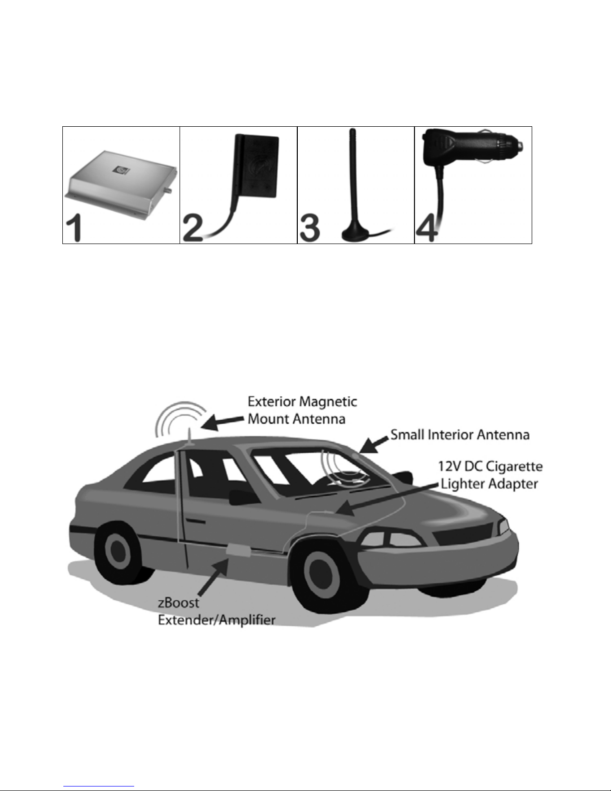
PartsList‐ModelNumber:YX230
ItemDescriptionQuantity
1zBoostIn‐VehicleAmplifierUnit 1
2SmallInteriorAntenna1
3ExteriorMagneticMountAntenna 1
412VDCCigaretteLighterAdapter 1
Theabovediagramisoneexampleofarecommendedinstallation.Other
variationsarepossible.Consultyourlocalmobileelectronicsinstaller.

©2008Wi‐Ex7
WARNINGS
•TheYX230complieswithFCC/ICregulations.Followallguidelinesandreadthis
informationcompletelybeforebeginningtheinstallationprocedure.Never
operatethesysteminanunintendedapplication.
•AllcellularphonesinthevicinityoftheAmplifiershouldbeturnedoffduring
installation.Onlyafterunitisinstalledshouldcellularphonesbeturnedonand
testedwiththesystem.
•Makesuretoconnecttoa12Vsourcethatlosespowerwhenvehicleisoff,or
makesure12VDCCLAdapterswitchisoff.Batterywilldrainotherwise.
•OnlytheprovidedpowercableistobeusedwiththeWi‐Exsystems.Usingany
otherpowercablewillharmthesystem.TheWi‐Ex’swarrantywillbevoidedifany
otherpowercableisused.
•OnlytheantennasprovidedwiththeWi‐Exsystemmaybeused.Useofanyother
antennacouldadverselyimpacttheperformanceofthesystem,causedamageto
theunitandwouldvoidthewarranty.
•ChangesormodificationsnotexpresslyapprovedbyWi‐Exwillvoidtheuser’s
authoritytooperatetheequipment.
InstallationInstructions
Werecommendthatindividualsnotaccustomedtotheinstallationofmobile
electronicsseektheservicesofaprofessionalinstaller.
Step1.PositionAmplifierUnit‐PositionAmplifierUnitwithininteriorofvehicle
andwithina3‐4ft.reachofa12VDCPort.Choosealocationwhereitrestsflatand
isnotahazardtodriver(i.e.underseat).
Step2.PositionExteriorMagneticMountAntenna‐PositionExteriorMagnetic
MountAntennaontopofvehicle,makingsuremagnetissecuredtometalsurface.
ThenroutecablefromExteriorMagneticMountAntennaandconnecttoAmplifier
Unit.
NOTE:Cordwillrunfromexteriortointeriorofvehicle.Cordisdesignedto
withstandpressurewhenclosedinadoor.
Step3.PositionSmallInteriorAntenna‐PositiontheSmallInteriorAntennawiththe
fewestobstructionsbetweentheantennaandthenormaloperatingpositionofthecell
phone.WhentheAntennaisinthedesiredposition,itshouldbenolessthan8inches
(20cm)fromthenormaloperatingpositionofthecellphone.Next,routetheAntenna
cableandconnecttotheAmplifierUnit.AvoidplacingtheAntennabehindanymetallic
objects(ie.mirrorinsunvisor).Donotattachtoanymetalsurface.
IMPORTANT:Foroptimalperformance,donotaffixInteriorAntennatowindshield.

©2008Wi‐Ex8
Step4.AttachDCPowerCable‐Attachsmallendofthe12VDCPowerCableto
theAmplifierUnit.Inserttheremainingendof12VDCPowerCableintoa12V
(cigarettelighter)Portwithinvehicle.
NOTE:Toavoiddrainingbattery,whentheignitionisoff,checkthatAmplifieris
notreceivingpowerwithvehicleturnedoff.TheAmplifier’sLEDshouldbeoff
whenthevehicleisoff.ToturnoffAmplifier,depresstheswitchon12VDCCL
Adapter.
Step5.ExamineLEDlightonAmplifier‐TheLEDlightontheAmplifierUnitindicates
theunitispoweredandtheunit’soperatingstatus.Attempttoachievetheoptimal
signalenhancementwhenpositioningbothAntennasbeforemakingtheAntenna
placementpermanent.Oncepowered,theAmplifierLEDshouldbeGreen.Besurethat
allcellphonesinthevicinityoftheAmplifierareturnedoffduringinstallation.Attach
bothAntennasandpositionthemtoachieveaGreenLED.
GreenLED–Optimalsignalenhancement
RedLED–Poorsignalenhancement
IfyouarereceivingaRedLEDevenaftertryingdifferentAntennapositions,trypowering
theunitoffandonagain.IftheAntennasareconnectedandtooclosetoeachother
whentheAmplifierUnitisturnedon,itwillbeimpossibletoachieveaGreenLED.
Step6.AchieveOptimalEnhancement‐OnceyourLEDisGreen,youmaypermanently
affixboththeMagneticMountandSmallAntenna.IfLEDisRed,adjustthepositionof
theMagneticMountAntennaorSmallInteriorAntennauntiltheLEDisGreen.
Step7.QuickSystemCheck‐PutyourcellphoneantennadirectlynexttotheSmall
Antenna.Seehowmanysignalstrengthbarsyouhave.Next,turnthesystemoff
(eitherturnvehicleofforpresson/offswitch).Youshouldnoticeadecreaseinsignal
barstrength.Theexceptionisifyouareinanareawhere,withthesystemoff,your
phoneisatfullsignalstrength.Pleasenotewhenyouturnthesystemon,ifyourphone
isreceivingmaximumsignalstrengthyouwillnotseeadifference.Inorderforthis
quicktesttowork,youwillneedtotestunitinalessthanmaximumsignalstrength
area.

©2008Wi‐Ex9
5.TECHNICALSUPPORT
LocatetheWi‐ExCarExtenderserialnumberonthebottomoftheAmplifierUnitbefore
calling.Theserialnumbermustbeavailabletoauthorizetechnicalsupportand/or
establishareturnauthorization.Forinstallationtechnicalsupport,contactyourdealer.
Forsystemwarrantyissues,contactWi‐ExSupportbetweenthehoursof8:30AMand
5:30PMEST,Mon‐Fri,at1‐800‐871‐1612orvisitourtechnicalsupportwebsiteat
http://www.wi‐ex.com.TheWi‐ExCarExtendersystemmustbeusedwithWi‐Ex
authorizedequipment.ThetechnicalsupportteamwillonlysupportWi‐Exauthorized
equipment.Contactyourdealerforquestions.
6.TROUBLESHOOTING
IgetaRedLEDontheAmplifier–
IfyouarereceivingaRedLEDevenaftertryingdifferentAntennapositions,turnthe
poweroffandonagain.IftheAntennasareconnectedandtooclosetoeachother
whentheAmplifieristurnedon,itwillbeimpossibletoachieveaGreenLED.
IftheLEDisnotlighted
MakesurethereispowerbeingsuppliedtotheUnit.Ensurethe12VDCCLAdapter
switchisintheONposition.
i.CheckandseethattheRedLEDontheAmplifierisON.
Ifnot,thereisnopowerattheplug.
ii.DisconnectthepowerattheUnitandreconnect.FliptheON/OFFswitchonthe
12VDCCLAdapter.
iii.MakesuretheconnectorisproperlyconnectedtotheAmplifierUnit.
Istillcan’tmakeorreceiveacallonmycellphone.I’mnotgettinganysignal–
AcellularsignalisstillrequiredoutsidethevehiclefortheAmplifierUnittowork.
Thiscannotgenerateacellularsignalwhennoneexists.Thiscanonlyamplifyan
existingsignal.
Idroppedacall–
Therearemanyfactorswhichcanaffectcellularcalls,forexample,ifthecellularsignal
becomessoweakthatitcannotbeamplified,thecallwillbedropped.
TheLEDstaysonevenafterIturnthecaroff–
Whenusingavehicle’s12VPort,somevehiclesmaystillprovidepowerwiththeignition
off.Inthiscase,the12VDCCLAdapter’sSwitchmustbeintheOFFpositionortaken
outofthe12VPorttopreventthecarbatteryfrombeingdrained.

©2008Wi‐Ex10
IgetaGreenLED,butthesignalonmycellphonedoesnotincrease–
First,waiting10‐20secondsisrequiredbeforesomephonesshowanincreaseinthe
signalstrength.Second,makesuretheSmallInteriorAntennaisfacingtheuserandis
within2‐4feet.MakesuretheAntennasareconnectedtotheAmplifierUnit.
Ineedatechnicalsupportspecialist–
Call1‐800‐871‐1612toreachoneofourhighlytrained,technicalexperts.
Ineedtoreturntheunit–
Call1‐800‐871‐1612torequestaReturnAuthorizationnumber.Acustomerservice
representativewillprovideyouwithreturnshipmentinstructions.AReturn
MerchandiseAuthorization(RMA)numbermustbeprovidedbeforereturningthe
product.
©2008Wi‐Ex11
Wi‐Ex
1MecaWay
Norcross,GA30093
USA
1‐800‐871‐1612
www.wi‐ex.com
support@wi‐ex.com
Table of contents


