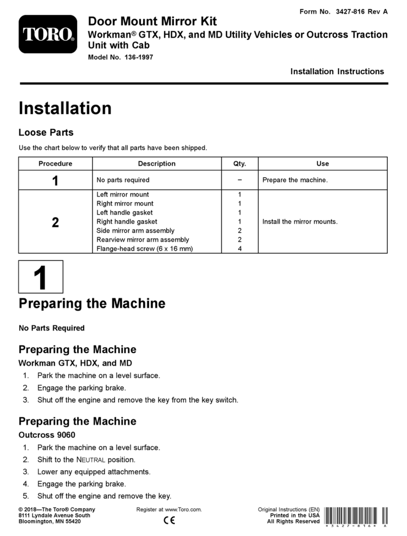
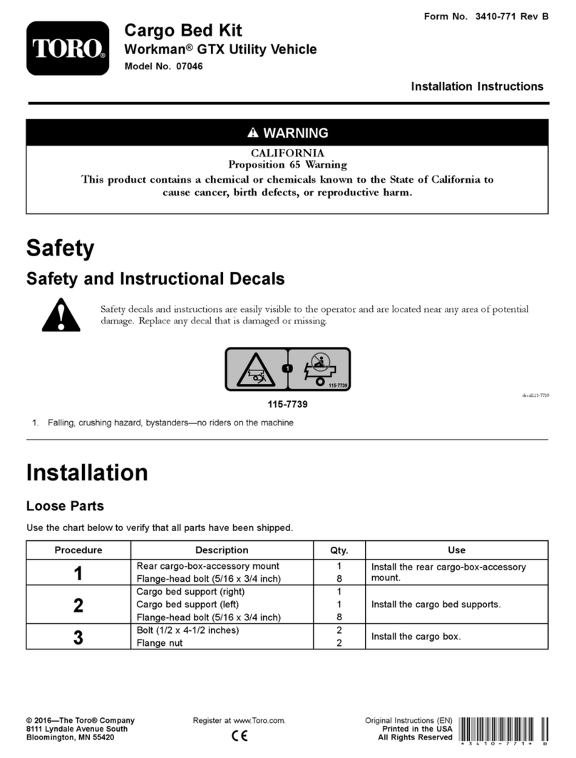
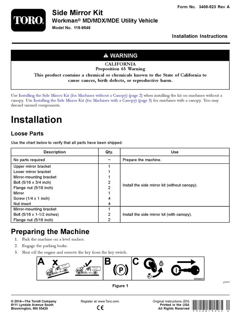
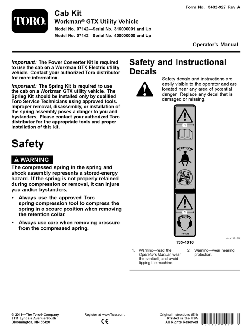
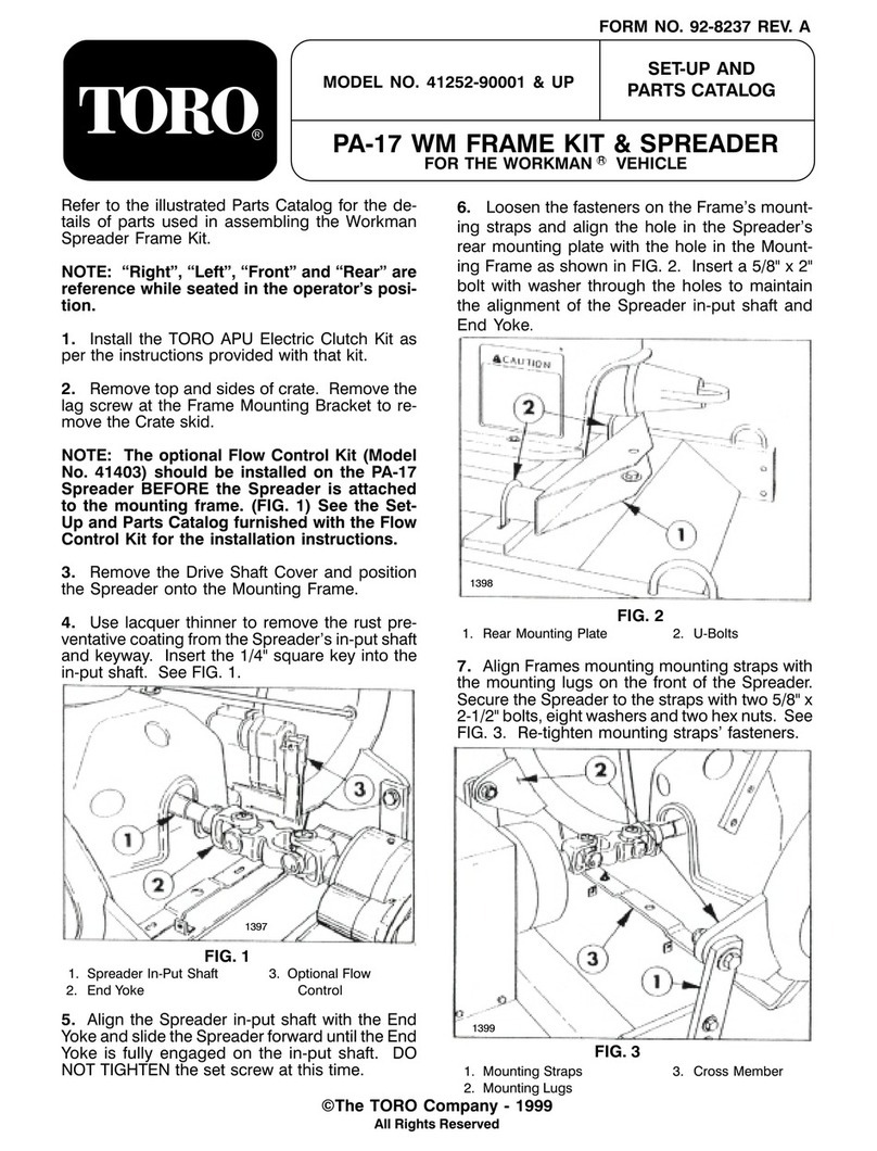
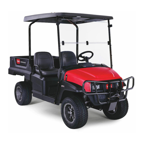
Toro 07337 User manual

Vinyl Enclosure #07337
FOR
Toro Workman MD series only
PARTS LIST – ASSEMBLY INSTRUCTIONS
IMPORTANT
READ THIS MANUAL CAREFULLY AND KEEP FOR FUTURE REFERENCE
CAUTION !
REMOVE THE VINYL PANELS FOR TRANSPORT IN AN OPEN TRUCK OR TRAILER
WARNING !
THIS CAB WILL NOT PROTECT OPERATOR FROM INJURIES CAUSED BY COLLISION, OR OTHER
ACCIDENTS
60276109 1
Form No. 3365-747 Rev A

WARNING
1. This cab is designed to provide foul weather protection only. It does not provide protection
from noise, exhaust fumes, chemicals or injury from collision, or other accidents.
2. Do not operate the machine in confined areas without proper ventilation.
3. Thoroughly check area of operation before using the machine.
MAINTENANCE INSTRUCTIONS
Periodically check all bolts to see that they are tight. If bolts become loose, failure of cab parts may occur.
DO NOT CLEAN THE CLEAR PLASTIC WINDOWS WHEN THE PLASTIC IS DRY.
THE CLEAR PLASTIC WILL SCRATCH.
Avoid contact with plastic windows. Keep plastic windows clean by washing them with clear running water
and rubbing with your bare hands, only. The use of a rag, sponge or brush will scratch the plastic. Liquid
soap may also be used for window cleaning. During freezing weather, an automotive windshield washer
solvent may be used.
Use liquid soap and water to clean colored vinyl portions. Scrubbing with a brush or rag is also permitted
on the colored vinyl portions
STORAGE INSTRUCTIONS
Prior to storage clean the windows and colored vinyl parts with a mild automotive detergent, rinse with
clean water and allow to thoroughly dry, Store cab in a clean dry place out of direct sunlight. Avoid folding
plastic windows.
INSTALLATION
READ THIS MANUAL COMPLETELY BEFORE BEGINNING INSTALLATION.
• The right side of the machine is determined from the operator position.
• Do not tighten bolts during assembly unless instructed to do so.
• Park machine on level ground, set parking brake, remove start key.
• The words "bolt" will refer to a 1/4”x 5/8” bolt and "lock nut"’ will refer to a 1/4” lock nut unless
specified otherwise.
• Some of the steps will require two persons to complete.
2

CARTON CONTENTS #07337 Vinyl Enclosure for Workman MD series
Key # Part # QTY Description
1 60046 1 Rear Post, RH (tagged)
2 60047 1 Rear Post, LH
3 60277 1 Front Post, RH (tagged)
4 60278 1 Front Post, LH
5 60048 1 Top Frame, RH (tagged)
6 60049 1 Top Frame, LH
7 60050 1 Door Post, RH (tagged)
8 60055 1 Top Cross Bar, (has tapped holes)
9 60051 1 Door Post, LH
10 60054 1 Rear Cross Bar
11 60057 1 Windshield
12 60056 4 Top Vinyl Support
13 60061 1 Rear Bow
14 60307 1 Dash Support Bracket, RH
15 60306B 1 Top & Rear Curtain
16 60279B 1 Door, RH
17 60280 1 Door Bottom, RH (tagged)
18 60281B 1 Door, LH
19 60282 1 Door Bottom, LH
20 60283B 1 Front Panel Vinyl
9882 2 Door Latch
9510 1 Hand Wiper Kit, (Installation instructions included)
60285 1 Velcro®Package, (25’ adhesive hook & four alcohol pads)
60074 24” 3/8” Vent Hose
60067 1 90º Fitting for Vent Hose
60063 128” Rubber Door Seal
60284 1 Hardware Package, (Contents listed below)
786 24 1/4”-20 X 5/8” Cap Screw
908 4 1/4”-20 X 1 1/2” Cap Screw
6654 4 1/4”-20 X 1 3/4” Cap Screw
6653 4 1/4”-20 X 2” Cap Screw
730 20 1/4”-20 Lock Nut
3951 8 1/4” Flat Washer
2 8 1/4” Lock Washer
785 2 5/16”-18 X 1” Cap Screw
9294 2 5/16”-18 X 3/4” Carriage Bolt
9842 3 5/16”-18 Flange Lock Nut
317 2 5/16” Flat Washer
906 6 3/8”-16 X 1”Cap Screw
9720 6 3/8”-16 Flange Lock Nut
60308 1 5/16”-18 Clip Nut
45057 4 Door Hinge (slotted)
3

13
8
6
12
5
9
7
10
11
2
1
4
3
Step 1:
Identify the frame parts using the parts list and the above illustration.
4

Step 2; See Figure 2A, 2B, 2C & 2D: Figure 2A
Install fuel tank vent hose.
A. Remove the knob from the gearshift. Remove the
four screws that hold the shifter plate to the shifter
bracket. Remove the four screws that hold the shifter
plate to the seat base. Remove the shifter plate.
B. Remove the cotter pins and clevis pins that secure
the parking cables to the rear wheel brake levers.
Remove the R clamps and C clips holding the brake
cable to the frame.
C. Remove the seats from the seat base. Remove the
8 flange screws securing the seat base to the floor plate
and front frame. Remove the seat base. Figure 2B
D. Install the fuel tank vent extension fitting and hose
as shown below.
NOTE: Installation of this enclosure on
any MDE electric unit and 2010 & up
gasoline models does not require Step 2.
WARNING !
The following procedure to vent the fuel
tank is required to prevent the build up of
gasoline fumes inside the cab. Gasoline
fumes can ignite causing serious injury or
death.
Figure 2D
E. Reverse steps 2 A B & C to replace the seat and
seat base Figure 2C
5

Step 3; See Figure 3A & 3B:
Install right and left Rear Posts (1 & 2).
A. Use three 3/8” x 1” bolts and 3/8” flange
locknuts to fasten the right Rear Post to the
machine as shown.
B. Repeat this step on the left side with the left
Rear Post.
Figure 3A
1
2
C. Tighten the bolts to R.O.P.S. torque
s
p
ecifications.
IMPORTANT !
If a ROPS bar is in place remove the bolts from
the ROPS bar and attach the rear posts on top
of the ROPS bar using the 3/8” x 1” bolts and
3/8” flange nuts.
Figure 3B
Step 4; See Figure 4:
A
Install the Dash Support Bracket (14).
A. Install clip on nut over the bolt hole at
Reference A on the Dash Support Bracket.
Dash Support
Bracket (14)
B. Remove the bolt from the hole at Reference A.
Remove the existing dash bracket and replace it
with the one furnished in this cab.
C. Replace the bolts except for Reference A. Do
not tighten the bolts at this time.
Figure 4
6

Step 5; See Figure 5:
Install the right and left Front Post (3 & 4)
A. Place the right Front Post into position as
shown.
B. Insert a 5/16” x 1” bolt with flat washer inwards
through the slotted tab at Reference B, the dash
and then the Dash Support Bracket into the clip
nut. Do not tighten at this time.
C. Insert a 5/16” x 3/4” bolt down through the tab
welded to the bottom of the post and the
floorboard. Add a 5/16” flange lock nut. Do not
tighten at this time.
D. Repeat the above steps on the other side. use a
5/16” locknut on the bolt at Reference B.
Figure 5
Step 6; See Figure 6:
Install the left and right Top Frames (5 & 6).
A. Place the ends of the top frames into the ends
of the front and rear posts.
B
5
IMPORTANT !
The two thru-holes near the bend of the part
should be at the rear of the top frame and
the single tapped hole must be to the inside
of the frame.
3
Figure 6
7

Step 7; See Figure 7:
Install Door Post right and left (7 & 9), Top Cross
Bar (8) and Rear Bow (13).
13
8
9
A. Hold the upper left Door Post in place over the
two holes at the top. Insert two 1/4” x 2” bolts
inwards through the holes. Repeat this step on the
right side.
B. Place the Top Cross Bar (tapped holes up)
over the bolts protruding through the Top Frame.
C. Place the Rear Bow over the rear bolt. Add
lock nuts. Do not tighten at this time.
D. Repeat steps 7 B & C on the right side.
Figure 7
Step 8; See Figure 8:
Install Rear Cross Bar (10) and secure the lower
end of the Door Post.
A. Insert two 1/4” x 1 3/4” bolts inwards through
the lower end of the Door Post, the Rear Post and
then one end of the Rear Cross Bar. Add lock
nuts. Do not tighten at this time.
10
B. Repeat the above step on the right side.
9
Figure 8
8

Step 9; See Figure 9:
Figure 9
Install Windshield (11)
A. Set the Windshield in place between the Front
Posts and Top Frames. Place a 1/4” lock washer
over each of four 1/4” x 1 1/2” bolts. Align the
holes in the parts and insert the bolts into the
tapped holes. Do not tighten at this time.
11
Step 10; See Figure 10:
Figure 10
12
Install Top Vinyl Supports (12)
A. Place the vinyl supports in place as shown.
Insert eight bolts down through the holes in the
Supports, the Top Cross Bar and the Windshield.
Do not tighten the bolts at this time.
9

Step 11; See Figure 11A, 11B, & 11C:
Install right and left Doors (16 & 18), right and left
Door Bottoms (17 & 19), Door Hinges, and Door
Latches,
Hinges
A. Bolt two door Hinges to the Door Post using
1/4” x 5/8” bolts and 1/4” lock washers to attach
hinges to the out side of the Door Post. Tighten the
bolts in the center of the hinge slots.
B. Insert the top of the hinge rod into the top hinge.
Lower the door down into the bottom hinge. Place
a Door Latch into the cut out as shown. Make slits
in the vinyl for the bolts. Use four bolts & nuts with
flat washers on the slots to fasten Door Latch to the
Door. Do not tighten at this time.
C. Use two bolts (heads against the vinyl) and nuts
to attach the Door Bottom to the Door. Open the
Velcro®flaps and close them around the rod.
Secure the ties to the bar on the door.
Figure 11A
19
Figure 11C
Figure 11B (Inside of open left Door)
10

Step 12; See Figure 12A, 12B & 12C:
Install Rubber Door Seal. Cab frame / Door
alignment.
Figure 12A
IMPORTANT !
The ‘U’ shaped section of the rubber door
seal will be applied to the edge of the door.
The ‘tube’ shaped section of the rubber
door seal should be between the doorframe
and the cab fram
e.
The use of a rubber mallet is recommended
to gently seat the seal onto the doorframe.
A. Cut two 63” pieces of rubber door seal.
Allowing about a free inch to tuck behind the top
panel’s over lap, start pressing the ‘U’ shaped
section of the rubber door seal onto the edge of the
door frame. Follow the doorframe across the top
edge and down along the leading edge of the
doorframe. There will be some excess past the
doorframe.
B. Cut out the section of “tube” between the
arrows to prevent the Latches from binding.
Repeat the above steps on the other side. Figure 12B
C. Place an 8” piece of adhesive Velcro®in place
as shown to attach the door flap on left side.
D. Close the Doors and latch them. Adjust the
latches and hinges as needed to align the Doors.
E. Tighten all of the cab frame bolts left
loose in previous steps. Remove the Doors
by lifting them up and out of the bottom
hin
g
es.
IMPORTANT !
Clean the area where the adhesive hook
Velcro®is to be applied. Remove all dirt and
oil then wipe with the alcohol pads
provided.
8
”
Velcro
®
Figure 12C
11

Step 13; See Figure 13:
Install adhesive hook Velcro®for Front Panel Vinyl.
A. Cut a strip of adhesive hook Velcro® 45” long
and apply to the lower front edge of the Windshield
as indicated by the arrows.
B. Cut two strips of adhesive hook Velcro® 17” long
and apply to the forward side of the Front Post as
indicated by the arrows.
Figure 13
Step 14; See Figure 14A & 14B:
Install adhesive hook Velcro®.
A. Cut a strip of adhesive hook Velcro® 36” long
and 7” long. Apply to the upper front edge of the
Windshield as indicated by the arrows.
B. Cut two strips of adhesive hook Velcro® 30” long
and apply to the forward sides of the Rear Posts as
indicated by the arrows.
Figure 14B
45
”
17
”
30” Velcro
®
Strips Front side
of rear posts
Velcro
®
Strips
36” 7”
Rear
Bow
Figure 14A
30” Velcro
®
starts here
12

Step 15; See Figure 15:
Install adhesive hook Velcro®.
A. Cut two strips of adhesive hook Velcro® 17” long
and 3” long and apply to the bottom side of both
Top Frames as indicated by the arrows.
NOTE: Start the strip about 1 1/2” from the
mountin
g
flan
g
es of the Door
p
osts.
Step 16; See Figure 16:
Install adhesive hook Velcro®.
A. Cut two 10” pieces of adhesive hook Velcro®
and apply one piece to the outside of each rear
post. Start the piece just below the lower edge of
the Rear Cross Bar mounting flange.
Figure 15
Velcro
®
Strips
17” 3”
10” Velcro
®
Strip
Figure 16
13

IMPORTANT !
Before continuing to STEP 17, check the position of the rear bow with Figure 14B and adjust
accordingly.
Step 17:
Install Top / Rear Curtain
A. Cut a 40” piece of adhesive hook Velcro®(DO NOT remove protective backing strip) Press the
hooked strip onto the loop (soft pile) Velcro®located at the bottom edge of the Rear Curtain section of the
panel. (window)
B. Starting from the front, attach the front edge Velcro®to the two strips previously installed on the
windshield frame in steps 14A.
C. Drape the Top & Rear Curtain over the top frame members and down the back (between the ROPS
bar if installed) of the installed frame. DO NOT fasten any other Velcro®strips at this time.
D. Fasten the Velcro®strips of the Top panel to the strips installed on the top frame in step 15, see figure
15.
E. Fasten the Velcro®strips of the Top panel (rear window section) to the strips installed on the Rear
Posts in Step 14 and Step 16.
F. Carefully remove the protective strip (avoid separating the strips) from the adhesive hook Velcro®that
was installed on the lower edge of the Rear Curtain (step 17A)
G. Gently pull down on the curtain and press the adhesive hook Velcro®evenly to the back of the seat
base.
Step 18; See Figure 18A &18B:
Install Front Panel Vinyl (20) & the assembled
Doors.
A. Attach the Velcro®strips at the top together.
Attach the sides to the Velcro®strips on the
forward side of the Front Posts.
B. Reinstall Doors and secure the Rear flap of
the Door to the Rear Curtain Velcro®. Secure the
flaps on the rear corners of the top to the Door
Velcro® at the arrow.
Figure 18B
Figure 18A
20
14
Other Toro Automobile Accessories manuals
Popular Automobile Accessories manuals by other brands

Cradlepoint
Cradlepoint COR IBR600 installation guide
Rola
Rola PMX188 Fitting instructions
Nav TV
Nav TV PCM3CAM Install manual
Mitsubishi
Mitsubishi MZ360135EX Installation and handling instructions

aFe Power
aFe Power 77-46309 instruction manual
Mitsubishi MOTORS
Mitsubishi MOTORS MZ313817 installation instructions

ULTIMATE SPEED
ULTIMATE SPEED CLIX I manual
WeatherTech
WeatherTech No-Drill MudFlap installation instructions
stellar labs
stellar labs Surf Skis manual

Bosch
Bosch QUICK FIT F026C00470 installation instructions
Cruz
Cruz Evo Rack E23-140 Assembly instructions
FVC
FVC Low Pro Roof Rack 148 HR installation guide
