Inventure Automotive G2 User manual

Reefer Interface G2
based on
FMS Gateway G2™

User’s Manual
Inventure
FMS Gateway G2™–
Reefer interface

User’s Manual FMS Gateway G2 –
© Inventure Automotive Electronics R&D, Plc.
Legal Notice
Information furnished in this publication is believed to be accurate and reliable. However,
Inventure assumes no responsibility for the consequences of use. Information contained in this
publication regarding the device applications and the like is intended through suggestion only.
Product specifications are subject to change or modification without notice.
This document is for use by the intended recipient and contains confidential information under
applicable law. You are hereby formally notified that any use, copying or distribution of the
document, in whole or in part, is strictly prohibited.
This publication supersedes and replaces all information previously supplied.
Trademarks
The Inventure logo and product names are trademarks of Inventure, Inc. and are protected by
copyright law.
All rights reserved.
Copyright Notice
© Copyright 2020, Inventure, Inc.
Revision
D01-018-09-04-08-03EN
Contact
INVENTURE Automotive Electronics R&D, Plc.
11 Tarcali Strret
H-1113 Budapest
HUNGARY
Phone: +36 1 381-0970
E-mail: support@inventure-automotive.com
URL: www.inventure-automotive.com

User’s Manual FMS Gateway G2 –
© Inventure Automotive Electronics R&D, Plc.
Table of contents
1INTRODUCTION .............................................................................................................5
2THE FMS GATEWAY G2 REEFER INTERFACE............................................................5
2.1 MAIN FEATURES........................................................................................................5
2.2 ADDITIONAL FEATURES..............................................................................................5
2.3 HOW TO USE INVENTURE FMS GATEWAY G2 REEFER INTERFACE ...............................6
3SAFETY NOTICES..........................................................................................................7
4PACKAGE CONTENTS ..................................................................................................8
5CONNECTION OVERVIEW.............................................................................................9
5.1 V_CAN 1CONNECTOR............................................................................................10
5.2 MAIN CONNECTOR .................................................................................................10
5.3 USB MINI CONNECTOR ...........................................................................................11
6INSTALLATION TO VEHICLE ......................................................................................12
7TROUBLESHOOTING, LED STATUS ..........................................................................13
7.1 PROPER OPERATION ...............................................................................................13
7.2 V_CAN 1ERROR ...................................................................................................14
7.3 V_CAN 1IDLE........................................................................................................14
7.4 DIAG IDLE .............................................................................................................14
7.5 UNKNOWN VEHICLE.................................................................................................14
7.6 V_CAN 2ERROR ...................................................................................................14
7.7 FMS CAN OUTPUT ERROR .....................................................................................14
7.8 BOOTLOADER STATE (USB CONNECTED) .................................................................15
8INVENTURE SUPPORT INFORMATION ......................................................................15
9SYSTEM CHARACTERISTICS .....................................................................................16
10 WARRANTY..................................................................................................................17
11 HOW TO CONTACT INVENTURE? ..............................................................................18
12 LIST OF FIGURES ........................................................................................................19
13 LIST OF TABLES..........................................................................................................19

User’s Manual FMS Gateway G2 –
© Inventure Automotive Electronics R&D, Plc.
1 Introduction
Thank you for purchasing an Inventure product. Your new FMS Gateway G2™interface is a
carefully engineered, high quality durable product with intelligent features and robust styling.
It is designed to give you the quality and convenience you expect from an automotive
measuring instrument.
To familiarize yourself with all the features of your unit please read the following instructions
carefully. Retain this guide for future reference.
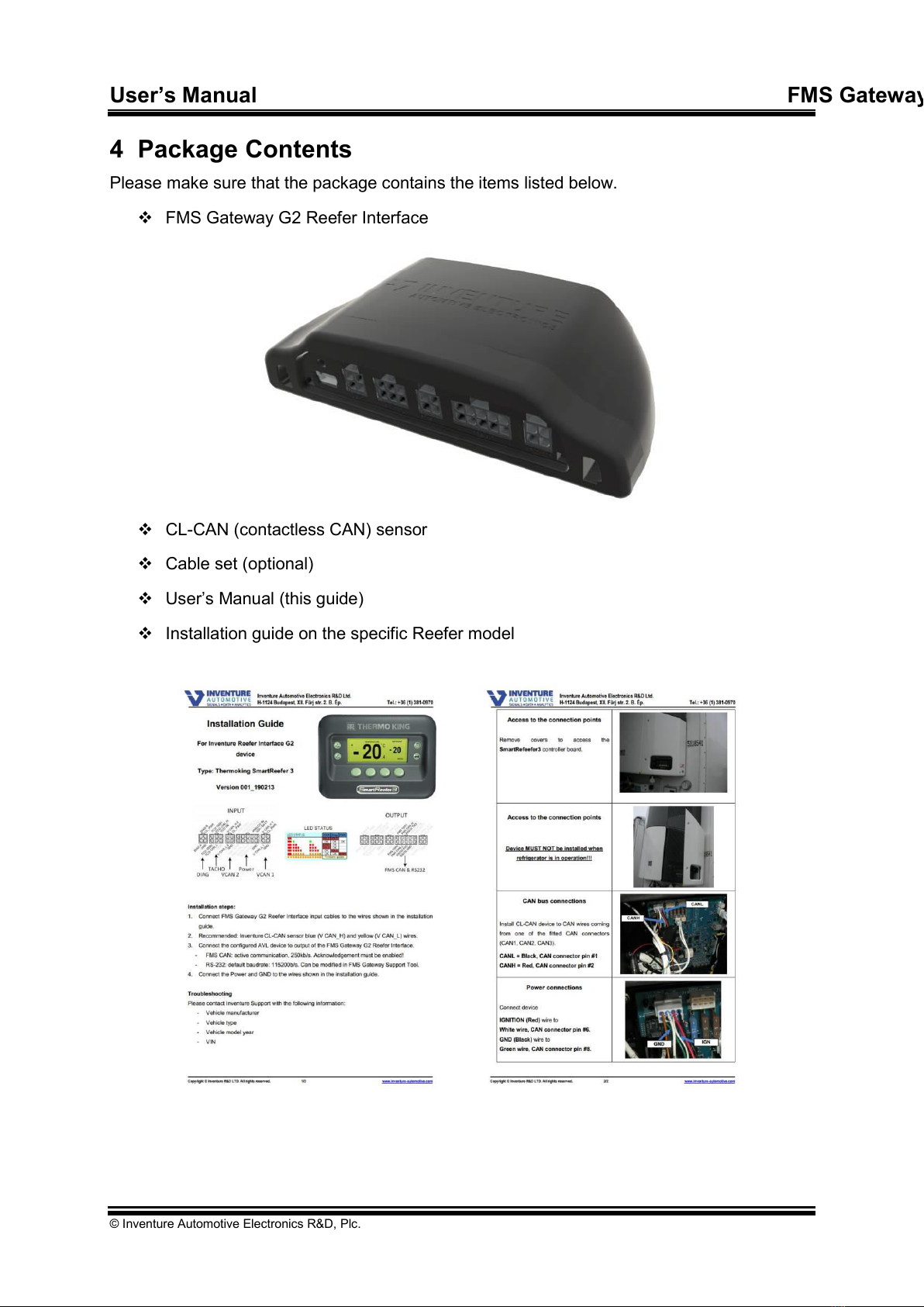
2 The FMS Gateway G2 Reefer Interface
The interface connects to Thermo King Smart Reefer controller electronic communication
channel, acquires and transfers real time sensor data on its output. The output format can be
compliance with standard FMS CAN, and/or RS232. The output data can be transferred via
hardwire (FMS Gateway output cable –FMS CAN and/or RS232) method.
The FMS Gateway G2™ basically has only one firmware for each manufacturing group
and it uses Automatic Vehicle Detection which means that after installing the device will
detect your vehicle by itself. To use the standard FMS Gateway G2 as Reefer Interface you
need to use the General Truck firmware and upload it by using the proper Device Database
(the method is detailed in this document)
2.1 Main features
This intelligent interface provides contactless and safety solution for Thermo King
refrigerators with comprehensive measurement as listed below:
High-Speed CAN and/or RS232 output
Multiple zone temperature up to three separated zones1
No need for OEM translator interface
FMS compatible (CAN output compliance with FMS CAN bus)
Easy integration with any telematics systems
The Reefer Interface solution can be used as extra feature2on reefer equipped rigid trucks to
acquire vehicle related FMS data and reefer related data with one device at once.
2.2 Additional features
The FMS Gateway G2 interface has advantageous features that are accessible via mini USB
connector, such as:
Vehicle measurement: If the vehicle is not supported, then you can easily make a
CAN measurement using FMS Gateway G2. You just send this measurement to
Inventure Support (support@inventure.hu), we analyze the files and update new
firmware as soon as possible
1if the Thermo King unit is able to handle multiple zones
2Extra feature: please contact Inventure Automotive for details

User’s Manual FMS Gateway G2 –
© Inventure Automotive Electronics R&D, Plc.
Troubleshooting: should you need further assistance during installation,
measurements can be recorded from the Support Tool PC software. The
measurement can be analyzed by Inventure experts and effective support can be
provided.
Explanation:
Firmware Update
oAn option to update the firmware of the device so it is usable in other vehicles
2.3 How to use Inventure FMS Gateway G2 Reefer Interface
Identify your Reefer controller module
oSupported Thermo King units:
All Thermo King units equipped with SR2 controller
All Thermo King units equipped with SR3 controller
Firmware update process (skip if you ordered with updated firmware)
oInstall FMS Gateway Support Tool PC Software
See further details in the FMS Gateway Support Tool User’s manual
oAcquire and refresh the Device Database in FMS Gateway Support Tool
oUpdate the latest Truck firmware via FMS Gateway Support Tool
oEnable the related output messages in G2 Configuration menu via FMS
Gateway Support Tool
On site installation process
oDuring installation please refer to the Reefer specific Installation guide. Please
contact Inventure Support (support@inventure.hu) for the install guide.
E.g.: ThermoKing_SR3_Reefer_IF_G2_Installation_Guide_v01.pdf
oInstall the CL-CAN sensor according to the guide, connect its cable to the
V_CAN 1 slot.
oConnect the power supply wires of the Main cable to the proper points
oAfter device installation, please connect input cables (Power, Ground, Vehicle
CAN input and other inputs when needed). See Section 5 for more details.
oConnect the FMS Gateway G2 output to the input of your AVL device.
After successful installation and power-up, the device testing can be started.
oThe FMS Gateway G2 has an in-built Status LED that indicates its operating
status. If everything works as it should, the LED flashes green once in every 5
seconds. If not, please check Section 7 for further information.

User’s Manual FMS Gateway G2 –
© Inventure Automotive Electronics R&D, Plc.
oThe complete Reefer tracking system can be tested online by visiting your
fleet tracking system’s website, where you are able to see the Reefer data
beside the GPS position.
3 Safety notices
Please read the following safety instructions carefully. Inventure Automotive
accepts no liability for damage that results from disregarding the safety
instructions.
Usage of the interface is permitted for industrial purposes only.
The interface must not be used in situations in which human lives depend upon
the operation of this equipment.
Product must be installed by professional and this fact should be recorded legally
The interface may be damaged by contact with water or any liquids. Use and
store the interface in an area protected from water
Do not expose the interface to direct sunlight or high temperature (see section 11
for reference) to ensure proper operation

User’s Manual FMS Gateway G2 –
© Inventure Automotive Electronics R&D, Plc.
4 Package Contents
Please make sure that the package contains the items listed below.
FMS Gateway G2 Reefer Interface
CL-CAN (contactless CAN) sensor
Cable set (optional)
User’s Manual (this guide)
Installation guide on the specific Reefer model

User’s Manual FMS Gateway G2 –
© Inventure Automotive Electronics R&D, Plc.
5 Connection overview
INPUT DESCRIPTION
CONNECTOR
Vehicle CAN 1 channel –Default input for Reefer
V_CAN 1
Vehicle CAN 2 channel 3
V_CAN 2
Diagnostics channel 4
DIAG
Tachograph connection 5
TACHO
Main harness (Power, FMS CAN, RS232, Analog)
MAIN
Programming / Configuring / Measuring channel
mini USB B
Table 1: Input description
Figure 1: Device connectors
For the device proper functioning, please make sure to connect only to the following points
according to the charts. The rest should be left as is (DNC - Do Not Connect).
3Not used for Reefer Interface
4Not used for Reefer Interface
5Not used for Reefer Interface

User’s Manual FMS Gateway G2 –
© Inventure Automotive Electronics R&D, Plc.
5.1 V_CAN 1 connector
4 3
12
V CAN_H1
CL_PWR
V CAN_L 1
GND
Figure 2: Micro Fit 4-pin (V_CAN 1) assignment
Pin Nr.
Designation
Description
1
GND
Ground
2
V CAN_L 1
Vehicle CAN 1 bus CAN Low line
3
CL_PWR
Power output for CL-CAN sensor
4
V CAN_H 1
Vehicle CAN 1 bus CAN High line
Table 2: Micro Fit 4-pin (V_CAN 1) assignment
5.2 MAIN connector
89
10 67
12345
FMS TER1
FMS TER2
FMSCAN_L
RS232 RXD
FMS CAN_H
RS232 GND
RS232 TXD
ANALOG IN
IGN /BATT
Figure 3: Micro Fit 10-pin (MAIN) assignment
Pin Nr.
Designation
Description
1
GND
Ground
2
RS232 GND
RS232 Ground
3
RS232 RXD
RS232 channel receive data line
4
FMS CAN_L
FMS CAN bus CAN Low line
5
FMS TER 2
FMS CAN bus terminating resistor activation loop 2
6
IGN / BATT
Ignition / Battery + input
7
ANALOG IN
Analog sensor input (e.g.: fuel level sensor)
8
RS232 TXD
RS232 channel transmit data line
9
FMS CAN_H
FMS CAN bus CAN High line
10
FMS TER 1
FMS CAN bus terminating resistor activation loop 1
Table 3: Micro Fit 10-pin (MAIN) assignment

User’s Manual FMS Gateway G2 –
© Inventure Automotive Electronics R&D, Plc.
5.3 USB Mini connector
Please make sure to follow the below steps:
Connect FMS Gateway to computer (use Mini USB –USB cable)
Figure 4: USB Mini B to USB A cable
Install device driver
Install FMS Gateway Support Tool software
Activate FMS Gateway Support Tool software using license file (Send the activation
request file in e-mail to Inventure Automotive support)

User’s Manual FMS Gateway G2 –
© Inventure Automotive Electronics R&D, Plc.
6 Installation to vehicle
In order to avoid damaging the vehicle or the device the installation must be performed by
professional, skilled person.
During installation please consider safety instructions (see Section 3) and follow the
instructions below:
1. Make sure that the FMS Gateway G2 Reefer Interface device has the latest firmware
installed, and it is appropriately configure for the Reefer model (check firmware version
and configuration by using FMS Gateway Support Tool)
2. Update the appropriate firmware and configuration to the device if necessary (by using
FMS Gateway Support Tool)
3. Update the settings if you need specific configuration (by using FMS Gateway Support
Tool)
4. Connect the vehicle communication bus wires to the interface input connectors by using
vehicle specific Installation guide
oConnect CL-CAN sensor to V_CAN 1
5. Connect device output to the telematics device
oFMS CAN and/or
oRS232
6. Turn vehicle ignition ON, and check FMS Gateway device LED status. LED should be
flashing green once in every 5 seconds. Should it be different, please see
Troubleshooting on Section 9.
7. Check telematics device’s operating status (LED indicator if available) then verify the
dataflow from vehicle on remote server database.

User’s Manual FMS Gateway G2 –
© Inventure Automotive Electronics R&D, Plc.
7 Troubleshooting, LED status
The FMS Gateway has a status LED on the face of the enclosure which indicates the current
operational mode.
When ignition turns ON the status LED lights RED for 5s (initialization process), after this the
status LED indicates the current operation state. The status LED flashes 1-5 times in 5s
period with different color, see attached table.
Status LED flashing states:
State
Status LED
Flashing / 5s
Proper operation
Green
1
No communication on device input
Not flashing
0
V_CAN 1 input Error
Red
2
V_CAN 1 input Idle
Red
3
DIAG input Idle
Red
4
Unknown Vehicle
Red
6
V_CAN 2 input Error
Red
7
V_CAN 2 input Idle
Red
8
K-Line input Idle
Red
9
FMS CAN output Error
Yellow
5
Bootloader state (USB Connected)
Yellow
rapid
Table 4: Device working status
LED STATUS: CAN Diag FMS
IDLE
OK
ERR
OK IDLE
ERR
OK OK
OK OK
OK
OK
IDLE IDLE
Firmware update
Figure 5: Status LED flashing
7.1 Proper operation
Device works correctly, LED flashes GREEN 1 time in 5s period.
In this working state the device gets power supply (voltage and current OK) and detects the
input CAN and/or DIAG communication channels’messages.
In this operating state the device and the GPS device connection are correct, the GPS
device sends CAN acknowledges (in case of FMS CAN connection).

User’s Manual FMS Gateway G2 –
© Inventure Automotive Electronics R&D, Plc.
7.2 V_CAN 1 Error
In case of the status LED flashes RED 2 times in 5s period the FMS Gateway detects error
on V_CAN 1 input channel. The device detects CAN errors on vehicle CAN communication
bus.
Possible Faults:
FMS Gateway Firmware does not fit for this vehicle model
oCheck the updated firmware version, use FMS Gateway Support Tool to read
firmware version. Update firmware if necessary.
V_CAN 1 bus connection wrong:
oCheck V_CAN 1 connections (CAN Low ~2,3V, CAN High 2,7V DC)
V_CAN 1 bus lines reverse connection:
oCheck V_CAN 1 connections reverse polarity (CAN Low ~2,3V, CAN High
2,7V DC)
7.3 V_CAN 1 Idle
This state is not relevant on Reefer Interface.
7.4 DIAG Idle
This state is not relevant on Reefer Interface.
7.5 Unknown vehicle
This state is not relevant on Reefer Interface.
7.6 V_CAN 2 Error
This state is not relevant on Reefer Interface.
7.7 FMS CAN Output Error
In case of the status LED flashes YELLOW 5 times in 5s period the connection between the
FMS Gateway device and the GPS device is not working properly. Check connections!
Possible Faults:
FMS CAN bus connection is wrong:
oCheck FMS CAN connections (CAN Low ~2,3V, CAN High 2,7V DC)
FMS CAN bus lines have reverse connection:
oCheck FMS CAN connections for reverse polarity (CAN Low ~2,3V, CAN High
2,7V DC)
No CAN acknowledge from GPS device:
oIf there is no acknowledge on FMS CAN bus then FMS Gateway cannot
transfer CAN messages to GPS device.

User’s Manual FMS Gateway G2 –
© Inventure Automotive Electronics R&D, Plc.
oSet GPS device CAN settings Normal or turn on CAN acknowledge.
No CAN terminating resistor:
oCheck 120Ohm terminating resistors on CAN bus according ISO11898-2
standard.
FMS CAN bus baudrate is wrong:
oThe FMS CAN output baudrate is 250kb/s according to FMS Standard. Set
this baudrate in GPS device settings.
7.8 Bootloader state (USB Connected)
In case of the status LED flashes YELLOW rapidly the FMS Gateway is in firmware update
mode. In this mode you can easily update the firmware of the FMS gateway device, change
device settings and make measurement from the vehicle's input communication channels.
Possible Faults:
USB cable is connected:
oIf USB cable is connected to the device the FMS Gateway is in firmware
update mode. Disconnect USB Cable from the device.
8 Inventure Support information
In case of any problem with device installation, firmware upgrade or any questions please
contact Inventure Automotive support team (support@inventure-automotive.com). To get the
fastest answer please describe the problem as detailed as possible.
Please provide the following information in case of any problem:
Vehicle Type, model year, VIN, Engine code
Short description of the problem
Company name
Device serial number
LED status (which color and how often it flashes)
Firmware name
If you can connect to the device, the whole device information screen content (use
FMS Gateway Support Tool)
oBootloader version
oLast update was successful or not
oUpdate trial counter
oLast update trial date
oFirmware description

User’s Manual FMS Gateway G2 –
© Inventure Automotive Electronics R&D, Plc.
FMS Gateway Support Tool Error message
9 System Characteristics
Parameter
Symbol
Min.
Tip.
Max.
Unit
Power Supply
Voltage supply
VIGN
8
32
V
Operating current (12V)
I_op
50
70
mA
Operating current (24V)
I_op
30
50
mA
Operating current (Sleep)
I_op
3
4
mA
Environmental characteristics
Storage temperature
-40
85
ºC
Operating temperature
-20
75
ºC
Humidity
0
70
%
FMS CAN output interface
Baud rate
250
Kbaud
FMS CAN terminating resistor
120
Ohm
CAN mode
Normal
CAN 2.0B ID
29
bit
Box parameters
Length
110
mm
Width
50
mm
Height
30
mm
Mass
75
g
Table 5: System characteristics

User’s Manual FMS Gateway G2 –
© Inventure Automotive Electronics R&D, Plc.
10 Warranty
There is a one-year warranty on FMS GATEWAY G2™starting from the date of the original
purchase. The warranty covers any defect in materials or workmanship. The warranty is valid
only if FMS GATEWAY G2™ was operated under normal circumstances in regular use. The
warranty does not include damage from misuse or neglect.
As FMS GATEWAY G2™ has a well thought design, it is thoroughly tested before release
and it is composed of high quality parts, there should be no need for maintenance of any
parts of FMS GATEWAY G2™ during normal operation. If the box was damaged the
warranty for FMS GATEWAY G2™ is no longer valid.
Remember to save your sales receipt in case of you ever need warranty service. Please
refer to the serial number of your FMS GATEWAY G2™ in case of any problems. The serial
number can be found on a label outside the box. In case of warranty claims contact your
local dealer or directly Inventure, Inc.

User’s Manual FMS Gateway G2 –
© Inventure Automotive Electronics R&D, Plc.
11 How to contact Inventure?
Inventure provides customer support via its World Wide Web (WWW) site. The Inventure
website is available by using from your favorite Internet browser at:
www.inventure-automotive.com
Our website provides a variety of services. Read up-to-date information about the company,
the products, application possibilities and the services. Frequently asked questions and the
corresponding answers are also available on the Inventure site.
If you have problems, questions, suggestions, or you just want to express your opinion about
us or our products, please feel free to write an email to us, and we will surely find a way to
the solution.
support@inventure-automotive.com
Come and visit our website, tell us your experience concerning our product, fill out the
registration form to be able to inform you directly about the latest results of research and
development and the continuously improving customer services.
Your comments are also welcome under the following address:
Inventure Automotive Electronics R&D, Inc.
H-1124 Budapest
Fürj Street 2.
HUNGARY
Phone: (+36) 1 381-0970

User’s Manual FMS Gateway G2 –
© Inventure Automotive Electronics R&D, Plc.
12 List of figures
Figure 1: Device connectors .................................................................................................. 9
Figure 2: Micro Fit 4-pin (V_CAN 1) assignment...................................................................10
Figure 3: Micro Fit 10-pin (MAIN) assignment ......................................................................10
Figure 4: USB Mini B to USB A cable ...................................................................................11
Figure 5: Status LED flashing ...............................................................................................13
13 List of Tables
Table 1: Input description ...................................................................................................... 9
Table 2: Micro Fit 4-pin (V_CAN 1) assignment....................................................................10
Table 3: Micro Fit 10-pin (MAIN) assignment........................................................................10
Table 5: Device working status.............................................................................................13
Table 6: System characteristics............................................................................................16
Other manuals for G2
1
Table of contents
Other Inventure Automotive Automobile Accessories manuals
Popular Automobile Accessories manuals by other brands

Thule
Thule AeroBlade 7601 instructions

BPW
BPW AirSave Operating and installation instructions

Scosche
Scosche POWERUP 400 manual

Webasto
Webasto Thermo Pro 50 Eco installation instructions

Havis-Shields
Havis-Shields Side Slide-Out Step 1997-2007 Chevrolet Full Size Van... installation instructions

Mongoose
Mongoose MDVR-M Series Quick start up guide