WELDMATIC
205s
MANUAL
Page
3
SAFEN
Before this equipment
is
put into operation. the SAFEPRACTICES section at the
back of the manual must be read completely
.
This will help to avoid possible injury
due
to
misuseor improperwelding applications
.
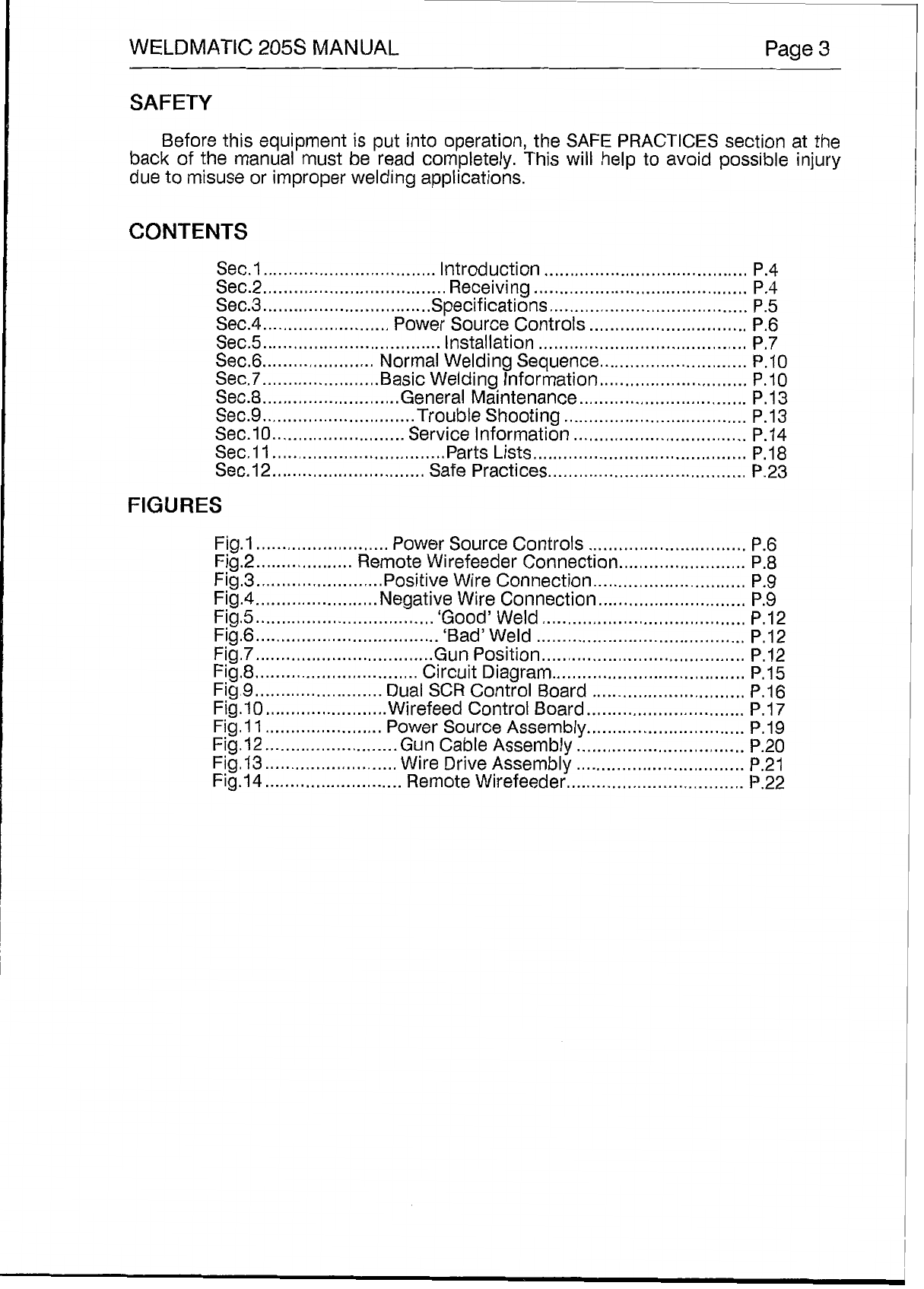
CONTENTS
Sec.1 Introduction
........................................
P.4
Sec.2
....................................
Receiving
..........................................
P.4
Sec.3
.................................
Specifications
.......................................
P.5
Sec.4
.........................
Power SourceControls
...............................
P.6
Sec5
...................................
Installation
.........................................
P.7
Sec.6
......................
NormalWeldingSequence
.............................
P.10
Sec.7
.......................
BasicWelding Information
.............................
P.10
..................................
Sec.8
...........................
General Maintenance
.................................
P
.
13
Sec.9
..............................
Trouble Shooting
....................................
P.13
Sec.10
..........................
Service Information
..................................
P
.
14
Sec
.
11
................................
..PartsLists
..........................................
P
.
18
Sec.12
..............................
Safe Practices
.......................................
P.23
FIGURES
Fig.1
..........................
Power SourceControls
...............................
P.6
Fig.2
...................
Remote WirefeederConnection
.........................
P.8
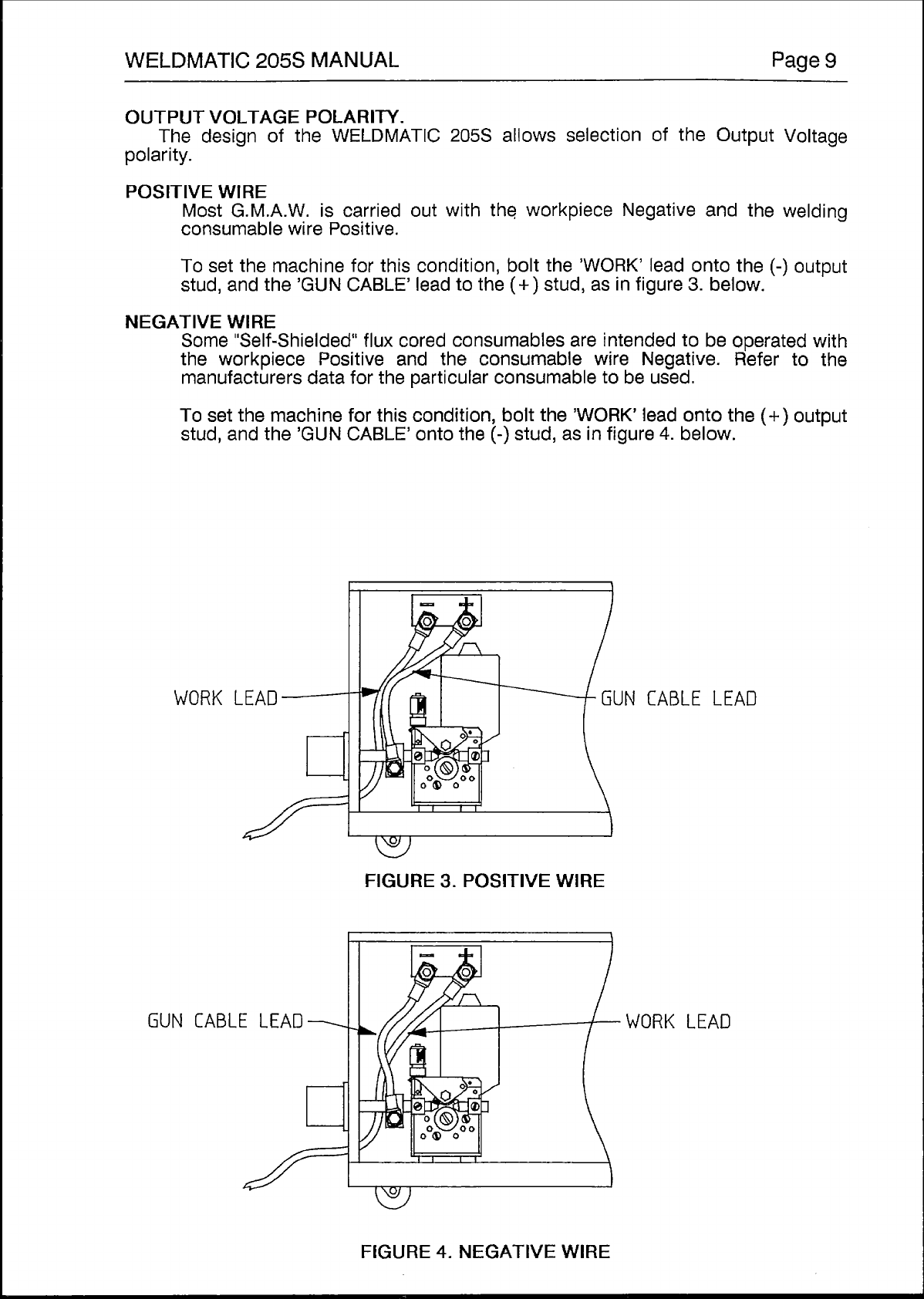
Fig.3
.........................
PositiveWire Connection
..............................
P.9
Fig.6
....................................
‘Bad’Weld
.........................................
P.12
Fig.7
...................................
Gun Position
........................................
P.12
Fig.8
................................
Circuit Diagram
......................................
P.15
Fig.9
.........................
Dual
SCR
ControlBoard
..............................
P
.
16
Fig.l2
..........................
GunCableAssembly
.................................
P.20
Fig.13
..........................
Wire DriveAssembly
.................................
P.21
Fig.14
...........................
Remote Wirefeeder
...................................
P.22
Fig.4
........................
Negative WireConnection
.............................
P.9
Fig.5
...................................
‘Good’
Weld
........................................
P.12
Fig.10
........................
WirefeedControl Board
...............................
P.17
Fig
.
1
1
.......................
Power Source
Assembly
...............................
P.19