manuals.online logo
Brands
  1. Home
  2. •
  3. Brands
  4. •
  5. WIA
  6. •
  7. Welding System
  8. •
  9. WIA CP27-9 User manual

WIA CP27-9 User manual

This manual suits for next models

3

Other WIA Welding System manuals

WIA Weldmatic Weldarc 145i User manual

WIA

WIA Weldmatic Weldarc 145i User manual

WIA MC100-0 User manual

WIA

WIA MC100-0 User manual

WIA Weldmatic 205S User manual

WIA

WIA Weldmatic 205S User manual

WIA WELDARC 135 User manual

WIA

WIA WELDARC 135 User manual

WIA VORTEX AD15VRADl5-0 User manual

WIA

WIA VORTEX AD15VRADl5-0 User manual

WIA CP149-1 User manual

WIA

WIA CP149-1 User manual

WIA Weldmatic 200i MIG User manual

WIA

WIA Weldmatic 200i MIG User manual

WIA WELDMATIC Weldarc 140i User manual

WIA

WIA WELDMATIC Weldarc 140i User manual

WIA Weldmatic 200i User manual

WIA

WIA Weldmatic 200i User manual

WIA Weldmatic 190 User manual

WIA

WIA Weldmatic 190 User manual

WIA Weldmatic 270 CP132-2 User manual

WIA

WIA Weldmatic 270 CP132-2 User manual

WIA Weldmatic Fabricator P135-2 User manual

WIA

WIA Weldmatic Fabricator P135-2 User manual

WIA WIREFEEDER W67 User manual

WIA

WIA WIREFEEDER W67 User manual

WIA Weldmatic 396 User manual

WIA

WIA Weldmatic 396 User manual

WIA MC115-0 User manual

WIA

WIA MC115-0 User manual

WIA WELDMATIC 356 User manual

WIA

WIA WELDMATIC 356 User manual

WIA weldmatic 350i CP139-2 User manual

WIA

WIA weldmatic 350i CP139-2 User manual

WIA CP117-2 User manual

WIA

WIA CP117-2 User manual

WIA Weldmatic 396 User manual

WIA

WIA Weldmatic 396 User manual

WIA WELDARC 200AC/DC User manual

WIA

WIA WELDARC 200AC/DC User manual

WIA WELDMATIC 270 User manual

WIA

WIA WELDMATIC 270 User manual

WIA WELDARC 400 User manual

WIA

WIA WELDARC 400 User manual

WIA WELDARC 200DC User manual

WIA

WIA WELDARC 200DC User manual

WIA WELDMATIC 270C User manual

WIA

WIA WELDMATIC 270C User manual

Popular Welding System manuals by other brands

Razorweld RAZORCUT45 instruction manual

Razorweld

Razorweld RAZORCUT45 instruction manual

Lincoln Electric Fleet 500 Operator's manual

Lincoln Electric

Lincoln Electric Fleet 500 Operator's manual

Migatronic OMEGA 220 quick guide

Migatronic

Migatronic OMEGA 220 quick guide

Magmaweld ID 300T DC user manual

Magmaweld

Magmaweld ID 300T DC user manual

Sealey POWERMIG Series instructions

Sealey

Sealey POWERMIG Series instructions

Defort 98291254 user manual

Defort

Defort 98291254 user manual

Hobart Welding Products AirForce 375 owner's manual

Hobart Welding Products

Hobart Welding Products AirForce 375 owner's manual

GF MSA 330 instruction manual

GF

GF MSA 330 instruction manual

Hakko Electronics FX-888D instruction manual

Hakko Electronics

Hakko Electronics FX-888D instruction manual

Abicor Binzel ABIPLAS WELD 100 W operating instructions

Abicor Binzel

Abicor Binzel ABIPLAS WELD 100 W operating instructions

EWM Taurus 355 Basic TDM operating instructions

EWM

EWM Taurus 355 Basic TDM operating instructions

Thermal Dynamics PakMaster 100 XL plus operating manual

Thermal Dynamics

Thermal Dynamics PakMaster 100 XL plus operating manual

Berner PLASMACUT 54 instruction manual

Berner

Berner PLASMACUT 54 instruction manual

Pro Spot PR-155 Assembly instructions

Pro Spot

Pro Spot PR-155 Assembly instructions

Forney 210 operating manual

Forney

Forney 210 operating manual

Thermal Arc 400S operating manual

Thermal Arc

Thermal Arc 400S operating manual

Lincoln Electric HANDYMIG 170I Operator's manual

Lincoln Electric

Lincoln Electric HANDYMIG 170I Operator's manual

GYS PROTIG 201 AC/DC Original instructions

GYS

GYS PROTIG 201 AC/DC Original instructions

manuals.online logo
manuals.online logoBrands
  • About & Mission
  • Contact us
  • Privacy Policy
  • Terms and Conditions

Copyright 2025 Manuals.Online. All Rights Reserved.

WELDING INDUSTRIES
OF
AUSTRALIA
A
BlVlSlQN
OF
WELDING
INDUSTRIES
LTD
ACN
004
547
Ill
Head
Office
and
International
Sales
5
Allan
Street,
Melrose
Park
South
Australia,
5039
Telephone
(08)
8276
6494
Facsimile
(08)
82766327
OWNERS MANUAL
WELDMATIC
305
MODEL
NO.
CP27-9, REV. C
MODEL
NO.
CP27-IO, REV.
C
07195
QUALITY WELDINGPRODUCTS, SYSTEMSAND SERVICE
4::
YLLV
Paae
2
WELDMATIC
305
MANUAL
WELDMATIC
305
MANUAL
Page
3
SAFETY
Beforethis equipment
is
put into operation. theSafe Practicessectionat the back
of
the manualmust be read completely
.
Thiswill help to avoid possibleinjury due to
misuseor improper welding applications
.
CONTENTS
Sec.1 Introduction
........................................
P.4
Sec.2
....................................
Receiving
..........................................
P.4
Sec.3
.................................
Specifications
.......................................
P.5
Sec.4
.........................
Power SourceControls
...............................
P.6
Sec5
...................................
Installation
.........................................
P.7
Sec.7
.......................
BasicWelding Information
.............................
P.ll
..................................
Sec.6
......................
NormalWelding Sequence
.............................
P.11
Sec.8
...........................
GeneralMaintenance
.................................
P.14
Sec9
..............................
Trouble Shooting
....................................
P.14
Sec.10
..........................
Service Information
..................................
P.15
Sec.11
..................................
PartsLists
..........................................
P.18
Sec.12
..............................
Safe Practices
.......................................
P.24
FIGURES
Fig.1
..........................
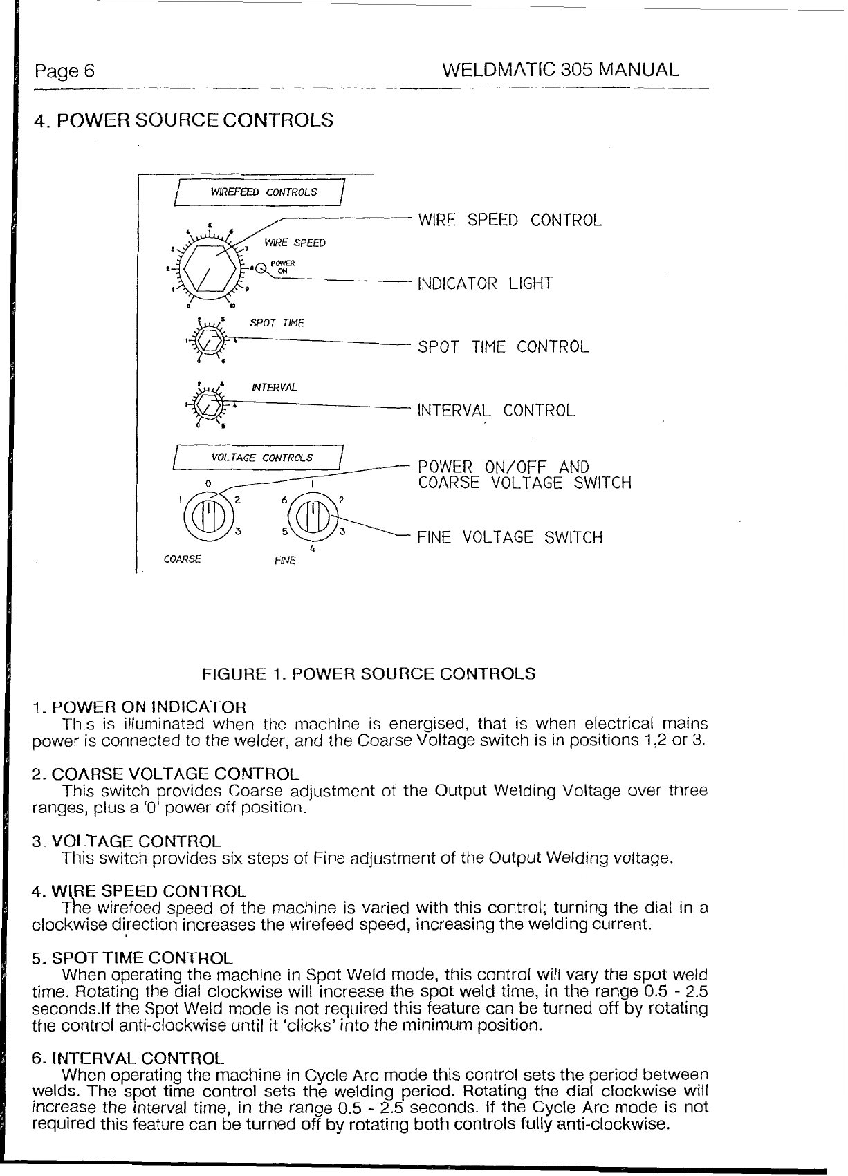
Power Source Controls
...............................
P.6
Fig.2
......................
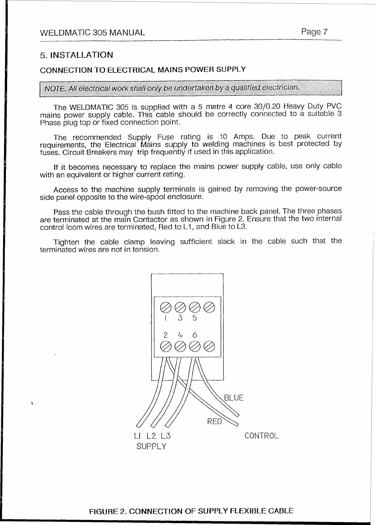
Connection ofSupplyCable
...........................
P.7
Fig.3
...................
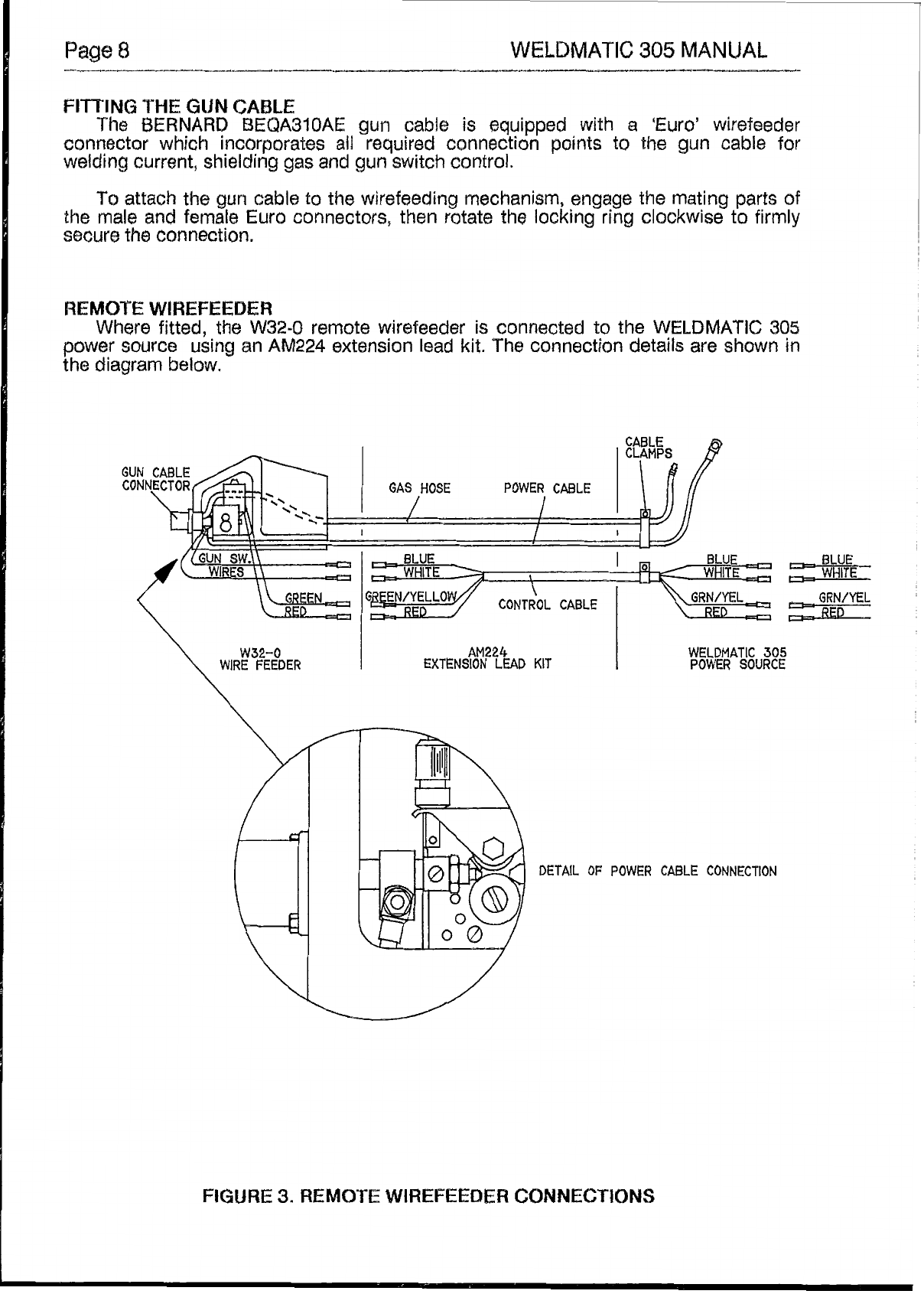
RemoteWirefeeder Connection
.........................
P.9
Fig.4
.........................
PositiveWire Connection
..............................
P.10
Fig.6
...................................
"Good"Weld
........................................
P
.
13
Fig.7
....................................
"Bad"
Weld
.........................................
P.13
Fig.8
...................................
Gun Position
........................................
P.13
Fig.9
................................
Circuit Diagram
......................................
P.16
Fig.10
........................
Wirefeed Control Board
...............................
P.17
Fig.13
..........................
Gun
CableAssembly
.................................
P.21
Fig.14
..........................
Wire DriveAssembly
.................................
P.22
Fig.15
...........................
Remote
Wirefeeder
...................................
P.23
Fig5
........................
NegativeWire Connection
.............................
P.10
Fig.1
1
.......................
Power Source Assembly
...............................
P
.
19
Fig.12
..........
Power Source Ass'y (RemoteWirefeeder)
.................
P.20
Page
LC
WELDMATIC
305
MANUAL
_I_.
''
""
The information contained in this manual is setout to
enable
you
to properly
maintainyour new equipment and ensurethat you obtain maximum operating efficiency,
Please
ensure that
this
information
is
kept
in
a
safe
place
for
ready
reference when
requiredat anyfuture time.
When requesting spareparts,pleasequotethe model
and
serialnumber of the
machine
and
part number
of
the item required.
All
relevant numbers are
shown
in lists
contained in this manual.Failure to supply this information
may
result
in
unnecessary
delays
in
supplying
the correct parts.
Gas
Metal Arc Welding
(G.M.A,W.)
is
B
basically
simple
weldingprocess,where
a
consumable
wire
is
fed
by
motor
driven drive roilers
to
a
welding gun, and where
welding current is supplied from the welding power
SQUTCB.
The
weldin arcisstruck
between
the
workpiece and the
end
of
the
wtre,
which melts inta the
we1
t
pool.
The arc
and the
weld
pool
are both shielded by
gas
flew
from the
gun,
or
in
the
case
of"self
shielded"
wires, by
gases
generated
by
the wire core.
Theprocess is veryversatile in that
by
selection
sf
the correct wire composition,
diameter and shielding
gas,
it can be used for applications ranging from sheetmetal
to
heavy
plate,
and
metals
ranging from
carban
steel
to
aluminium
alleys.
The
WELDMATIC
305
has
been
designed
to
be
used
with
consumable
wires in
the
range from
O.Gmm
to
-l
.6mm diameter.
The
smaller wire
sizes
are used
when
welding at
iuwercurrents,
such
8s
sheet-metal applications. Increasingthewirediameterpermits
higher weldingcurrentsto
be
selected,
A
common
application
sf
G.M.A.W.
isforwelding
Mild
Steel.
tn
this application,
it
Mild
Steel
solid
consumable
such
as
AUSTMIG
€S4
or
ES6
is
used
with
a
shielding
gas
of
Carbon
Dioxide,
or Argon mixed withCarbon Dioxide.Alternatively,Flux-cored
consurnables
are availablein both
gas
shielded, and
'gasless'
self
shieldingtypes.
Stainless
steel
and
Afuminium
can
be
welded with
G.M.A.W.
using the correct
consumablewire and shietding
gas.
Check
the
e
uipmentreceivedagainstthe shipping invoice
to
makesurathe
shipment
is
cornp
7
ete
and undamaged.
If
any
damage
has occurred in transit, please
immediately notify
yaw
supplier.
The
027-9
(Internal Wirefeeder) Package contains;
1%
WELDMATIC
309
Powersource.
m
BEQA31OAE
BERNARD
Gun
cable,
3
metre, Euroconnector.
m
HA101-185
Regulator and
Flowgauge.
(Argon)
a
(This)
OwnersManual.
The
CP2748
(Remote
Wirefeeder)
Package
contains;
WELDMATIC
305
PowerSource.
B
W32-0
Wirefeeder.
LB~
AM224-0
IO
tnter-connecting
lead
kit,
$6
metre.
U
BEQA3f
d
AE
BERNARO
Gun
cable,
3
metre, Eura connector.
HA181-185
Regulator
and
Flowgauge.(Argon)
I
(This)
Owners
Manual.
WELDMATIC
305
MANUAL
Page
5
3.
SPECIFICATIONS
ManufacturedtoAustralianstandardAS1.966.1-l985
PRIMARY VOLTAGE
................................................380
VoltsA.C., Three Phase,
50
hz.
RATED PRIMARY CURRENT
..................................
I1
Amps
MAX
PRIMARY DEMAND
........................................
19
Amps,
12
kVA (Minimum
requirementfor supply from engine
driven alternator.)
FUSE
RATING
..........................................................
15
Amps
FITTED
SUPPLY
CABLE
..........................................
30/0.20
Four Core,
Heavy Duty PVC
WIRE
SIZE
RANGE
..................................................
0.6mm
-
1.6rnm diameter
OPEN
CIRCUIT VOLTAGE
......................................
18to
40
Volts in
18
steps.
WIRE
SPEED
RANGE
...............................................
to
15
Metres/min
WELDING
CURRENT RANGE
.................................
35
-
305
AMPS
COOLING
.................................................................
Fan cooled, air drawn in
through top louvre.
Dutycycle
280
Amps
@
30
Volts,
30%
Duty cycle
RATED
OUTPUT
......................................................
150
Amps
@
23
Volts,
100%
Duty cycle
is
defined
in
Australian Standard AS1966.1 asthe ratio of arcingtime to
5
minutesinany
5
minute period, expressedas a percentage.
Page
6
WELDMATIC
305
MANUAL
4.
POWER
SOURCE
CONTROLS
t&T-
WIRE
SPEED
CONTROL
WIRE
SPEED
INDICATOR
LIGHT
0
a
‘BL
SPOT
TIME
CONTROL
1
lNTERVAL
CONTROL
I
VOL
TAG&
CONTROLS
I,
POWER ON/OFF AND
0
-1
COARSE
VOLTAGE
SWITCH
‘@:
FINEVOLTAGESWITCH
COARSE
FINE
4
FIGURE
1
-
POWER
SOURCE
CONTROLS
1.
POWER
ON
INDICATOR
This is illuminated when the machtne
is
energised, that
is
when electrical mains
power is connected to
the
welder,
and theCoarse Voltage switch
is
in
positions
1,2
or
3.
2.
COARSE
VOLTAGE
CONTROL
ranges,
plus
a
‘0’
power off position.
This
switch provides
Coarse
adjustment
of
the Output Welding Voltage over three
3.
VOLTAGE CONTROL
This switch providessix steps
of
Fineadjustment of theOutput Welding voltage.
4.
WIRE
SPEED
CONTROL
clockwise direction increasesthewirefeed speed, increasingthewelding current.
5.
SPOT
TIME CONTROL
When operating the machine in Spot Weld mode, this control willvary the spot
weld
time. Rotatingthe dial clockwise will increase the spot weld time,
in
the range
0.5
-
2.5
seconds.lf
the
Spot Weld mode is not requiredthis feature can be turned
off
by
rotating
the controlanti-clackwise until
it
‘clicks’ into theminimum position.
The
wirefeed
speed
of
the
machine
is
varied with this control; turning the dial in a
6.
INTERVAL
CONTROL
When operatingthe machine inCycle
Arc
mode this control sets the periodbetween
welds. The spot time control sets the weldingperiod.Rotating the dialclockwisewill
increase the interval time,
in
the range
0.5
-
2.5
seconds.
if
the Cycle Arc mode is not
requiredthis featurecan be turned off by rotating both controls
fully
anti-clockwise.
WELDMATIC
305
MANUAL
Page
7
5.
INSTALLATION
CONNECTION
TO
ELECTRICAL
MAINS POWER
SUPPLY
The WELDMATIC
305
is
supplied with a
5
metre
4
core
30/0.20
Heavy Duty
PVC
mainspower
supply
cable. Thiscableshouldbe correctly connected to a suitable
3
Phase plugtop or fixed connection point.
Therecommended Supply Fuse rating
is
10
Amps.Due
to
peak current
requirements, the Electrical
Mains
supply
to
welding machines is best protected
by
fuses. Circuit Sreakers may trip frequently
if
used inthis application.
If
it
becomesnecessary to replace the mainspower supply cable, use only cable
Access to the machine supply terminals is gained
by
removing
the
power-source
side panelopposite tothe wire-spool enclosure.
Pass the cable through the bushfitted to themachine back panel. The three
phases
are terminated at the main Contactor
as
shown
in
Figure
2.
Ensurethat the two internal
control
loom
wires areterminated, Red to
L1
,
and Blueto
L3.
with anequivalentor higher current rating.
Tighten the cable clamp leavingsufficient slack in the cable such that the
terminatedwires are
not
intension.
LI
L2
L3
SUPPLY
CONTROL
FIGURE
2.
CONNECTION
OF
SUPPLY
FLEXIBLE
CABLE
Page
8
WELDMATIC
305
MANUAL
_I_
FITTING
THE
GUN
CABLE
The
BERNARD
BEBA3lOAE
gun
eabie
is
equipped with
a
‘Euro’wirefeeder
connector
which
incorporates
all
required
connection paints
to
the
gun
cable
for
welding
current, shielding
gas
and
gun
switch
control.
To
attach the
gun
cable
to
the
wirefeeding mechanism,
engage
the mating parts
sf
the
male
and
female
Euro
connectors, then rotate the locking ring
clockwise
to
firmly
secure
the
connection.
REMQTE WIREFEEDER
Where fitted,
the
W324
remotewirefeederis connected
Is
the
WELDMATIC
305
power
source
using
an
AM224
extension lead kit. The connection details
are
shown
in
the
diagram
below.
BLUE
E
WHITE
GBN/YEL
r”
RED
WELDMATIC
305
POWERSOURCE
DETAIL
OF
POWER
CABLE
CONNECTION
FIGURE
3.
REMOTE
WIREFEEDEW
CONNECTiOMS
WELDMATIC
305
MANUAL
Page
9
FlmlNG
THE
GAS
BOTTLE
Depending on configurationof the cylinderto be used, the gas flowmeter
/
regulator
may be fitted directly to the cylinder,
or
in
conjunction with an elbow fitting.
DO
NOT
apply
any greasetothesejoints, and tighten thenutssecurely.
Fit the end ofthe gas inlet
hose
fromthe
back
panel of the machine tothe
connector suppliedwith theflow regulator, and securewiththe clamp
also
supplied.
FllTlNG
THE
CONSUMABLE
WIRE
The quality of the consumable wire greatlyaffects how reliably a gas metal arc
welder will operate.
For
bestresultswhen welding mildsteel, we recommend quality
WIA
AUSTMIG
ES4
or
ES6.
Dirty, rusty
or
kinkedwire will notfeed smoothly through the gun
cable and will cause erratic welding. Deposits fromthe wire will clog the
gun
cable
liner
requiringit
to
be replaced prematurely.
Placethe spool
of
welding wire onto the
spool
holder. The location
pin
should mate
with a hole provided
on
the wire
spool
body. Fit the-spool retaining
'R'clip
supplied.
Check theadjustment
of
the
spool
brake, which should
be
set to prevent over-run
of
the
wire
spool at theend
of
a weld, without unduly loadingthe wirefeed motor.The
braking can beadjusted by the Nyioc nut
using
a
15/16" AF
or
24mm
socket wrench.
FEEDING
THE
CONSUMABLE
WIRE
Open the
two
roll
drive mechanism
by
lifting
the pressure lever upwards, which lifts
the upper roller away from the driven roller. The end of the welding
wire
can now be
passed through the inlet guide, over the bottom driven roller, and into the output wire
guide tube.
Check that the drive roller
groove
is correctfor the
wire
in
use. Theappropriate size
is stamped on the visible side
of
theinstalled roiler. Check also thatthecorrect size
contact tipis
fitted
at
the
gun end. Refer to section
11
for gun partnumbers.
Return the top roller to the dosed positionand, with the machine turned
on,
close
the
gun
switch to feed wire through the
gun
cable. Adjust the compressionscrew to
provide sufficient clamping of the drive
rolls
drive to achieve constant wirefeed.
Do
not
overtighten.
Page
10
WELDMATIC
305
MANUAL
OUTPUT VOLTAGE
POLARITY.
The
design of the
WELDMATIC
305
allows selection of the outputvoltage polarity
POSITIVE WlRE
Most
G.M.A.W.
is
carriedoutwith the workpiece Negativeand thewelding
consumable wire Positive.
To
set the machine for this condition, bolt the
’WORK’
lead onto the
(-)
output stud, and the
’GUN
CABLE’
lead to the
(+)
stud, as in
figure
4.
below.
NEGATIVE
WIRE
Some ‘self-shielded’flux cored consumables are intended to be operated with
the workpiece Positive andthe consumable wire Negative.Refer to the
manufacturersdatafor the particular consumabie to be used.
To
set the machine forthiscondition,boltthe
’WORK’
lead ontothe
(+)
output stud, and the
’GUN
CABLE’
onto the
(-)
stud, as infigure
5.
below.
WORK
LEAD
0
0
I
U
FIGURE
4.POSITIVE
WIRE
II
\
GUN
CABLE LEAD
WORK
LEAD
LEAD
FIGURE
5.
NEGATIVE WlRE