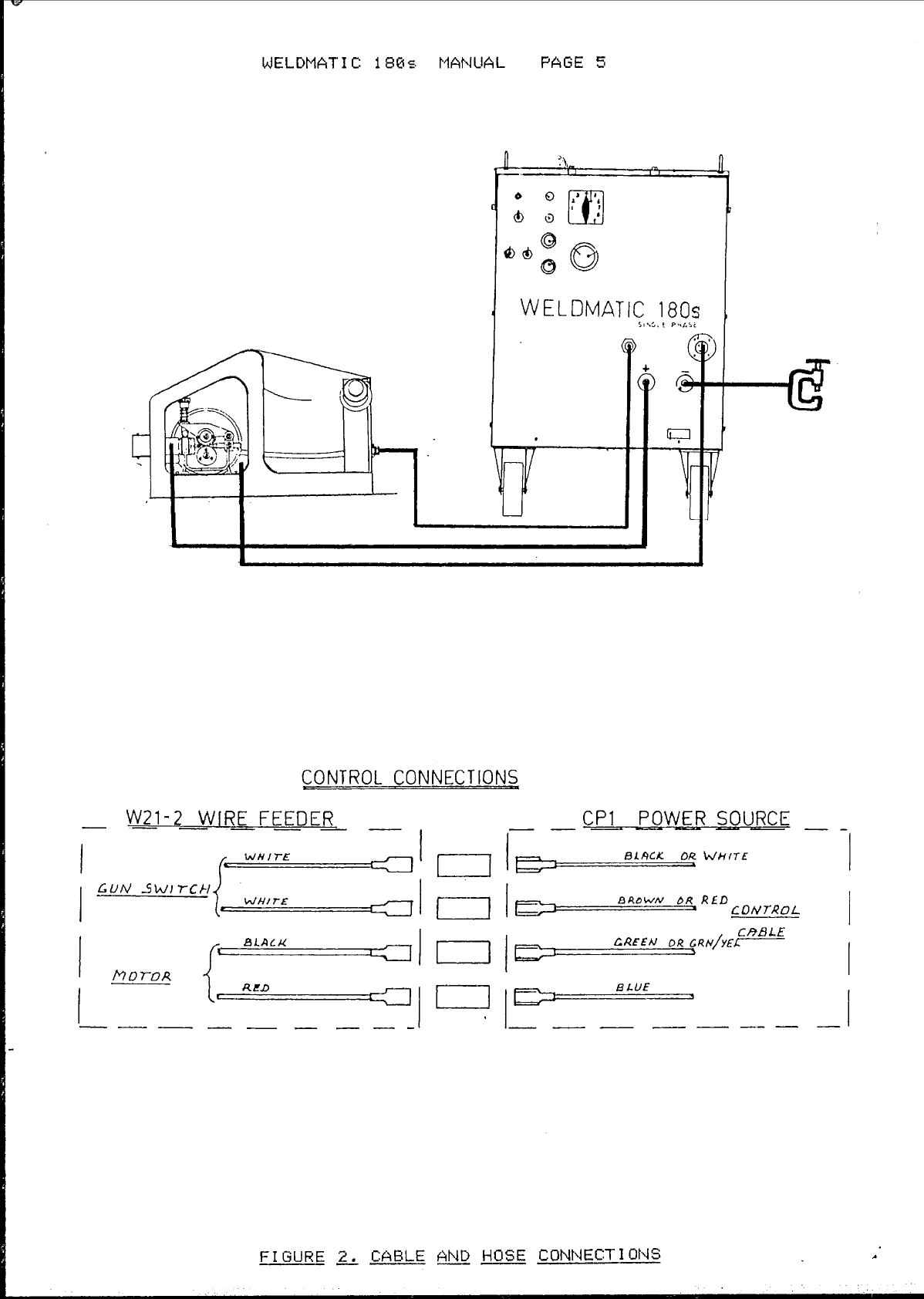
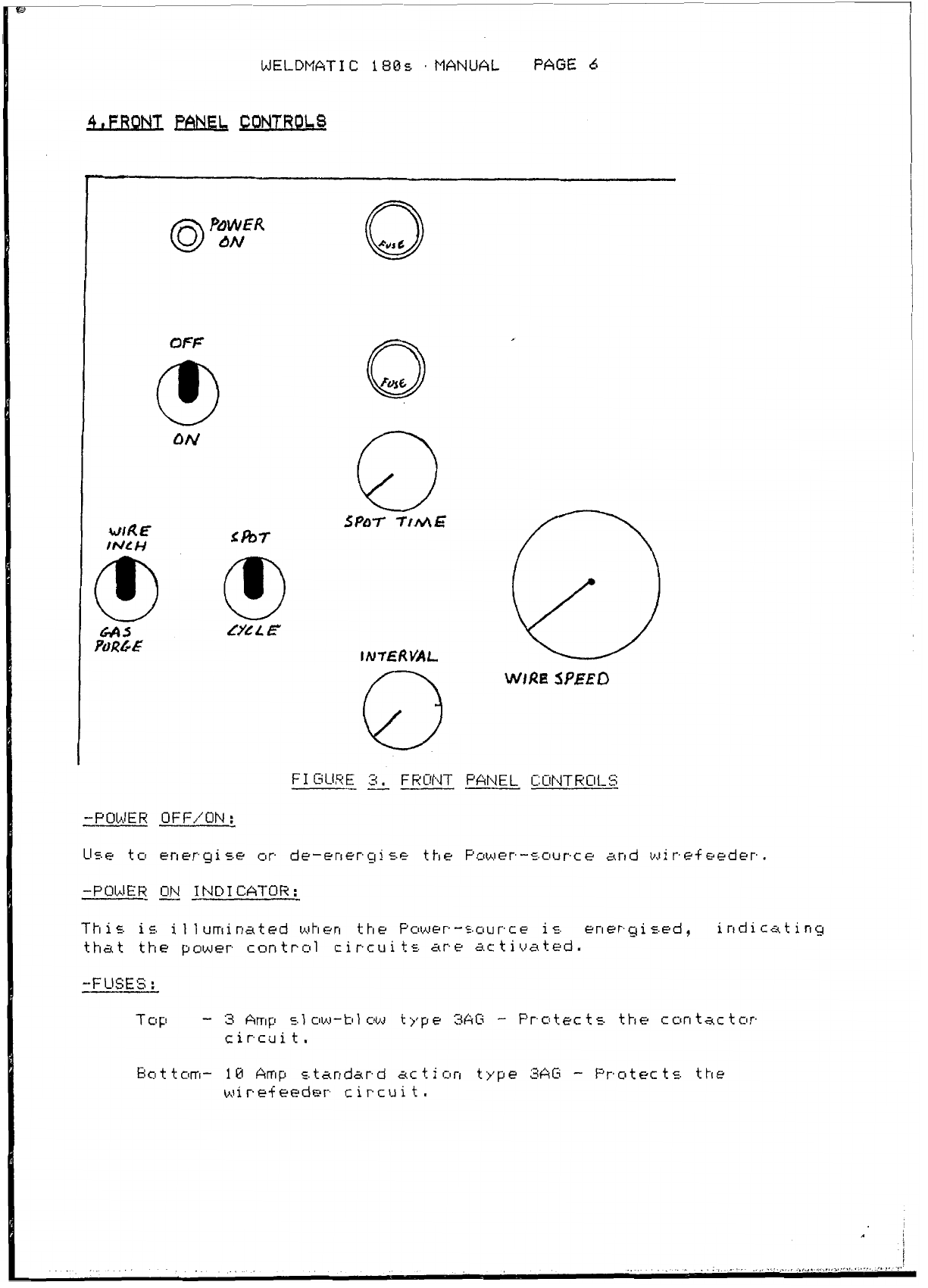
WIA Weldmatic 180s CP17 User manual

MANUFACTURED
BY
WELDINGINDUSTRIES
OF
AUSTRALIA PTY LTD
HEAD OFFICE AND EXPORT DIVISION
2-20
AustarcAuenue5
ThorrIac.town,
ERUIPMEbIT MANUFACTURING DIU1
SION
1
1
2
C)~OJS.
Rclad
,
Edwards
t
own
,
SCIIJ
t
h
SALES RRANC:HES
Meltuurne
83
429
4766AA32493
Sydney
Er2
647
2655
AA24155
Newca5.t
1
e
Er49
61
1668
Bric.bane
87
844
1371
WC11
1
ongung
G142
25'
3447
Vice
3874
ph
83
465
Facsimile
G13
465
Mackay
679
51
Adel
aide
88
352
Pert
h
09
361
Launceston
863
44
251
1
AA32493
861
2
3532
3622
AA82856
7088
AA72936
53822
MELDPIAT
I
C
180
S.
PLEASE Et4SURE THAT THIS FOLDER
I
S
KEPT
IN
A
SAFE
PLACE
FOR
REAlD'Y
REFERENCE WHEN REQUIRED.

CONTENT8
SECT1
ON
1
2
3
4
6
7
8
9
c
J
F1GUHE
1
2
3
4
5
7
E
P
18
11
d
PAGE
l
1
2
6
8
9
18
12
15
PAGE
CONTENTS
SFEC
I
F
I
CAT
I
ON$
RECE
IO1
NG
I
NSTALLAT
I
ON
CONTROLS
WELDINGSET-UP
GENERAL MAINTENANCE
TROUBLE SHClOTING
CONTROL PRINTEDCIRCUIT
BOARDS
SFAREPARTS LISTS
. .
,
,..
.
..
A'

WELDMATIC
188s
MANUAL
PAGE
1
L
SPEC1
F1
CAT1
ONS
1.1
TECHNI
CkL
-
WeldingOutput
48
-
1
88
~ITI~
C.
-
Output
us1
tagE.
21
-
38
VDC
-
Duty
Cycle.
1
E;@
ArrIF'E.,
58%
188
Amps,
35X
-
Over
1
clad
Prcttec
t
i
or1 Recti
f
i
er
Therrrlcts.tats (Thermal
j
-
WireSpeedRange
G1
-
16
metrew'mi n
-
I
n5.u
1
at
i
or1
C:~~E.C.
'H''
-
148
C;
rise
at
48
C
amtlient
-
Encl
osure
Dr
i
p-proo-f
-
1.2
STANDARD
PACKAGE
-
AM132-8/'? Nine
Metre
Accec.c.ory
Lead
Kit
-
AM132-0/15
Fifteen
Metre
Accessory
Lead
Ki
t
-
2.
RECEIVING
In genera.1
it
is
a
goodpractice
to
mc~ue
theequipmerlt
to
thesite
ofinstallation
before
unpackinq
Use
care
inorder
to
avoid damage
t
cl
the
i
t
ems
en
c
1
osed.
If
any damage haE. clccurredin transitirrlrrlediatelrnutif).
We1 ding Industries
cl+
Austral
ia
or
theirauthoriE.edagent.

WELDMATIC
180s
MANUAL
PAGE
2
3.
I
NSTALLAT
I
ON
3.1
MACHINELOCATION
Where
poc,c.ittle,
in
chctclsirrg
a
siteforanywelding
pOWer-50UrCe,
considerationshould
be
given
tu
the
fclllowingpoints:-
-
Availahility
of
electricalandc.hielding
gas
c.upp1iec..
-
Accessibilityfor
the
replacement
of
consumables,i.e.welding
wireand
gas
bottles,and
for
any
futurerrlainterlarlcerequirements.
-
The
power-source
must
be
posi
ticsned
so
that
the
free f
1
ow
of
cclcll inqairthrough
the
machineis
not
impeded.
-
Prcltectionfromwindanddriven
rain
-
Breezes
bluwingthrough
an
opendoorwaycanrec.ul
t
in
degradationof
the
weldc.hie1dinq
gas
coverage,which
ca.n
causeweldporosity.
If
such
a
site
is
unauoidat~le,considerationshould
tle
given tcl
the
use
ofportat~le
weldir~gscreensof
a
suitablematerial.
The
nut+low
of
cooling
air
from
the
we1
dingpower-~.c~urcecan
a1
5.0
causesimi
lar
prcatl1
ems.,
and
the
machineshould
tle
pc1s.i
tionedwith
this
in
mind.
-
Airhornedustparticles1~1i1l
always
accumulateinuented
equipment,
particularly
that
withforcedaircoolingandexcessive
tluildupcanoften
tle
the
cause
of
premature
machinefailure.
Ai:
a1
1
timesendeavour
to
position
the
machinetominimise
the
inta.ke
cl+
contaminated
air,
particularly
that
contairrirlq
metal
1
ic
particlessuch
as
from
grindingoperations.
i
see
a1
5.0
MA1NTENANC:E SECT
I
ON
of
t
h
i
c.
Manual
,
plage
}
-
3.2
SUITABLE
MAINS
VOLTAGES
The
WELDtIATIC:
1861s.
isdesigned
for
connectic~ntu
a
s.ingle
phase!
58
hertz
electricalmainc.
power
suppl>’.
‘
L

WELDMATIC
188s
MANUAL
PAGE
3
3.3
CONNECTION
TA
ELECTRICAL
MAINS
POWER
SUPPLY
The
recommendedSupplyFuseRating
is
28
Amps.
When
making
corrnec tion
to
the
t4achineSupplyterminal
s,
ensure
that
localcodes
are
adhered
to,
and
that
the
EARTH
connection
is
seCurE.1
y
made.
The
bins.
PowerSupply Cab1
e
c-.hould
only
be
replaced
W1
th
an
equivalent
size
cattle
as
that
fitted.
Tighten
the
two
s.crews
of
the
internalcableclamp1es.ving
sufficient'5.1ack'in
the
Supply
Flexible
Cat11e
C.UC~
that
the
terminated
wirec.
are
not
intension.
U
L
F1
GURE
1.
CONNECT1
ON
SUPPLY
FLEX1
BLE
CABLE

WELDMATIC:
186s
MANUAL
PAGE
4
””
3.4
CABLE
AND
HOSE
CONNECTIONS
AI
1
weldingcurrent
I
controlandshielding
ac.
connectionc.
are
c.hown
in
figure
3.
The
complete
set
ofnecessarycablez.and
hoses
are
containedin
the
r.tar1dar.d
accec-.sory
kit
AP1132.
-SHIELDING
GAS
HOSES.
The
accessory
ki
t
CctntainC-.two
gas.
hoses.
T
h
E
4-1
or
t
er
1
en
y
t
h
i
E.
used
to
join
the
ouput
of
the
shielding
gas
regulatclr.
-
flowmeter
to
the
gas
nipple
on
the
rear
panel
cl+
the
Power-~.c~urce.
The
c.ec
und
hose
is.
used
to
make
the
gas
connection
from
the
~CIOJ~~
sourcefront
panel
to
the
rear
of
the
L521
wirefeeder.
-CONTROL
CABLE,
Engage
the
’Wirefeeder”contrcll catllepluginto
the
marked
socket
on
the
powersourcefront
panel
The
con
trcll
cab1
e
connectiuns
for
the
wirefeeder
are
c.huwn
the
adjacentdiagram,
-I.IELD
I
NG
CURRENT
CABLES.
G.t.1.k.
we1
ding
is
conductedwith
the
el
ectrclde
polari
ty
pc1c.i
tive,
and
the
workp
i
ece
neqat
i
ve.
The
posi
tive ou
tpu
t
of
the
power
sc~urce
is.
connectedto
the
welding
gun
via
an
adaptctrmounted
with
the
mire
drive rnechanic,m.
Ensure
that
the
positive
eldin ding
cat11
e
iz,
E.ecure1
y
bo1 ted
ta
thi
5
adaptor.
The
negatiueoutput of
the
power sourceisconnected
to
the
welding
catlleincclrporating
the
work
clamp. Bckth leads.
c.ecured
a.t
the
puwer
source
by
inserting
the
plugintoit5appropriatesocket.

WELDMATIC
188s
MANUAL
PAGE
5
WELDMATIC
180s
l
J
CONTROL
CONNECTIONS
W21-2WlRE
FEEDER
I
"
""
I
CP1
POWER
SOU=
_.
-
BIMK
OR
WHITE
BADWN
bR
RfD
CONTROL
F1
GURE
2.
CABLE
AND
HOSE
CONNECT1
ONS
L

I
WELDMATIC
188s
MANUAL
PAGE
6
QFF
0
ON
dig
E
tN/t
H
0
SPnr
TtME

WELDMATI
C
188s
MANUAL
PAGE
7
-INCH/PURGE
SWITCH:
This
is.
a
dual+unctionswitch.
Movingtheinch/puryeswitch
up
initiateE.thewire
feed
mcltor,
feedingthewireintotheguncable5ystem.
The
wirefeed
speed
duringinch
is
determined
tly
thesettiny
cl+
the’IJire-c,peed”
contra1
.
-L‘OtTACiE
,SW
ITCH
:
Output
v01
tage
wil
1
increasewithincreasingposition
numbers.
-W
I
HE
SPEED
C:CNTHOL
:
-SPOT
TI
ME
CONTROL
:
-I
NTERVAL
CONTROL
:

WELDMATIC
180s
MANUALPAGE
8
-
5.
MELDING
SET-UP
5.1
ELECTRODE W1 RE/SHIELDING
-
Se1
ec
t
the
desiredconsumabl
e
el
ectrode
wireand
f
i
t
to
the
wirefeeder.
Ensure
that
the
wirefeederic.fittedwith
the
cctrrect
drive
rollers
-
5ee
page
23.
-
Conrrect to
the
gac. regulator/flowmeter,
a
supply
of c.hielding
yas
appropriate
to
the
weldingconsumable.
MI
L6,
STEEL
STAINLESSSTEEL
SI
L1
CON
BRONZE
TYFICALSHIELDING
GAS
ARGON
or
ARGON
/'
HEL
I
UP1 P1
I
XTURES
-
Setthegasfloo~rate
to
suit
the
weldingprocedure,
usually
in
the
range
of
18
to
15
1
itres./min.
NOTE:-Excessive
gasflow
is
coc.tlyand
may
adverselyaffect
the
we1
ding
resul
t.
r
WELDING
CURRENT(Arnps)
30440~
50,604
70,85,100,120#140#t60,iB
WIRESPEED
DIAL
SETTING
1-4 2.0
2.8
3.6
4.0
7.0
6mm VOLTS 135558
DIALSETTING
WIRE SPEED
1
1.3
1.6
1.9
2.2
3.3
4.8
6.8
8mm VOLTS l23346810
I
WIRE SPEED
DIALSETTING
.7
.8
11.2
1.8
2.2 3
3.8
6
9mm VOLTS
I
l234457810
WlRESPEED
DIALSETTING 1 1.2
1.5
1.8
2.5
1.2mm VOLTS
I
56789
SETTINGSGIVEN
FOR
C02SHIELDING GAS.-FLOW RATE 8-1OLITRES/MINlJTE.
USETHIS CHART AS A PRELIMINARY SETTING GUIDE. TO'TUNE'EACH WELD
SETTING,
ADJUST
WIRE
SPEED
ONLY
F1
GURE
4.
WELD SETTING CHART


WELDMATIC
18Bs
MANUAL
PAGE
10
”
7.1
POOR
WELDING
RESULT
-
Check
for gclud wirefeedconditions,
i
.e.
spr~ol
holder
brake
not
ouer-tightened,drive
rollers
notclcqged
with
dustbuild-up,driue
rcll
lers
are
the
correct
size
and
type
to
suit
the
weldingwire5and
the
driueroll
pressure
is
adequateforconsistent.feeding.
Chec
k
&l
5.0
that
the
guncab1
e
1
iner
i
5.
ofccfrrec
t
r.ire
andnotblclckedand
that
the
welding
tip
is
in
goodconditionandnutexcessively
worn.
A1
1
of
the
ahue
cancauseerratic
el
ding
cclrrdi
t
ionsand
IT
IS
THE
AREA
WHICH
HAS
THE
HIGHEST
PROBABILITY
OF
FAILURE
IN
ALL
GAS
METAL
ARC
WELDING
and,therefclrr,~.hc~uld
be
thefir5.tpclintchecked
whef-1
probl
emE.
occur.
-
Check
that
the
shieldinq
gas.
ic. cc~rrectfor
the
electrodewire
in
use
and
for
correct
gas
flow
rate
at
theweldingtorchnozzle.
Ensure
there
are
no
gas
1
eakc.,
as.
this
wi
1
l
resul
t
in
we1
d
pclrosi
t;~,.
The
gas
nuzzle
must
be
free
from
spatter
andfirmlyattached
to
the
welding
nozzle
to
ensure
that
atmctsphericgas.
is
nc~tdra,wnintct
the
shielding
gas.
-
Estatll
ish
that
the
arc
{JOI
tage
is
correct
1
y
5.et
An
arc
I,JCI~
tage
which i
5
too
1
ow wi
1 1
causeexcec.c,i
{le
crack1
e
I
shorting
and
spat
ter
,
wh
i
1
e
an
arc
uul
tagetoohigh
may
resul
t
i
rl
el
d undercutand/or
lossofarc“direction’.
Arc
lengthisproportional
to
arc
I,JOI
tage.
-
l.pJctr
k
-p
i ece
5.u
r
f
ac e
c
on
tam
i
na
t
i
on
by
wa
t
er
cti
1
,
grease,
galuanising,paint,
or
oxide
layers
can
severely
disturb1the
we1
dirig arc
rec.ul
t
in9in
a
poor.
we1
d
deposi
t
.
Shou
1
d
t
h
i
S
conditionoccur,surfacecleaning
c?f
the
work
piece
wi1
1
be
n
ec
esc,ar
Y
.
,

WELDMATIC
180s
MANUAL
PAGE
i
l
“
7.2
NO
WELDING
CURRENT
-
Check
that
Mains Supply
is.
auailatlle
at
the
WELDMATIC
188s
Power
Source, i.e.,
that
thefan
is
runningand theindicator light
is
on.
-
Check continuity
of
the
weldingcurrentcircuit,i.e.y
work
lead,
work
clamp
and gun cableconnections.
-
Inspect,
andreplace ifnecessaryfuses on
the
WELDMATIC
i86zs
Power
Sourcefront
panel,
Replacefusesonly
with
the
correct
type
(3AGi)
and
correctcurrent rating.
-
Checkoperation
of
theweldingguncwitch,i.e.
,
wir~?-t”eed
motor
runs,
and
gas
val
ue
CIFIerates
when-
gun
sui
tch
c
1
osed.
I
f
not
replace
the
gun cable
assembly,
and
re-test.
-
If
the
forgoing checks
haue
tleerl
made
.md
notrevealed
the
Saul
t
condition
it
is possible
that
a.
failure
has
occurredin
the
electroniccontrol circuitsofthe
WELDMATIC
1538s
.
In
thisinstance,
QUALIFIED
SERVICE
PERSONNEL
should
refer
ts
the
in-formationcontainedinthefc111c11~~inqSection.

WELDMATIC
180s
MANUAL
PAGE
12
-
8,
CONTROL
PRINTED
CIRCUIT
BOARDS
-
8.2
WIRE-FEED
CONTROL
BOARD
W1A-21
The
PCBW16-ZI
in
conjunction
with
PCB
Wid-28
perfctrmc,
the
fol
lclwinq
f
uric
t
i
onc.
:
-
Closed-lc~ap
speed
cclntrol
fur
the
wire
feed
motclr.
-
Run,
and
braking
control
of
the
wire
feed
mator.
-
Driver
for
the
gas
c.ct1enc~idvalve.
-
"Burn-back"
of
the
electrode
wire
at
end
af
weld.
It
a1
5.0
pravides
the
el
ec
trieal E.cIcket5.
to
a1
1
c~w
pctst-f
i
t
of
vdricIu5
W14
wire-feeder
'Options'
such
a5
:
3OY.
ACSUPPLY
UTILUX
HIPP6
U.
. .
.
.
.
.
.
F1
GURE
7.
W1
RE-FEEDER
MOTHER
BOARD
pcS
OUERLAY
W1
6-21
-
c

WELDMATIC
18Gis
MANUAL
PAGE
13
0
;I
3
c5
00
cb
U
Y
FIGURE
3
WIRE-FEEDER
SPEED
BOARD
PCB
OIJERLAY
W1
6-20

WELDMATIC
i805
MANUAL
PAGE
14
This
tmard
detects
welding
current
initiation
and
times
the
Spat
Welding
and
Cycle
Arc
operation.
>l-1-1-1-
k

WELDMATIC
180s
MANUAL
PAGE
15
eSPAREEm3LL.i
”
9.1
POWER
SOURCE ASSEMBLY
ITEM
3
PART
3
1
2
3
4
5
L
7
8
8.1
9
16
11
12
13
14
15
16
17
15‘
17
28
21
22
Lb
24
25
26
27
’
28
2
P
38
38
,l
31
31
.1
31.2
31.3
31.10
32
33
34
35
36
37
38
37
48
41
cc
CP17-29
CP17-25
CP17-28
CP17-11
Wid-21
W1
6-20
W1
1-28
CP1
7-8/Y
CPi7-6/16
CPl7-6/11
W
1
-23
CP15-61/4
CP17-B/14
CP1
5-6/14
W1
1
-8/‘i
6
k15-16/19
CP28-
1
4/‘
1
8
W
1
-33/
1
W1
1-1
1
W1
7-1
4
TC262
TC262N
C:P17-1
1
CPL 7-36
CP17-14
CP17-16
CP17-17
CP17-6/38
w1-19
CPf
7-8/31
Id1
7-8/‘1
1
IJ
1
7-6,’
1
3
W1
1-82/15
Ard
128-50
Ar113-14
W
I
rd
4
4
Am
m-3
AA35
(MC14-6/18
<MC
1
4-8~9
1
CP17-8/36
GP
l
7-8/37
CP1
7-8/38
W1
1-8/13
AM97
CP17-@1/4i
DESCRIPTION
BASEASSEMBLY
TRANSFORMER ASSEMBLY
LIMITING
BC
WELDINGINDUCTANCEASSEMBLY
RECTI F1ER ASSEMBLY
WIRE-FEEDER MOTHER
BOARD
PCB
W1
RE-FEEDERSPEED
BOARD
PCE
SPOT TIMER/’CYOLE ARC
BOARD
PCB
CURRENT RELAY
CO1
L
REED RELAY
CONTROL TRANSFORMER 248-31VF226UA
CONTACTOR
VOLTAGESWITCH
FUSE HOLDER
FAN
BLADE
FAN
MOTOR
240056Hz
CONTROL PLUG
TYPEbIO./SERIAL
NO.
NAMEPLATE
KNOB
-
bJ1
RE
SPEED
KNOB
-
SP@T/’CYCLE
PCB
PlOUNT
I
NGS
GAS
VALVE
HOSE
GARB
GAS
VALVE CONNECT1
ON
GAS
HOSE NIPPLE
NUT
FRONT PANEL
BACK
PANEL
BAFFLE
BC
COWONENT
MOUNT
I
NG
PANEL
TOP COUER
SIDE PANEL
LOOM ASSEMBLY
-
POWER SOURCE
OFF/ON
SWITCH
LOOM
AssErIBw
-
WI
RE
FEEDER
I
rm
I
CATOR
L
I
GHT
INCH/PURGESWITCH
W1
RE
SPEED
POTENTI
OtIETER
SPOT/CYCLE
SELECTION SI*!ITCH
GAS
HOSE
OUTPUT TERtlINAL ASSEMBLY
CABLE ENTRYBUSH
CABLE
ENTRY
BUSH
CASTOR WHEELS
FIXED WHEELS
HOSE PLUG
SUPPLYFLEX
CAPAC
I
TOR
BOTTLE CRADLE
ASSEMBLY
HANDLE
.

WELDMATIC
188s
MANUAL
PAGE
16

9.3
WELDMATI
C
118s
MANUAL PAGE
l7
TWO-ROLL-DRIVE ASSEMBLY
ITEM# PART
3
i
2
3
4
5
6
7
8
9
18
11
12
13
14
1';
16
17
18
15'
26
21
22
23
24
25
26
27
28
29
36
31
32
33
34
35
36
37
W2-44/1
w2-44/2
b52-44/25
W2-17
W2-44/&.
W2-44/'13
w2-44/7
W2-44/8
w2-15
w2-44/9
03r356ZP
W
2
-
1
6
WZ-,
.
.
.
W2-44/12.
.
.
W2-44/2X
W2-44.>'22
LJ2-44/5
w2-44/21
4928
W2-44/.1
9
W2-44./26
DESCRIPTION
2
ROLL
DRIVE
BODY
2
ROLLDRIUETOPROLLERHOUSING
SHAFT
SOCKET SET SCREW
1.15
x
18
WASHER
M5
STAR LOCK WASKER
SOCKET HEAD SHOULDER SCREW
M8
x
26
BELLE01LLE WASHER JW417
SPRING
NUT
TOP
ROLL
SHAFT
1.18
x
48
S.H. SHOULDER SCREW
BEAR
I
NG
60
82
2
BEARING FL6C-rEZZ
M6
HEXAGONAL DOME
NUT
DRIUEN GEAR WHEEL
TOPROLLERBUSH
aL.REW
NO.
8-32
X
1
/2"
LING:
S0C.K
,
CAP
HEAD
CAP
HEAD
SOCKET
SCREW
rm
X
10
TENS1
ON
ARM
'
0-
DRIwrdG
GEAR
WHEEL
SLOTTED
PAN
HEAD
SCREW
rl3
x
e;
CAP
HEADSOCKET
SCREM
M5
>:
15
CAP
HEAD
SOCKET
SCREW
1.16
x
12
C/SUNK
HEAD
SOCKET
SCREW
r.16
X
12
DRIVEROLLERS
-
SEE TABLE
WIREINPUTGUIDE
-
SEE
TABLE
ADAPTER
BUSH
LOCKNUT
P124
x
1
CAP
HEAD
SOCKET
SCREW
1.18
X
2s
SPRING WASHER 5'1
6"
CAP
HEAD
SUCKET
SCREW
rw
>:
1s
FLAT WASHER
5/
1
6"
I
NSLILAT
I
biG
R
I
NG
FLAT MASHER 24mm
I
.D.
x
34mrr1
O
.D.
BERNARD
QUI
Cl<
CONNECT
BERNARD CABLEADAPTER
GLlI DE TUBE

i
FIGURE
i
l.
TWO
ROLL
DRIVE
ASSEMBLY
Table of contents
Other WIA Welding System manuals

WIA
WIA WELDMATIC 200 User manual

WIA
WIA Weldmatic 205S User manual

WIA
WIA Weldmatic 270 CP132-2 User manual

WIA
WIA VORTEX AD15VRADl5-0 User manual

WIA
WIA Weldmatic 200i User manual

WIA
WIA WELDMATIC 600 User manual

WIA
WIA MC100-0 User manual

WIA
WIA Weldmatic 396 User manual

WIA
WIA Weldmatic CP127-2 User manual

WIA
WIA WELDMATIC Weldarc 140i User manual

WIA
WIA WELDARC 400 User manual

WIA
WIA Weldmatic Fabricator P135-2 User manual

WIA
WIA CP149-1 User manual

WIA
WIA weldmatic 350i CP139-2 User manual

WIA
WIA Weldarc 180i User manual

WIA
WIA CP125-2 User manual

WIA
WIA UTILITY UTAC13-0 User manual

WIA
WIA WELDMATIC 335 User manual

WIA
WIA MC115-0 User manual

WIA
WIA WELDMATIC 200+ User manual