WICONA WICLINE evo Manual

08.2019
40301
WICLINE evo
WICSTAR K-V 130
www.wicona.com
Landscape
Hardware installation plan
for concealed Tilt hardware up to 130 kg
Formato orizzontale
Schema di montaggio ferramenta
per ferramenta a vasistas non visibile fino a 130 kg

Informazioni importanti 4
Important information
Dimensioni formato ammissibili 6
Admissible format sizes
Indicazioni sulla sicurezza 7
Safety instructions
Composizione della ferramenta 8
Hardware overview
Smontaggio 9
Disassembly
Abbreviazioni 9
Abbreviations
Dime di foratura e punzonatura per cremonese e maniglia 10
Punching or drilling figure for gear box and handle
Montaggio e installazione 12
Mounting and installation
Dime e attrezzi 16
Templates and tools
Utilizzo delle dime 17
Use of drill jigs
Contents
GB
K-V 130
Salvo modiche. Sous réserve de modications. 40301 08.2019 3
Indice
I

K-V 130
408.2019 40301 Salvo modiche. Sous réserve de modications.
Indicazioni di montaggio
Tutti i fori per l’asta di movimento Ø 6 +0.1 mm
Tolleranze di taglio per profili asta di movimento ±0.5 mm
Tolleranze di taglio per anta e telaio ±1 mm
Tolleranze di taglio per anta semifissa e anta con
protezione antieffrazione ±0.5 mm.
Tutti i punti di chiusura sono regolabili con un
cacciavite Torx T25 (±1 mm).
Regolazione laterale dell’anta in alto sul compasso (T10):
compasso Gr. 1: ±2 mm
compasso Gr. 2: ±2 mm
Regolazione laterale dell’anta in basso (T10): ±1 mm
Regolazione in altezza dell’anta sulla cerniera
angolare (T25): +1.5 mm/-1 mm
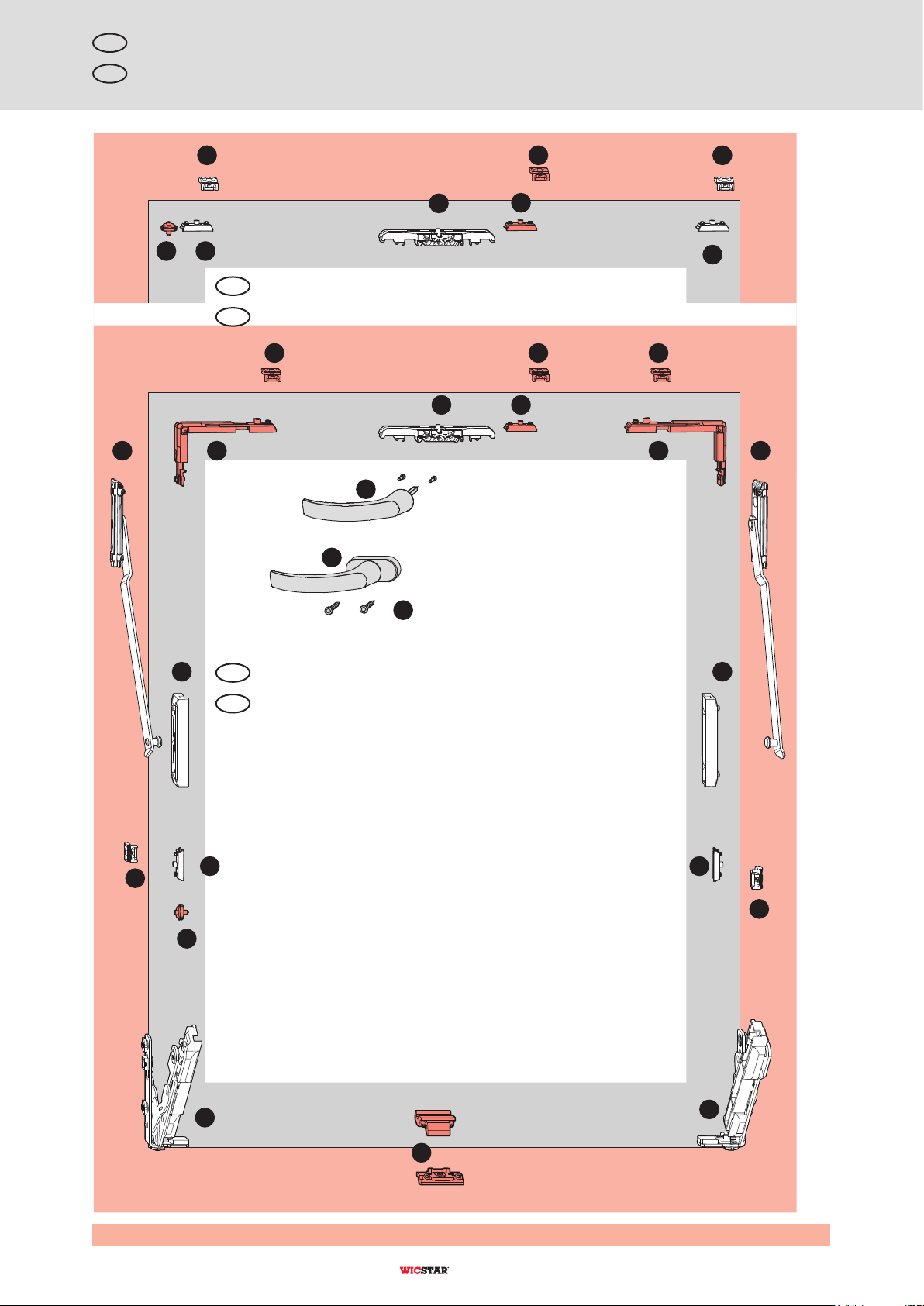
Le chiusure centrali verticali (T10) vanno applicate a
seconda dei profili e del relativo livello di usura (vedi
dimensioni anta consentite).
È richiesto il supporto asta di movimento se la distanza
fra i componenti è di 700 mm. È prescritto il montaggio
del dispositivo d’arresto ai sensi VOB-DIN 18360.
Se si usa la chiusura centrale del lato cerniera è
richiesto tassativamente il dispositivo d’arresto.
Gli angoli dei profili devono essere perpendicolari,
senza bavature e senza colla.
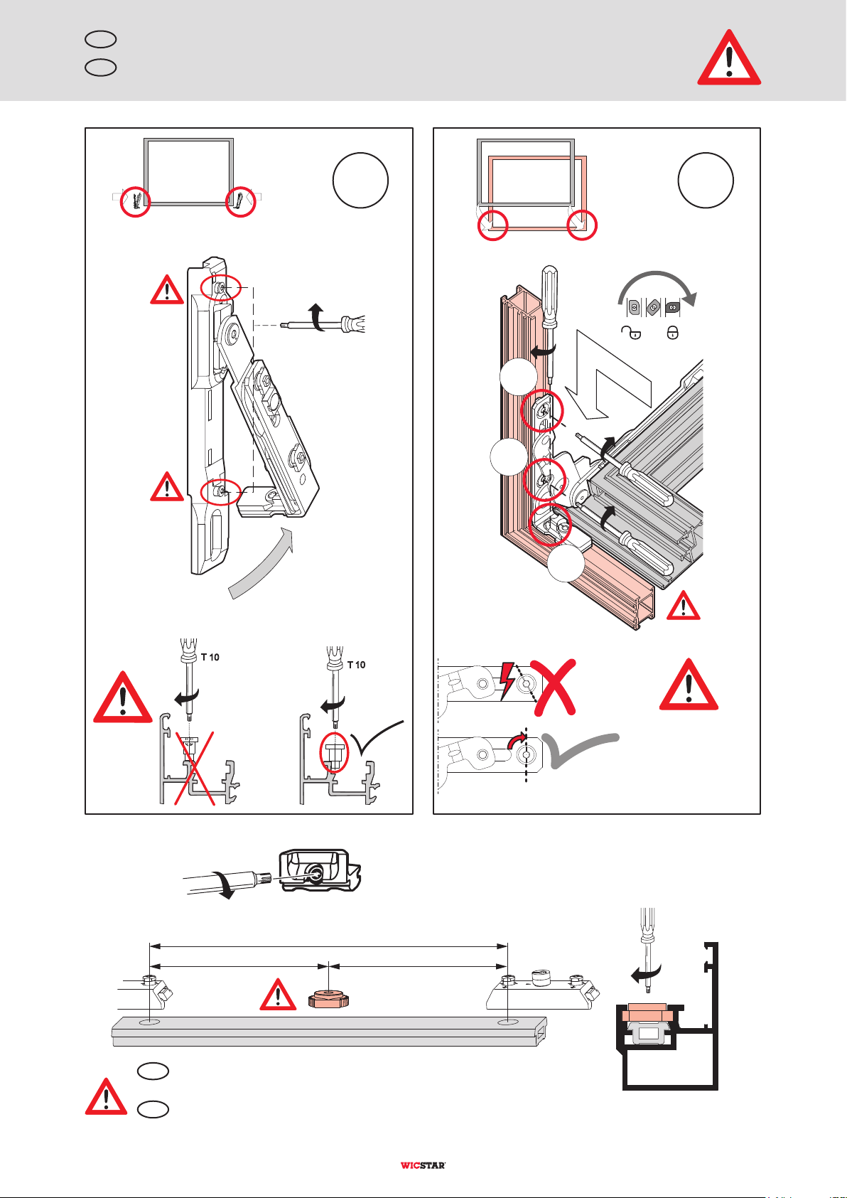
Una volta installata la finestra ne va verificato il
funzionamento. Per farlo, bisogna sganciare i fissaggi
centrali del movimento angolare e della cremonese
azionando una volta la maniglia.
I componenti mobili (soprattutto perni della cerniera,
sostegni angolari, aste di movimento e nottolini)
vanno trattati, prima del montaggio, con grasso
lubrificante WICPRO privo di acidi e resine.
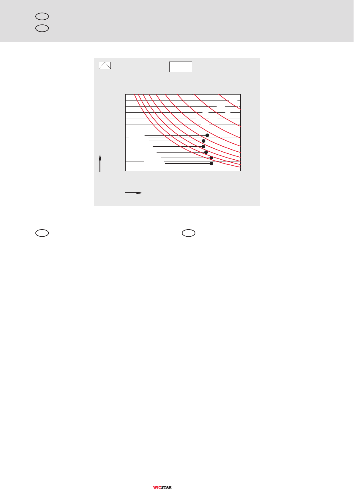
Per i pesi anta > 100 kg e le larghezze anta
FAB > 1400 mm sono richiesti fissaggi addizionali.
Il kit corrispondente va scelto a seconda del caso
specifico. Vedi le indicazioni di sicurezza.
DK/D (AR/AV) 160: peso anta > 100 kg (vedi diagramma).
Girare le viti di fissaggio del compasso finché non è
perforato il traversino del profilo.
Stringere le viti per fissare la cerniera con una
torsione di 3.5 – 4 N m .
Per il montaggio/lo smontaggio in loco dell’anta
(cerniera invisibile) è richiesto un angolo di ribalta di
almeno 90°.
Attenersi tassativamente alle indicazioni di sicurezza e
di montaggio del disegno di montaggio.
Misure in mm.
Estratto dalle norme sulla garanzia del prodotto
Attenersi anche alle norme e alle informazioni tecniche
sulla garanzia del prodotto. Il produttore di infissi deve
provvedere a fissare la ferramenta a regola d’arte (vedi
indicazioni di sicurezza del disegno di montaggio).
Rispettare le prescrizioni per il fissaggio dei vetri.
Non utilizzare materiali sigillanti a base di acidi, che
potrebbero corrodere la ferramenta.
Sicurezza funzionale della ferramenta
Per garantire la sicurezza funzionale continua della
ferramenta è necessario osservare quanto segue:
1. Montare correttamente i componenti della ferramenta
come indicato nelle relative istruzioni di montaggio.
2. Quando si installa la finestra montare gli elementi a
regola d’arte.
3. Rispettare le istruzioni di manutenzione e d’uso e
consegnarle all’utente.
4. La ferramenta completa deve essere composta
esclusivamente dai componenti del sistema originale.
L’utilizzo di componenti appartenenti ad altri sistemi
esclude ogni diritto di garanzia.
Garanzia del prodotto – esclusione di responsabilità
La nostra azienda non risponde dei difetti di funzionamento
né dei danni alla ferramenta stessa o alle finestre o
portefinestre dotate di tale ferramenta se questi sono da
ricondurre a capitolati incompleti o alla mancata
osservanza delle istruzioni di montaggio o dei diagrammi di
applicazione, o se i componenti della ferramenta sono
soggetti a forte imbrattamento. La garanzia vale solo ed
esclusivamente per i componenti originali. Non ci
assumiamo alcuna responsabilità per malfunzionamenti
dovuti alla mancata osservanza delle misure da rispettare,
al fissaggio non sicuro della ferramenta e all’applicazione
dei vetri non eseguita a regola d’arte. Dall’utilizzo della
presente documentazione non si può far derivare alcuna
pretesa giuridica. Salvo modifiche.
Tutti i dati riportati in questo opuscolo sono stati raccolti e
verificati accuratamente. Il progresso tecnologico, i cambia-
menti di legislazione e il passare del tempo comportano
inevitabili variazioni. Per questo motivo, non ci assumiamo
nessuna responsabilità per la correttezza e la completezza
dei contenuti.
Sono riservati tutti i diritti, in particolare il diritto di
riproduzione e diffusione.
Informazioni importanti
I
Per questa documentazione fanno testo le rispettive pagine aggiornate della gamma di prodotti WICONA. Vedi “Informazioni importanti”.
Certificazione DIN EN ISO 9001:2008

Mounting instructions
All slide rod bores to be Ø6 +0.1 mm.
Cutting tolerances for slide rod profiles ±0.5 mm.
Cutting tolerances for sash and frame ±1 mm.
Cutting tolerances for double casement sash and
burglary resistance sash ±0.5 mm.
All locking points are adjustable (±1 mm) with a Torx
screw driver T25.
Lateral adjustment of sash at the top retainer arm (T10):
Retainer arm Gr. 1 ±2 mm
Retainer arm Gr. 2 ±2 mm
Lateral adjustment of sash at the bottom (T25):
±1 mm.
Vertical adjustment of sash at the bottom (T25):
+2mm/-1 mm
Vertical centre locks (T10) to be used according to
profiles and the respective stress group (see
admissible sash sizes).
Slide rod holder is necessary if distance between two
components is ≥ 700 mm.
The profile corners must be at right angles, without
burrs and free of glue residues.
The good function of the window should be tested
after hardware installation. Initial handle operation
releases the centre fixings of corner trans mission and
gear.
The movable parts (especially bearing pins, corner
bearing, slide rods and locking pins) should be
treated with alkaline, resin-free WICPRO grease.
Turn the fastening screws of retainer arms until the
profile web is punched through.
For turn&tilt, tilt first, double casement hardware and
FAB > 1400 mm, a second retainer arm is necessary.
For turn&tilt, tilt first, double casement hardware and
FAB > 800 mm, a turn restrictor is recommended.
For turn&tilt, tilt first, double casement hardware and
FAB > 1300 mm or increased strain (schools,
hospitals or similar), a turn restrictor is necessary.
The use of a turn restrictor with brake is not permitted.
Ensure secure fit of all groove blocks. The groove
blocks must be turned by 90°.
On assembly and disassembly of the sash an
opening angle of at least 90° is necessary. (mind
required sapce).
Representations of safety instructions and mounting
instructions in the installation drawing should be strictly
observed.
All drawings are shown as a “DIN right-hand version”-
according to DIN German Industrial Norm (viewed from
inside). All dimensions are in mm.
Extracts from the guidelines for product liability
Please also consider the guidelines and technical
instructions with regard to product liability. The window
manufacturer should ensure that the metal hardware are
sufficiently secured (see safety instructions of installation
drawing). The shimming guidelines for glazing technique
should be complied with. Do not use acid polymerizing
sealing materials which could lead the metal hardware
parts to corrosion.
Functional safety of metal hardware
The following should be observed for durable functional
safety of metal hardware:
1. Professional assembly of metal hardware parts
according to the respective installation instruction.
2. Professional assembly of units.
3. Compliance with the maintenance and operating
instructions as well as its handing over to the user.
4. Complete hardware should consist of original system
parts. Use of parts alien to the system will lead to
exclusion of liability.
Product liability – Exclusion
We are not responsible for malfunctions or damages of
hardware as well as windows or window-doors (French
windows) equipped with damaged hardware subject to
insufficient tendering, non-observance of assembly
instructions or application diagrams or hardware parts
exposed to dirt accumulation. The warranty covers only
original components. We assume no liability for mal-
functions through non-compliance with the dimensions,
not secured fastening of hardware parts and
unprofessional glazing. Legal claims cannot be derived
from the use of these documents. Subject to alterations.
All the information have been gathered carefully and
checked. Modifications resulting through the techno-
logical progress, changes in the legislation as well as
through lapse of time are inevitable. Therefore, we cannot
assume warranty for the correctness and completeness of
contents.
All rights, especially the right of reproduction and
distribution are reserved.
Important information
GB
Valid are the respective documents of our WICONA programm. See “Important information”.
Certified in accorance with DIN EN ISO9001:2008
K-V 130
Salvo modiche. Sous réserve de modications. 40301 08.2019 5

130 kg
FAH 460 - 1700 mm
FAB 600 - 2500 mm
600
700
800
900
1000
1100
1200
1300
1400
1500
1600
1700
1800
1900
2000
2100
2200
2300
2400
2500
1400
1300
1200
1700
1600
1500
800
700
600
500
460
1100
1000
900
30kg/m²
40kg/m²
50kg/m²
60kg/m²
70kg/m²
80kg/m²
90kg/m²
100kg/m²
110kg/m²
120kg/m²
The represented diagram indicates the admissible format
sizes for tilt sashes. Especialy, these data are important
for broad sash formats where the sash width is larger
than the sash height. Please also pay attention to the data
on maximum and minimum sash sizes, the application of
vertical and horizontal centre locks as well as maximum
sash weights specified in the WICONA product range.
The specifications in the diagram are based on the
prescribed characteristics of resistance against wind
load, air permeability and tightness against driving rain
force of standard EN 14351 (July 2006) of products.
The represented format sizes in the diagram are valid only
for the application range of hardware. These sash sizes
are restricted through different profiles and the assumed
wind load by profile specific data. See tables of
„admissible sash sizes“ in the current WICONA
programme list.
Admissible format sizes
GB
Glass weight kg/m²
The values in the application diagram refer
to the max. sash weight.
GB
K-V 130
608.2019 40301 Salvo modiche. Sous réserve de modications.
Dal diagramma disponibile si ricavano le dimensioni
formato ammissibili per le ante a ribalta. Questi dati sono
particolarmente importanti per i formati orizzontali dell’anta,
in cui la larghezza dell’anta è maggiore dell’altezza. Tener
presente anche i dati specificati nella gamma di prodotti
WICONA e relativi alle dimensioni anta minime e massime,
all’uso di chiusure centrali verticali e orizzontali e ai pesi
massimi delle ante.
I dati del diagramma si basano sulle caratteristiche
assicurate di resistenza ai carichi del vento, permeabilità
all’aria e tenuta all’acqua della norma di prodotto
DIN EN 14351 (luglio 2006).
Le grandezze di formato riportate nel diagramma valgono
solo per il campo di applicazione della ferramenta. Queste
grandezze di formato sono limitate dai dati concernenti il
profilo, a partire da differenti profili e dal carico del vento
supposto. Vedi tabelle “Dimensioni anta consentite” della
gamma di prodotti Wicona.
Dimensioni formato ammissibili
I
Peso del vetro kg/m²
I dati del diagramma di applicazione indicano
il peso dell'anta massimo.
I

2.0 - 2.5 Nm
T 10
T 10
T 10
90°
≥700
==
T25 (3x)
1.5 - 2 Nm
3.
2.
1.
1. 2.
T10 (2x)
2 - 2.5 Nm
GB Safety instructions
Connecting rod safety-device needed, if length between two
hardware parts ≥700 mm.
GB
Ensure secure t of all
groove blocks!
K-V 130
Salvo modiche. Sous réserve de modications. 40301 08.2019 7
Indicazioni sulla sicurezza
I
È richiesto il fermo dell’asta di movimento se la distanza fra
due elementi è ≥700 mm.
I
Controllare che tutti i
ssaggi siano corretti!

A A
A A
AA
A
A
D
E
F
I
A
A
D
D
G H
A
A
C
B
B
B
A A
HB
B
G
GB Hardware overview
Alternative without vertical centre locks
GB
Alternative with vertical centre locks
GB
Red parts are not included in the basic set.
K-V 130
808.2019 40301 Salvo modiche. Sous réserve de modications.
IComposizione della ferramenta
Variante senza chiusure centrale verticale
I
Variante con chiusure centrale verticale
I
Gli elementi rossi non fanno parte del kit di base.

1 2
T10
21
2
1
T10
T10
Set
A
(1x) 6940514
B
(1x) 6940518
C
(1x) 6940302
D
(2x) 6960257
E
(1x) 6960259
F
(1x) 6960261
G
(1x) 6940287
H
(1x) 6940286
I
(2x) 6940095
RAB
RAH
RIH
RIB
FAB
FAH
FIB
FIH
FL
HG
FG
PZ
RZ
(represented) Order number
Hardware overview
GB
Description
Frame outer dimension
width
Frame outer dimension
height
Frame inner dimension
height
Frame inner dimension
width
Sash outer dimension
width
Sash outer dimension
height
Sash inner dimension
width
Sash inner dimension
height
Clearance
Handle height
Sash weight
Prole cylinder
Round cylinder
Disassembly Abbreviations
GB GB
GB
K-V 130
Salvo modiche. Sous réserve de modications. 40301 08.2019 9
(rafgurato) No. d’ordine
Composizione della ferramenta
I
Descrizione
larghezza esterna telaio
altezza esterna telaio
altezza interna telaio
larghezza interna telaio
larghezza esterna anta
altezza esterna anta
larghezza interna anta
altezza interna anta
aria battuta
maniglia altezza
peso anta
cilindro
cilindro tondo
Smontaggio Abbreviazioni
I I
I

22
22
30
30
43
Ø10Ø10
5060005
FAB - 2
FAB
B
A-A
A
B
A
B-B
Fixierung
Fixing
T25
T10
5910025
30
max. 28
L = 28 + X
X
L
{
+0.5
-1.0
/ Top
Punching or drilling figure for gear box and handle
GB
K-V 130
Salvo modiche. Sous réserve de modications. 40301 08.2019 11
sopra
Dime di foratura e punzonatura per cremonese e maniglia
I
fissaggio

RIB/2 + 160 (FAB < 2250)
106
RIB ±1
FAB/2 - 170
FAB/2 - 170
RIB ±1
FAB ±1
RIH ±1
RIH ±1
40 FAB/3 - 109
40
FAB/3 - 144
RIB/3 (FAB >2250) RIB/2
10
RIB/3 (FAB >2250)
T10
140
10
70 40
10
X + 128
10
40
40
10
RIB/3
(FAB >2250)
RIB/2
(FAB < 2250)
RIB/3
(FAB >2250)
X + 128
10
40
1.5
X + 80
Y
10
FAH ±1
X + 80
X
X
Y
4010
FAB/3-182
RIB/3 (FAB >2250) RIB/2
RIB/2 + 160 (FAB < 2250)
RIB ± 1
FAB/2-208
FAB/2 - 208
140
10
70 40
10
10
10
40
40 FAB/3 - 147
106
RIB/3 (FAB >2250)
90°
T10
12
1
2
I
10
20
6+0.1
10
3011015
1 2
III
T25 ±1 mm
-1 +1
A
±2 mm
T10
A
III
IV
IV
III
A
I
A
III
A
III
A
III
I
A
IV
A
III
A
III
A
III
A
III
A
III
A
III
A
V
V
Mounting and installation
GB
K-V 130
12 08.2019 40301 Salvo modiche. Sous réserve de modications.
Montaggio e installazione
I

RIB/2 + 160 (FAB < 2250)
106
RIB ±1
FAB/2 - 170
FAB/2 - 170
RIB ±1
FAB ±1
RIH ±1
RIH ±1
40 FAB/3 - 109
40
FAB/3 - 144
RIB/3 (FAB >2250) RIB/2
10
RIB/3 (FAB >2250)
T10
140
10
70 40
10
X + 128
10
40
40
10
RIB/3
(FAB >2250)
RIB/2
(FAB < 2250)
RIB/3
(FAB >2250)
X + 128
10
40
1.5
X + 80
Y
10
FAH ±1
X + 80
X
X
Y
4010
FAB/3-182
RIB/3 (FAB >2250) RIB/2
RIB/2 + 160 (FAB < 2250)
RIB ± 1
FAB/2-208
FAB/2 - 208
140
10
70 40
10
10
10
40
40 FAB/3 - 147
106
RIB/3 (FAB >2250)
90°
T10
12
1
2
I
10
20
6+0.1
10
3011015
1 2
III
T25 ±1 mm
-1 +1
A
±2 mm
T10
A
III
IV
IV
III
A
I
A
III
A
III
A
III
I
A
IV
A
III
A
III
A
III
A
III
A
III
A
III
A
V
V
K-V 130
Salvo modiche. Sous réserve de modications. 40301 08.2019 13

RIB/2 + 160 (FAB < 2250)
106
RIB ±1
FAB/2 - 170 FAB/2 - 170
RIB ±1
FAB ±1
RIH ±1
RIH ±1
40 FAB/3 - 109
40
FAB/3 - 144
RIB/3 (FAB >2250) RIB/2
10
RIB/3 (FAB >2250)
T10
140
10
70 40
10
X + 128
10
40
40
10
RIB/3
(FAB >2250)
RIB/2
(FAB < 2250)
RIB/3
(FAB >2250)
X + 128
10
40
1.5
X + 80
Y
10
FAH ±1
X + 80
X
X
Y
4010
FAB/3-182
RIB/3 (FAB >2250) RIB/2
RIB/2 + 160 (FAB < 2250)
RIB ± 1
FAB/2-208 FAB/2 - 208
140
10
70 40
10 10
10
40 40 FAB/3 - 147
106
RIB/3 (FAB >2250)
90°
T10
12
1
2
I
10
20
6
+0.1
10
3011015
1 2
III
T25 ±1 mm
-1 +1
A
±2 mm
T10
A
III
IV
IV
III
A
I
A
III
A
III
A
III
I
A
IV
A
III
A
III
A
III
A
III
A
III
A
III
A
V
V
Mounting and installation
GB
K-V 130
14 08.2019 40301 Salvo modiche. Sous réserve de modications.
Montaggio e installazione
I

RIB/2 + 160 (FAB < 2250)
106
RIB ±1
FAB/2 - 170 FAB/2 - 170
RIB ±1
FAB ±1
RIH ±1
RIH ±1
40 FAB/3 - 109
40
FAB/3 - 144
RIB/3 (FAB >2250) RIB/2
10
RIB/3 (FAB >2250)
T10
140
10
70 40
10
X + 128
10
40
40
10
RIB/3
(FAB >2250)
RIB/2
(FAB < 2250)
RIB/3
(FAB >2250)
X + 128
10
40
1.5
X + 80
Y
10
FAH ±1
X + 80
X
X
Y
4010
FAB/3-182
RIB/3 (FAB >2250) RIB/2
RIB/2 + 160 (FAB < 2250)
RIB ± 1
FAB/2-208 FAB/2 - 208
140
10
70 40
10 10
10
40 40 FAB/3 - 147
106
RIB/3 (FAB >2250)
90°
T10
12
1
2
I
10
20
6
+0.1
10
3011015
1 2
III
T25 ±1 mm
-1 +1
A
±2 mm
T10
A
III
IV
IV
III
A
I
A
III
A
III
A
III
I
A
IV
A
III
A
III
A
III
A
III
A
III
A
III
A
V
V
FAH X Y
>460 – 490 FAH/4 + 46 FAH/10 - 46
>490 – 530 FAH/4 + 57 FAH/10 - 31
>530 – 600 FAH/4 + 68 FAH/10 - 13
>600 – 1100 FAH/6 + 158 FAH/5 - 40
>1100 – 1500 FAH/4 + 168 FAH/4
>1500 – 1700 FAH/3 + 175 FAH/3
K-V 130
Salvo modiche. Sous réserve de modications. 40301 08.2019 15

5910043
5040000
5910025
5940019 (5040000)
5940038 (5040000) DK, TF, D, K
5940061
5940067 (5940061)
5940021 (5040000)
5940055 (5940061) 5940057 (5940061)
5960007 5060031
Templates and tools
GB
Drill jig
for link rod and turn lock device
Multi-function punching tool
consisting of pneumatic press
and tool carrier
Drill jig for rebate gear
Interchangeable tool
for handle with rosette
Interchangeable tool
for machining link rod
(for prole 3011015)
Single punching tool
for opening the sliding rod channels
Single punching tool
for processing slide rod
(for prole 3011015)
Interchangeable tool
for handle without rosette
Interchangeable tool
Single punching tool for
standard handle
Interchangeable tool
Single punching tool for
handle w/o rosette
Torx screw driver T 10 Torx screw driver T 25
K-V 130
16 08.2019 40301 Salvo modiche. Sous réserve de modications.
Dime e attrezzi
I
Dima di foratura per
lavorazione asta di movimento
e blocco apertura
Utensile per punzonatura multifunzionale
costituito da pressa pneumatica e
alloggiamento utensile
Dima di foratura per
maniglia standard e maniglia
senza rosetta
Utensile intercambiabile per
maniglia con rosetta
Utensile intercambiabile per
lavorazione asta di mov.
(per prolo 3011015)
Utensile di base
utensile di punzonatura unica per
aprire i canali dell’asta di mov.
Utensile di punzonatura unica per
lavorazione asta di mov.
(per prolo 3011015)
Utensile intercambiabile per
maniglia senza rosetta
Inserto intercambiabile
utensile di punzonatura unica per
maniglia standard
Inserto intercambiabile
utensile di punzonatura unica per
maniglia senza rosetta
Cacciavite Torx T10 Cacciavite Torx T25
This manual suits for next models
1
Popular Landscape Lighting manuals by other brands

Malibu Boats
Malibu Boats LZ6 instructions

Regent Lighting Solutions
Regent Lighting Solutions Voyager 1 installation instructions

LIGMAN
LIGMAN ITAC 2 installation manual

Volt
Volt VUL-6703 BBZ Series installation instructions

Connext
Connext Ellumiere 01EL062 instruction manual

Malibu Boats
Malibu Boats LZ14001H instructions