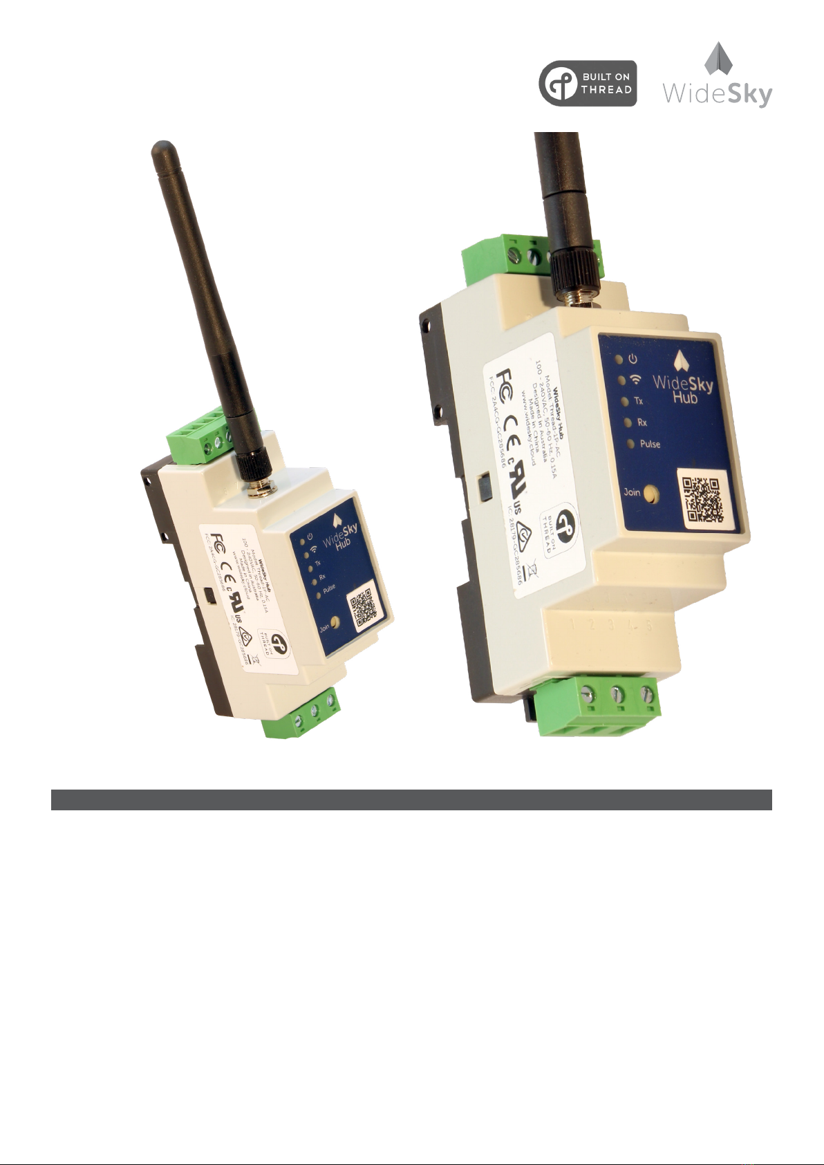
WideSky Hub 1P-AC User manual

Installation Guide
WideSky® Hub 1P-AC
For more information visit: widesky.cloud and cetameter.com 1
Specifications & Intended Use
Electrical
• Voltage: 100-240Vac, 50/60Hz
• Max Load: 1W
• Operation Temp: -20 to +70°C (-4 to +158°F)
• Operating Humidity: 5-95% RH
RS485
• Modbus Master
• Serial Gateway
Pulse In
• 600 p/min (100ms debounce)
• Wet Contact, pulled up to 5V
Wireless
• Max. Transfer Rate 250kbps
• ThreadCertied
This device is designed for installation in an enclosure and is intended for commercial use, such as in metering, monitoring,
measurement, information or communication equipment or the like. If this device is used in a manner outside of its
specication,theprotectionprovidedbythedevicemaybeimpaired.

Installation Guide
WideSky® Hub 1P-AC
For more information visit: widesky.cloud and cetameter.com 2
Installation Instructions
WARNING: Risk of electrical shock, fire, personal injury or death.
The device is designed, tested and approved for branch circuits up to 20A without additional protection device. If an
external fuse is utilised, do not use circuit breakers smaller than 6A nor use circuit breakers with B or C characteristic to
avoid a nuisance tripping.
• This device may only be installed and put into operation by qualified personnel.
• Turn power o before working on the device and protect against inadvertent re-powering.
• Device does not contain serviceable parts - Do not open, modify or attempt to repair.
• The maximum transmission power is fixed by user inaccessible software configurations to the region’s regulatory
limits.
• If damage or malfunction should occur during installation or operation turn o power and send unit to WideSky for
inspection.
• Install device in an enclosure providing protection against electrical, mechanical and fire hazards.
• Install the device onto a DIN rail according to EN 60715 with the mains power input terminals facing the bottom.
• Make sure that the wiring is correct by following all local and national codes.
• Fasten terminals with a maximum torque of 0.5Nm - Unused screw terminals should be securely tightened.
• The device is designed for pollution degree 2 areas in controlled environments. No condensation or frost is allowed.
• The device is suitable to be supplied from TN, TT or IT mains networks. The continuous voltage between the input
terminal and the PE potential must not exceed 240VAC.
• A disconnecting means shall be provided for the mains input of the device.
No Description
1 Line
2 Protective Earth
3 Neutral
4 Not Used
5 Not Used
6 Common (Ground)
7 Not Used
8 Pulse In
9 RS485: D-
10 RS485: D+
11 Power Indicator
12 Thread Network Connect Indicator
13 RS485 Transmit Indicator
14 RS485 Receive Indicator
15 Pulse In Indicator
16 Join Thread Mesh Network Button
17 SMA Antenna Connector

Installation Guide
WideSky® Hub 1P-AC
For more information visit: widesky.cloud and cetameter.com 3
Support
Please contact WideSky® or an authorized representative; for Thread commissioning instructions contact authorised
WideSky® representative.
Compliance Declarations
Federal Communications Commission
This device complies with Part 15 of the FCC Rules. Operation is subject to the following two conditions: (1) this device may not cause
harmful interference, and (2) this device must accept any interference received, including interference that may cause undesired
operation.
Caution: The user is cautioned that changes or modifications not expressly approved by the party responsible for compliance could void
the user’s authority to operate the equipment.
Note: This equipment has been tested and found to comply with the limits for a Class B digital device, pursuant to part 15 of the FCC
Rules. These limits are designed to provide reasonable protection against harmful interference in a residential installation. This equipment
generates uses and can radiate radio frequency energy and, if not installed and used in accordance with the instructions, may cause
harmful interference to radio communications. However, there is no guarantee that interference will not occur in a particular installation.
If this equipment does cause harmful interference to radio or television reception, which can be determined by turning the equipment o
and on, the user is encouraged to try to correct the interference by one or more of the following measures:
• Reorient or relocate the receiving antenna.
• Increase the separation between the equipment and receiver.
• Connect the equipment into an outlet on a circuit dierent from that to which the receiver is connected.
• Consult the dealer or an experienced radio/TV technician for help.
Industry Canada / Industrie Canada
This device complies with Industry Canada license-exempt RSSs. Operation is subject to the following two conditions:
1. This device may not cause interference, and
2. This device must accept any interference, including interference that may cause undesired operation of the device.
Le présent appareil est conforme aux CNR d’Industrie Canada applicables aux appareils radio exempts de licence. L’exploitation est
autorisée aux deux conditions suivantes :
1. l’appareil ne doit pas produire de brouillage;
2. l’utilisateur de l’appareil doit accepter tout brouillage radioélectrique subi, meme si le brouillage est susceptible d’en compromettre le
fonctionnement.
Radiation Exposure Statement / Déclaration d’exposition aux radiations
This equipment complies with IC radiation exposure limits set forth for an uncontrolled environment. This equipment should be installed
and operated with a minimum distance of 20cm between the radiator & your body.
Cet équipement est conforme aux limites d’exposition aux rayonnements IC établies pour un environnement non contrôlé. Cet
équipement doit être installé et utilisé avec un minimum de 20 cm de distance entre la source de rayonnement et votre corps.
European Conformity / Conformité Européenne
This device complies with the
• Harmonized Standard for the Radio Equipment Directive
• Assessment of Electronic and Electrical Equipment related to human exposure restrictions for Electromagnetic Fields Standard
• Radiocommunications EMC standards.
Australian Communications and Media Authority
This device complies with the
• Radiocommunications (Electromagnetic Compatibility) Standard
• Radiocommunications (Short Range Devices) Standard
• Radiocommunications (Electromagnetic Radiation Human Exposure) Standard
• Audio/Video, Information and Communication Technology Equipment Part 1: Safety Requirements Standard
Dispose according to local regulations for Electrical and Electronic Waste.
FCC: 2A4CG-GC285686
IC: 28179-GC285686

Installation Guide
WideSky® Hub 1P-AC
For more information visit: widesky.cloud and cetameter.com 4
Wireless Mesh Topology Tips
To maximise the performance of a mesh network the antennas on the WideSky® Hub devices should be adjusted so that they
are parallel to each other as shown in Fig 1. This is because most of the transmission energy is radiated perpendicular to the
antenna as shown in Fig 2.
Fig 1 Multiple antenna orientation
Fig 2 Antenna radiation pattern
Antenna Wave Direction
Single-level
Building
Multi-level
Building
Antenna WideSky Hub

Installation Guide
WideSky® Hub 1P-AC
For more information visit: widesky.cloud and cetameter.com 5
Wireless Mesh Topology Tips
The environment and placement of wireless devices have a major impact on the performance of the system. Also consider
that moveable furniture and equipment will have an impact. Example a new metal storage cabinet in an adjacent room can
interrupt a previously reliable connection.
Avoidplacingwirelessdevicesontheoorordirectlyontoconcreteslabceilings,consideradditionalrepeaterhubswhen
connecting to basements and cellars.
Avoid placing antennas inside metal enclosures such as steel distribution boards, use external antennas.
Fig 3 Dierent materials aect (or attenuate) wireless networks dierently.
Materials that have high signal attenuation properties
(are bad for wireless networks)
Materials that have low signal attenuation properties
Masonry
Glass & Plastic
Steel
Wood
Concrete &
Reinforced Concrete
Trees

Installation Guide
WideSky® Hub 1P-AC
For more information visit: widesky.cloud and cetameter.com 6
Wireless Mesh Topology Tips
The physical location of WideSky hubs (nodes) in a mesh relative to each other and the border router/s are critical to the
performance and resilience of the wireless network. Some general good design principles are:
• Ensure that there is more than one path from each node to the border router.
• Avoid single points of failure in the network, linear networks are particularly prone to this.
• Preferably keep data hops to less than 4, system latency and reliability can be compromised with larger numbers.
Fig 4 Wireless mesh design topologies impact performance and reliability.
Node (WideSky Hub) Border router connected to www
(WideSky Hub + Router)
Avoid
Better
Good
Excellent
Table of contents