Wieland gesis User manual

Manual
Doc. No. BA001281
Last Update: 04/2022 (Rev. A)
gesis
®WIV
System distributor for temporary electrical installations

Info
Wieland Electric
GmbH | BA001281 | 04/2022 (Rev. A)
2
NOTES
This work is copyrighted material. The resulting rights remain with Wieland Electric GmbH. Any du-
plication of this document or parts thereof is permitted only within the limits of the statutory provi-
sions of the Copyright Act. Alteration or abridgement of this document without the express written
consent of Wieland Electric GmbH is prohibited.
gesis®is a trademark of Wieland Electric GmbH. Other product and brand names mentioned in this
manual are trademarks or registered trademarks of their respective owners. The use of these names
and trademarks by third parties for their own purposes may infringe the owner's rights.

Table of contents
Wieland Electric
GmbH | BA001281 | 04/2022 (Rev. A)
3
TABLE OF CONTENTS
1About this manual 5
1.1 Scope of application 5
1.2 Function of this document 5
1.3 Target group 5
1.4 Function and structure of this manual 5
1.5 Symbols and notations 6
2Safety 7
2.1 Intended use 7
2.2 CE declaration 7
3General product information 8
3.1 Product description 8
3.2 Symbols on the product 8
4Technical data 9
4.1 gesis®WIV GST18®outlets 9
4.2 gesis®WIV GST15 outlets 11
4.3 gesis®WIV with RST20 outlets 13
5Dimensions 15
6Mounting 17
6.1 Preparation 17
6.2 Mounting the system distributor 17
6.3 Connecting the leads 18
6.3.1 Connections pluggable with cable assemblies 18
6.3.2 Connections pluggable with self-assembled connectors 18
6.3.3 Connecting the earthing point 18
7Possible system layout 19
8Commissioning 20
9Operation 21
9.1 Type of outlets 21
9.1.1 Switchable outlets 21
9.1.2 Non-switchable outlets 21
9.2 Use of the 40 kVA distributor 22
9.3 Measuring device 22

About this manual
Wieland Electric
GmbH | BA001281 | 04/2022 (Rev. A)
5
1ABOUT THIS MANUAL
Please read this chapter carefully before using the user manual or the products.
1.1 Scope of application
This manual is valid for the following product family: System distributor - gesis®WIV.
1.2 Function of this document
This manual supports you in the project planning electrical systems and the assembly, installation,
commissioning, maintenance and disposal of the system distributors. You will find notes on how the
devices can be implemented.
This document contains the information required for the intended use of the device as well as tech-
nical data. It describes the technical characteristics and how to use the system components.
Hand over the documentation to the owner after successful installation and/or initial commission-
ing.
1.3 Target group
This manual is intended for:
•Those who can prove that they have the corresponding training and already have correspond-
ing basic knowledge of project planning and commissioning electrical installations.
•System integrators
•Electricians
•Operator of the electrical system
1.4 Function and structure of this manual
This user manual provides technical staff with information concerning the installation, operation
and functionality of gesis®WIV system distributors.
You can find further information on our website www.wieland-electric.de or via the QR code.
NOTE

About this manual
Wieland Electric
GmbH | BA001281 | 04/2022 (Rev. A)
6
1.5 Symbols and notations
Information that warns of personal injury or property damage are emphasized by safety instruc-
tions.
The symbol "DANGER" indicates an immediate danger. Failure to observe this symbol may result in
serious injury or death.
"DANGER" is used to warn of dangers which are, at the time of the warning, already existing (e.g.,
hot surfaces, sharp edges, crush points, etc.)
It is used exclusively in danger of personal injury!
The "WARNING" symbol indicates a possible danger. Failure to observe this symbol may result in se-
rious injury.
The "CAUTION" symbol indicates a possible danger. Failure to observe this symbol may result in mi-
nor injuries.
Notes concerning the special functions of the device.
Instructions also advise you of a potentially dangerous situation. If the symbol is not observed, it
can lead to damage to the system or the system environment.
DANGER
WARNING
CAUTION
NOTE

Safety
Wieland Electric
GmbH | BA001281 | 04/2022 (Rev. A)
7
2SAFETY
To avoid personal injury and/or material damage, please read the following safety instructions and
follow them at all times:
•This manual is part of the product. It must be read and followed.
•As the operator of the electrical system, keep the manual accessible at all times or, as the in-
staller, hand over the document to the operator of the electrical system after successful installa-
tion and commissioning.
•Damaged products must neither be installed nor put into operation.
•Protective measures and mechanisms must correspond to applicable regulations.
•All international, national and regional guidelines, standards, safety instructions and safety reg-
ulations must be observed throughout the entire life cycle of the product.
•The system distributor complies with IEC 61439 low-voltage switching device combinations. For
system distributors with measuring equipment, the national and regional guidelines, and EMC
standards must be observed.
•Never use components from third-party manufacturers. No guarantee shall be offered for dam-
age resulting from a combination with third-party components.
•The name plate must not be removed and must be permanently attached to the system distrib-
utor.
•This system distributor has been designed, produced and tested in accordance with the applica-
ble safety requirements. Despite the greatest care, it can pose a safety risk - as can all electro-
technical / electronic components and products.
2.1 Intended use
The gesis®WIV system distributor is intended for either indoor or outdoor use, depending on the
model.
Indoor operation:
•gesis®CLASSIC
•gesis®MINI
Operation in protected outdoor areas:
•RST®
Observe the safety instructions and technical data listed in this manual (see chapter 4 "Technical
data").
2.2 CE declaration
You can find the relevant CE declaration at: https://eshop.wieland-electric.com or via the QR code
below. Navigate to the download area of your product. You will then find the CE declaration under
the item "EC Declaration of Conformity".

General product information
Wieland Electric
GmbH | BA001281 | 04/2022 (Rev. A)
8
3GENERAL PRODUCT INFORMATION
3.1 Product description
The product is a pre-wired system distributor for pluggable electrical installation with gesis®CLAS-
SIC / gesis®MINI / RST®CLASSIC. The outlets are pluggable via the installation connector system ap-
proved in accordance with DIN EN 61535 gesis®CLASSIC / gesis®MINI / RST®CLASSIC.
The connected load is 20 kVA or 40 kVA.
The product has switchable and non-switchable outputs. All outputs are internally protected by cir-
cuit breakers. Switchable outlets can be switched via a main switch.
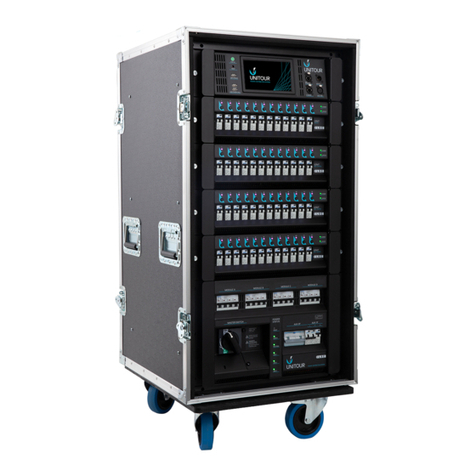
Figure 1: gesis®WIV system distributor for temporary installation
3.2 Symbols on the product
The following symbols can be found on the product.
Conductor identification yellow/green conductor earth
CE marking
For disposal, this product should be treated as electrical and electronic equip-
ment waste and should not be disposed of as household waste.
EAK: 16 02 16

Technical data
Wieland Electric
GmbH | BA001281 | 04/2022 (Rev. A)
9
4TECHNICAL DATA
In the following tables you will find the technical data of the installation distributor.
The technical data of customer-specific installation distributors may vary.
4.1 gesis®WIV GST18®outlets
Item number
Without measuring device
93.053.6009.0
93.053.6010.0
93.053.7006.0
93.053.7007.0
With measuring device
93.053.6009.1
93.053.6010.1
93.053.7006.1
93.053.7007.1
Description
20 kVA
20 kVA
40 kVA
40 kVA
Power supply system
Measuring device
optional
optional
optional
optional
Connected load, CEE 32 A on RST50
20 kVA
20 kVA
40 kVA**
40 kVA**
Max. pre-fuse
32 A
32 A
63 A
63 A
Pluggable with
RST50
RST50
CEE 63 A*
CEE 63 A*
Connection cable length
3 m***
3 m***
3 m
3 m
Outputs (GST18®and safety sockets)
Plug system gesis
®
CLASSIC
GST18
®
GST18
®
GST18
®
GST18
®
Total output power
20 kVA
20 kVA
40 kVA
40 kVA
Switchable, white connectors
1-phase, 3-pole
12
6
9
6
3-phase, 5-pole
1
3
1
3
Non-switchable, black connectors
1-phase, 3-pole
2
3
3
3
3-phase, 5-pole
–
1
–
–
Safety socket
2
2
1
1
Protective/switching devices for the outputs
Residual current circuit breaker, 4-pole, 40 A, 30 mA
1
1
1
1
Circuit breaker, 1-pole, B, 16 A
14
11
12
10
Circuit breaker, 3-pole, B, 16 A
1
4
1
3
Main switch 63 A
1
1
1
1
Routing
Power
–
–
20 kVA
20 kVA
Pluggable with
–
–
RST50
RST50
Cable included, length
–
–
1 m
1 m
Protected with circuit breaker
–
–
B, 32A
B, 32A
* Lead is connected in the distributor
** 20 kVA direct outlets + 20 kVA fused outlet for a 20 kVA distributor
*** Connection cable CEE 32A to RST50 included in scope of delivery

Technical data
Wieland Electric
GmbH | BA001281 | 04/2022 (Rev. A)
10
Other technical data
Housing material
Robust polycarbonate
Color housing
Electric gray
Switchgear and controlgear assemblies
IEC 61439
Environmental specifications
For dry rooms only
Protection rating
Without mating connector
IP20
With mating connector
IP40
Mounting method
Wall Mounting
Circuit diagram
Included in scope of delivery
Parts list and dimensional drawing
Upon request
Switchable outputs
•White connectors
•Residual current and circuit breakers
•Switchable with main switch
Non-switchable outputs
•
Black connectors
•Safety sockets
•Residual current and circuit breakers
•Wired directly
Transfer, on the 40 kVA distributor
•
RST50 / 5-pole
•Circuit breaker, 3-pole, B, 32 A

Technical data
Wieland Electric
GmbH | BA001281 | 04/2022 (Rev. A)
11
4.2 gesis®WIV GST15 outlets
Item number
Without measuring device
93.053.4001.0
93.053.4101.0
With measuring device
93.053.4001.1
93.053.4101.1
Description
20 kVA
40 kVA
Power supply system
Measuring device
optional
optional
Connected load, CEE 32 A on RST50
20 kVA
40 kVA**
Max. pre-fuse
32 A
63 A
Pluggable with
RST50
CEE 63 A
Connection cable length
3 m***
3 m*
Outputs (GST15 and safety sockets)
gesis
®
plug system
GST15
GST15
Total output power
20 kVA
40 kVA
Switchable, white connectors
1-phase, 3-pole
12
9
3-phase, 5-pole
1
1
Non-switchable, black connectors
1-phase, 3-pole
2
3
Safety socket
2
1
Protective/switching devices for the outputs
Residual current circuit breaker, 4-pole, 40 A, 30 mA
1
1
Circuit breaker, 1-pole, B, 16 A
14
12
Circuit breaker, 3-pole, B, 16 A
1
1
Main switch 63 A
1
1
ROUTING
Power
–
20 kVA
Pluggable with
–
RST50
Cable included, length
–
1 m
Protected with circuit breaker
–
B, 32A
* Lead is connected in the distributor
** 20 kVA direct outlets + 20 kVA fused outlet for a 20 kVA distributor
*** Connection cable CEE 32A to RST50 included in scope of delivery

Technical data
Wieland Electric
GmbH | BA001281 | 04/2022 (Rev. A)
12
Other technical data
Housing material
Robust polycarbonate
Color housing
Electric gray
Switchgear and controlgear assemblies
IEC 61439
Environmental specifications
For dry rooms only
Protection rating
Without mating connector
IP20
With mating connector
IP40
Mounting method
Wall Mounting
Circuit diagram
Included in scope of delivery
Parts list and dimensional drawing
Upon request
Switchable outputs
•White connectors
•Residual current and circuit breakers
•Switchable with main switch
Non-switchable outputs
•
Black connectors
•Safety socket
•Residual current and circuit breakers
•Wired directly
Transfer, on the 40 kVA distributor
•
RST50 / 5-pole
•Circuit breaker, 3-pole, B, 32 A

Technical data
Wieland Electric
GmbH | BA001281 | 04/2022 (Rev. A)
13
4.3 gesis®WIV with RST20 outlets
Item number
Without measuring device
93.053.9001.0
93.053.9101.0
With measuring device
93.053.9001.1
93.053.9101.1
Description
20 kVA
40 kVA**
Power supply system
Measuring device
optional
optional
Connected load, CEE 32 A on RST50
In scope of delivery
–
Max. pre-fuse
32 A
63 A
Pluggable with
RST50
CEE 63 A*
Connection cable length
3 m***
3 m*
Outputs (RST20)
Plug system RST
®
CLASSIC
RST20
RST20
Total output power
20 kVA
40 kVA
Switchable, light gray connector
1-phase, 3-pole
6
6
3-phase, 5-pole
2
2
Non-switchable, black connectors
1-phase, 3-pole
3
2
3-phase, 5-pole
1
–
Protective/switching devices for the outputs
Residual current circuit breaker, 4-pole, 40 A, 30 mA
1
1
Circuit breaker, 1-pole, B, 16 A
9
8
Circuit breaker, 3-pole, B, 16 A
3
2
Main switch 63 A
1
1
Routing
Power
–
20 kVA
Pluggable with
–
RST50
Cable included, length
–
1 m
Protected with circuit breaker
–
B, 32A
* Lead is connected in the distributor
** 20 kVA direct outlets + 20 kVA fused outlet for a 20 kVA distributor
*** Connection cable CEE 32A to RST50 included in scope of delivery
**** Protect the installation distributor and connection cable with CEE plug from direct weathering
and UV exposure.

Technical data
Wieland Electric
GmbH | BA001281 | 04/2022 (Rev. A)
14
Other technical data
Housing material
Robust polycarbonate
Color housing
Electric gray
Switchgear and controlgear assemblies
IEC 61439
Environmental specifications
For protected outdoor areas
Protection rating
Without mating connector
IP20
With mating connector
IP44
Mounting method
Wall Mounting
Circuit diagram
Included in scope of delivery
Parts list and dimensional drawing
Upon request
Switchable outputs
•Light gray connector
•Residual current and circuit breakers
•Switchable with main switch
Non-switchable outputs
•
Black connectors
•Residual current and circuit breakers
•Wired directly
Transfer, on the 40 kVA distributor
•
RST50 / 5-pole
•Circuit breaker, 3-pole, B, 32 A

Dimensions
Wieland Electric
GmbH | BA001281 | 04/2022 (Rev. A)
15
5DIMENSIONS
Description Item number Drill hole dimension
width / height
Device dimensions W × H × D
Required installation space
incl. minimum distance*
GST18®
93.053.6009.0
230 mm / 485 mm
315 × 630 × 156 mm
415 × 1230 × 156 mm
93.053.6009.1
230 mm / 635 mm
315 × 780 × 156 mm
415 × 1380 × 156 mm
93.053.6010.0
230 mm / 635 mm
315 × 780 × 156 mm
415 × 1380 × 156 mm
93.053.6010.1
230 mm / 785 mm
315 × 930 × 156 mm
415 × 1530 × 156 mm
93.053.7006.0
230 mm / 485 mm
315 × 630 × 156 mm
415 × 1230 × 156 mm
93.053.7006.1
230 mm / 635 mm
315 × 780 × 156 mm
415 × 1380 × 156 mm
93.053.7007.0
230 mm / 635 mm
315 × 780 × 156 mm
415 × 1380 × 156 mm
93.053.7007.1
230 mm / 785 mm
315 × 930 × 156 mm
415 × 1530 × 156 mm
GST15
93.053.4001.0
230 mm / 485 mm
315 × 630 × 156 mm
415 × 1230 × 156 mm
93.053.4001.1
230 mm / 635 mm
315 × 780 × 156 mm
415 × 1380 × 156 mm
93.053.4101.0
230 mm / 485 mm
315 × 630 × 156 mm
415 × 1230 × 156 mm
93.053.4101.1
230 mm / 635 mm
315 × 780 × 156 mm
415 × 1380 × 156 mm
RST®
93.053.9001.0
230 mm / 485 mm
315 × 630 × 156 mm
415 × 1230 × 156 mm
93.053.9001.1
230 mm / 635 mm
315 × 780 × 156 mm
415 × 1380 × 156 mm
93.053.9101.0
230 mm / 485 mm
315 × 630 × 156 mm
415 × 1230 × 156 mm
93.053.9101.1
230 mm / 635 mm
315 × 780 × 156 mm
415 × 1380 × 156 mm
Table 1: Overview of dimensions gesis®WIV
* Front side open
Figure 2: Front and side view gesis®WIV, height 630 mm

Dimensions
Wieland Electric
GmbH | BA001281 | 04/2022 (Rev. A)
16
Figure 3: Front and side view gesis®WIV, height 780 mm
Figure 4: Front and side view gesis®WIV, height 930 mm

Mounting
Wieland Electric
GmbH | BA001281 | 04/2022 (Rev. A)
17
6MOUNTING
All international, national and regional guidelines, standards, safety instructions and safety regula-
tions must be observed throughout the entire life cycle of the product.
The assembly of the components is the exclusive responsibility of skilled personnel. The legally
binding and valid regulations for electrical installations must be observed.
6.1 Preparation
Check that the system distributors are undamaged before starting installation. Do not use and in-
stall any damaged distributors and components.
Observe all necessary safety precautions and carry out all work preparations before proceeding with
mounting.
Read all the included data sheets and manuals before mounting the distributor.
Observe the technical data of the product, see chapter 4 "Technical data".
6.2 Mounting the system distributor
In the first step, the system distributors are to be mounted, if necessary, with the existing mounting
options on or on a suitable base provided for this purpose.
Make sure that:
•suitable mounting material is used.
•the system distributors are mounted vertically.
•the system distributors are adequately mechanically fastened.
•the system distributors are only mounted on the designated mounting surface.
•the system distributors are not enclosed or covered.
•the system distributors are mounted with the specified minimum distances:
◦upwards/downwards: min. 300 mm
◦to the left/right: min. 50 mm
•all necessary protective conductor connections have been made at the end of the installation.
•the system distributors are always easily accessible for visual checks and maintenance work.
•the system distributor is not exposed to direct sunlight. Exposure to sunlight can lead to an un-
authorized increase in temperature, malfunction and premature aging of the components and
the housing.

Mounting
Wieland Electric
GmbH | BA001281 | 04/2022 (Rev. A)
18
6.3 Connecting the leads
The plugging in of the connectors or the connection of the cables must only be carried out after the
system distributor has been installed.
6.3.1 Connections pluggable with cable assemblies
All connectors can be plugged in without requiring any tools. Always make sure that the mechanical
and color coding are the same, and that the connector is in the right direction.
Disconnecting connectors
Notes on pulling the connectors can be found in the respective product catalog or in the assembly
instructions for the connector in question.
Connector / measures
gesis®
CLASSIC
gesis®
MINI
RST®
CLASSIC
RST®
POWER
Safety socket
CEE
Create load relief
X
X
X
X
–
–
Release interlock
X
X
X
X
–
X
To disconnect the connector, it is not necessary to open the system distributor. The internal wiring
on the connector is done at the factory.
6.3.2 Connections pluggable with self-assembled connectors
The technical data, as well as the assembly instructions for the installation connector can be found
under https://eshop.wieland-electric.com for the respective connector, or in the corresponding in-
struction leaflet.
You can find the mounting steps in the assembly instructions of the corresponding installation con-
nector.
All connectors can be plugged in without requiring any tools. Always make sure that the mechanical
and color coding are the same, and that the connector is in the right direction.
Disconnecting connectors
Notes on removing the connectors can be found in the respective product catalog or in the assembly
instructions for the connector in question.
Connector / measures
gesis®
CLASSIC
gesis®
MINI
RST®
CLASSIC
RST®
POWER
Safety socket
CEE
Create load relief
X
X
X
X
–
–
Release interlock
X
X
X
X
–
X
To remove the connector, it is not necessary to open the system distributor. The internal wiring on
the connector is done at the factory.
6.3.3 Connecting the earthing point
For earthing metal parts, e.g. for the exhibition stand, connect the M8 cable lug to the earthing con-
nection at the bottom of the system distributor housing in accordance with the standard (cross-sec-
tion depends on the distributor). The mounting frame with earthing point is earthed via M8 bolts.
NOTE
NOTE
NOTE

Possible system layout
Wieland Electric
GmbH | BA001281 | 04/2022 (Rev. A)
19
7POSSIBLE SYSTEM LAYOUT
Figure 5: Possible system layout
The gesis®WIV system distributor is a holistic system for the energy supply of a temporary installa-
tion thanks to the gesis®CLASSIC, gesis®MINI or RST®CLASSIC components.
The following articles can be added to the gesis®WIV system distributor - sample listing:
Additional components (illustrative) Valid for
1.
gesis®CLASSIC h-distributor, 3-pole (1 input, 2 outputs)
2. gesis®CLASSIC h-distributor, 3-pole (1 input, 3 outputs)
3. gesis®CLASSIC extension cable 3G1.5 or 3G2.5
4. gesis®WIV system distributor for temporary installation
5. gesis®cascadable multiple socket
6. gesis®CLASSIC T-distributor, 3-pole (1 input, 2 outputs)
7. gesis®CLASSIC connection cable 3G2.5
93.053.6009.0
93.053.6009.1
93.053.6010.0
93.053.6010.1
93.053.7006.0
93.053.7006.1
93.053.7007.0
93.053.7007.1
In the same way as the gesis®CLASSIC installation connectors, components from the gesis®MINI or
RST®CLASSIC range can also be used. The system distributor models must match the corresponding
installation connector system. You can find the corresponding accessories at https://eshop.wieland-
electric.com.
1
7
6
5
4
3
2
3

Commissioning
Wieland Electric
GmbH | BA001281 | 04/2022 (Rev. A)
20
8COMMISSIONING
All international, national and regional guidelines, standards, safety instructions and safety regula-
tions must be observed throughout the entire life cycle of the product.
The commissioning of the components is the exclusive responsibility of skilled personnel. The le-
gally binding and valid regulations for electrical installations must be observed.
The distributor is fully functional once it has been mounted and installed correctly. It may be neces-
sary to reset e.g. the switching and protective devices. If necessary, carry out a functional test of the
switching and protective elements.
System distributors with electronic components may require commissioning and configuration. The
necessary manuals are enclosed with the system distributor and can be found on the manufactur-
er's homepage.
During installation and commissioning, you must make sure that the necessary EMC directives are
complied with.
For further details on the mechanical or electrical data, see the enclosed documentation in the
scope of delivery or at https://eshop.wieland-electric.com
This manual suits for next models
22
Table of contents

