DEUTSCH ENGLISH FRANÇAIS
Systemmodule System modules Modules système
Hinweis
Dieses Handbuch beschreibt nur das:
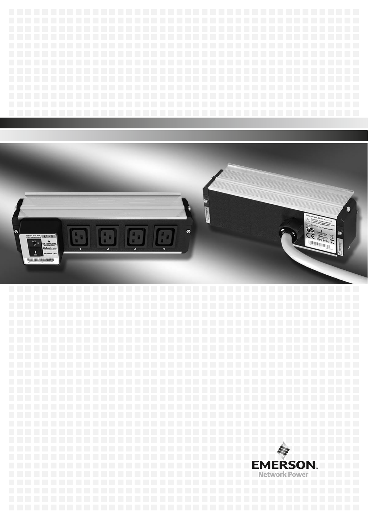
Stromeingangsmodul MPX PEM–
Elementary sowie das
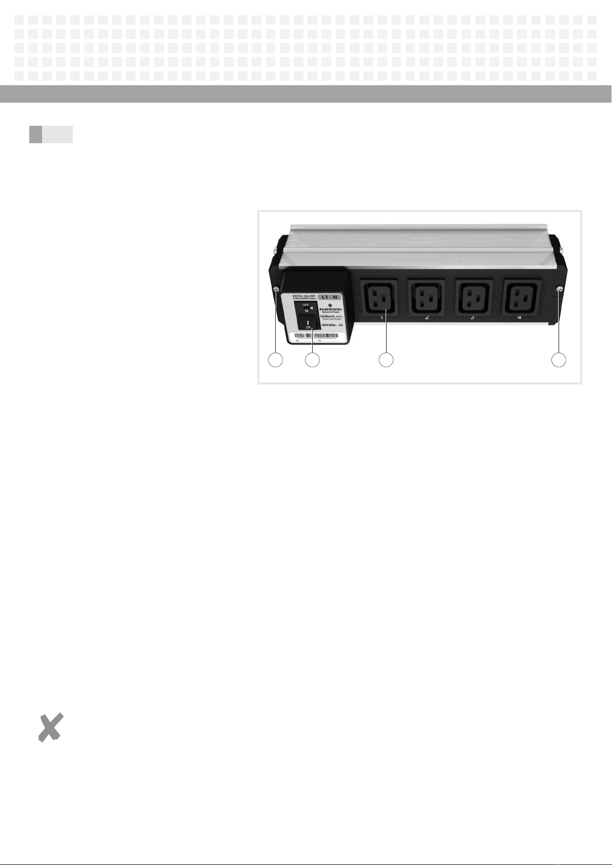
Ausgangsmodul MPX BRM Elementary.–
Alle anderen Systemmodule sind im
User Manual „Liebert®MPX™“ detailliert
beschrieben.
Information
This manual only describes the following:
MPX PEM Elementary power entry–
module and the
MPX BRM Elementary output module.–
All the other system modules are
described in detail in the user manual
entitled “Liebert®MPX™”.
Nota
Le présent manuel décrit uniquement ce
qui suit :
module d’entrée de courant MPX PEM–
Elementary ainsi que le
module de sortie MPX BRM Elementary.–
Tous les autres modules système sont
décrits en détail dans le manuel utilisateur
« Liebert®MPX™ ».
Gefahr!
Die Liebert MPX steht unter ge-
fährlicher Spannung. Befolgen Sie
die folgenden Sicherheitshinweise,
um schwere Verletzungen (unter
Umständen mit Todesfolge) durch
Stromschlag oder Schäden an den an-
geschlossenen Geräten zu vermeiden.
Sobald das Stromeingangsmodul•
an das Stromnetz angeschlossen ist,
stehen die Kontakte an der Unterseite
unter gefährlicher Spannung!
Netzverbindung erst dann herstellen,•
nachdem das Stromeingangsmodul
richtig und sicher auf dem Stromschie-
nengehäuse MPX PRC installiert ist.
Nur ein Stromeingangsmodul pro•
Stromschienengehäuse MPX PRC
anschließen!
Stromeingangsmodul nur durch•
geschultes und für die Ausführung
von Elektroinstallationen qualifiziertes
Personal installieren lassen.
Bei der Installation sicherstellen,•
dass die Module den Leistungs-
anforderungen der angeschlossenen
Komponenten entsprechen.
Das Stromeingangsmodul nie im•
laufenden Betrieb austauschen oder
vom Stromschienengehäuse MPX PRC
nehmen, wenn das Stromnetz noch
angeschlossen ist!
Erst die Stromversorgung unterbre-
chen, dann die integrierten Befestigun-
gen lösen.
Danger
The Liebert MPX handles hazardous
voltage. Follow the safety instruc-
tions to avoid serious injury (in certain
circumstances even death) by electric
shock or damage to the connected
devices.
As soon as the power entry module•
has been connected to the mains, the
contacts on the underside are live with
hazardous voltage.
Do not make the mains connection•
until the power entry module has been
correctly and safely installed on the
MPX PRC power rail chassis.
Only connected on power entry•
module to each MPX PRC power rail
chassis.
Have the power entry module installed•
only be trained personnel who are
qualified to complete electrical instal-
lation work.
During the installation process ensure•
that the modules comply with the
power requirements of the connected
components.
Never replace the power entry module•
whilst it is operating or remove it from
the MPX PRC power rail chassis whilst it
is still connected to the mains.
First disconnect the power supply and
then release the integral fastenings.
Danger !
Le Liebert MPX est sous tension, ce
qui présente des risques. Suivez les
consignes de sécurité ci-dessous afin
d’éviter des blessures graves (pouvant
entraîner la mort) dues à une décharge
électrique ou des dommages aux
appareils raccordés.
Dès que le module d’entrée de courant•
est raccordé au réseau électrique, les
contacts situés sur la face inférieure
sont sous tension et présentent un
danger !
Effectuer le branchement sur le•
secteur seulement après avoir installé
correctement le module d’entrée de
courant sur le châssis de rail d’alimen-
tation MPX PRC et vérifié la sécurité de
l’ensemble.
Raccorder un seul module d’entrée de•
courant par châssis de rail d’alimenta-
tion MPX PRC !
Faire installer le module d’entrée de•
courant uniquement par du personnel
formé et qualifié pour la version des
installations électriques concernée.
Lors de l’installation, s’assurer que les•
modules correspondent à la puissance
exigée pour les composants raccordés.
Ne jamais remplacer le module d’en-•
trée de courant en cours de fonction-
nement, ni le retirer du châssis de rail
d’alimentation MPX PRC quand le
réseau électrique est encore bran-
ché ! D’abord couper l’alimentation
électrique, puis défaire les fixations
intégrées.
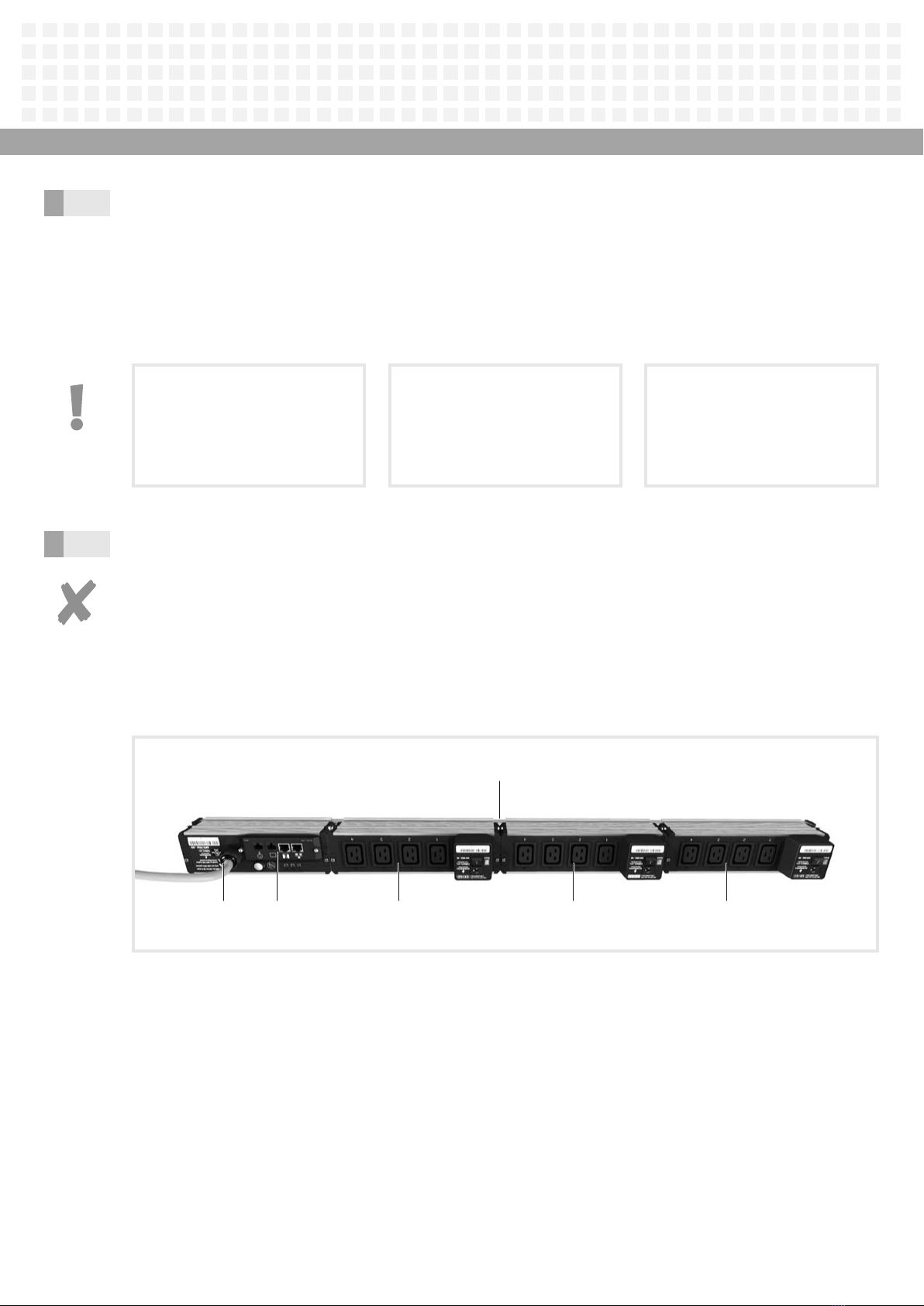
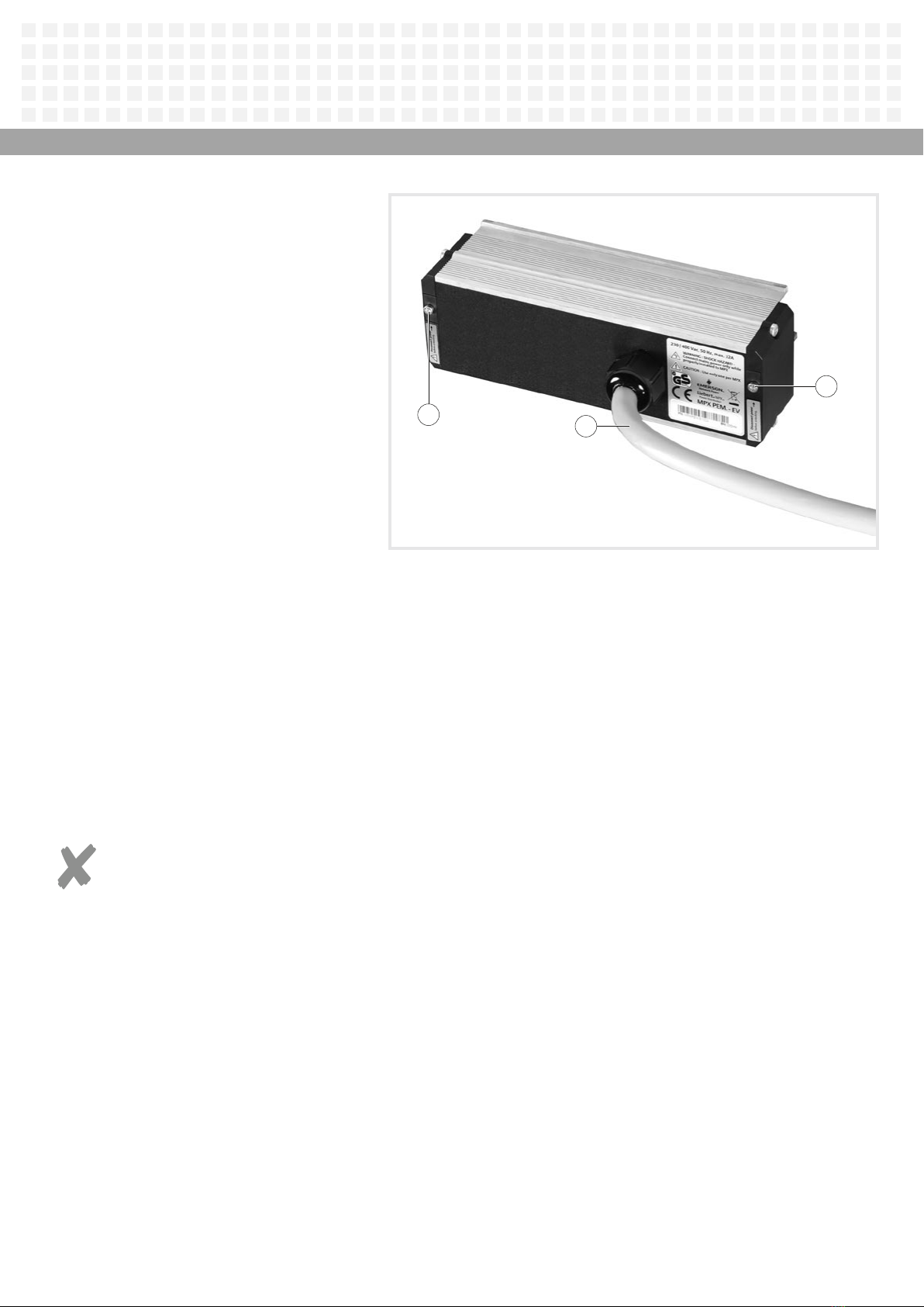
3.1 Stromeingangsmodul
MPX PEM Elementary
Das Stromeingangsmodul MPX PEM ist
die zentrale Stromeinspeisungseinheit
für das Stromschienensystem. Nach der
Befestigung auf dem MPX PRC liefert es
mehrphasigen Strom vom Eingangsnetz an
den Power-Bus des Stromschienengehäuses
und alle angeschlossenen Module.
MPX PEM Elementary
power entry module
The MPX PEM power entry module is the
central power supply unit for the power rail
chassis. After being fastened to the MPX
PRC it supplies multi-phase current from the
input mains to the power bus on the power
rail chassis and all connected modules.
Module d’entrée de courant
MPX PEM Elementary
Le module d’entrée de courant MPX PEM est
l’unité centrale d’alimentation en courant
du système de rail d’alimentation. Après
fixation sur le MPX PRC, il fournit du courant
polyphasé du réseau d’entrée au bus d’ali-
mentation du châssis de rail d’alimentation
et à tous les modules raccordés.
6